$45
CAT DBT - Shield Control Unit PMC-R for Shearer Face Operating Manual - PDF DOWNLOAD
CAT DBT - Shield Control Unit PMC-R for Shearer Face Operating Manual - PDF DOWNLOAD
FILE DETAILS:
CAT DBT - Shield Control Unit PMC-R for Shearer Face Operating Manual - PDF DOWNLOAD
Language :English
Pages :100
Downloadable : Yes
File Type : PDF
IMAGES PREVIEW OF THE MANUAL:
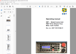
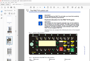
TABLE OF CONTENTS:
CAT DBT - Shield Control Unit PMC-R for Shearer Face Operating Manual - PDF DOWNLOAD
Doc. no.: 4007 139 010 BA 01
Contents
1 About this manual
Before starting work 1 3
Characters and symbols used 1 4
2 Your safety
Further operating manuals 2 3
Personnel 2 3
Installation and repair 2 3
Operating conditions 2 4
Intended use 2 4
Unauthorised use 2 4
Surrounding area conditions 2 4
Prerequisites for operation 2 4
Safety instructions 2 5
General information 2 5
Storage and transport 2 6
Installation and start-up 2 6
Maintenance and repair 2 6
3 Storage and transport
Storage 3 3
Storage of the equipment 3 3
Transport 3 4
Before transport 3 4
Transport containers, dimensions and weights 3 4
4 Assembly
Face shield 4 4
Face end shield 4 5
System drawings 4 7
System drawing Sheet 2 4 8
Data transmission 4 9
5 Operation
The PMC®-R - control unit 5 3
Maintenance of the computers 5 3
Tightening the mounting bolts 5 3
Keyboard allocation for the PMC®-R Program 5 4
Display 5 6
Idle display 5 6
DBT GmbH, Lünen 2005E
Contents
DBT - Shield control system PMC®-R
Emergency OFF 5 6
Display of non-connected or defective sensors 5 7
Menu structure in PMC®-R (columns from left to right) 5 7
Loading program 5 9
Loading a single PMC®-R 5 9
Beginning loading 5 9
Loading from the underground central control 5 12
Setting up a network with PMC®-R 5 14
Troubleshooting 5 17
1 Selected shield function is not performed 5 18
Example 1 5 20
2 Incomplete network 5 21
3 One or several PMC®-Rs are without voltage 5 23
4 One PMC®-R control unit is defective
(no replacement in the longwall) 5 25
5 Brief shutdown of one current group
following activation of a shield function 5 26
6 The display of all PMC®-Rs flashes to indicate an
incomplete network 5 26
7 Data connection (DÜSE) between central control
underground and central control aboveground 5 28
6 Technical data
The PMC®-R control unit 6 3
Design suitable for mining 6 4
Emergency stop/shield support blocked switch 6 4
Rear view of the PMC®-R 6 5
Plug connections longwall PMC®-R 6 5
Brass attachment strip 6 5
Coding plug 6 7
Coding plug SKK24 6 7
Valve connection strip (VA) 6 8
Allocations of connections valve strip 6 8
Allocation of its own shield 6 8
VALVE STRIP CABLE 6 10
Electric power supply 6 12
Isolations adapter (IA) 6 13
Sensors 6 14
Pressure sensor 6 14
Sensors 6 16
Reed measurement rod 6 16
SKK 24 Hose cable system 6 17
Hose cable between valve strip and PMC®-R 6 18
DBT GmbH, Lünen 2005E
Contents
Doc no : 4007 139 010 BA 00 VSVR / 01
VALVE CABLE 6 19
Infrared transmitter 6 21
LD coupler 6 22
Infrared receiver 6 23
SUPPLY ADAPTER PMC/V1; ATEX 6 24
TTY-COUPLER SELF-SUPPLIED; ATEX 6 25
DOUBLE ADAPTER SKK24 BUSH/BUSH 6 26
Loading cable 6 27
Data transmission 6 29
LWL media converter aboveground 6 29
Universal holding plate 6 30
Startup package 6 31
PMC®-P XP Opto Ethernet Provider 6 32
Patch cable 6 35
LWL (fiber-optic cable) device box 6 35
7 For your information
Our service 7 3
Service addresses 7 3
DBT GmbH
S.M 1/4/2025
More products