$41
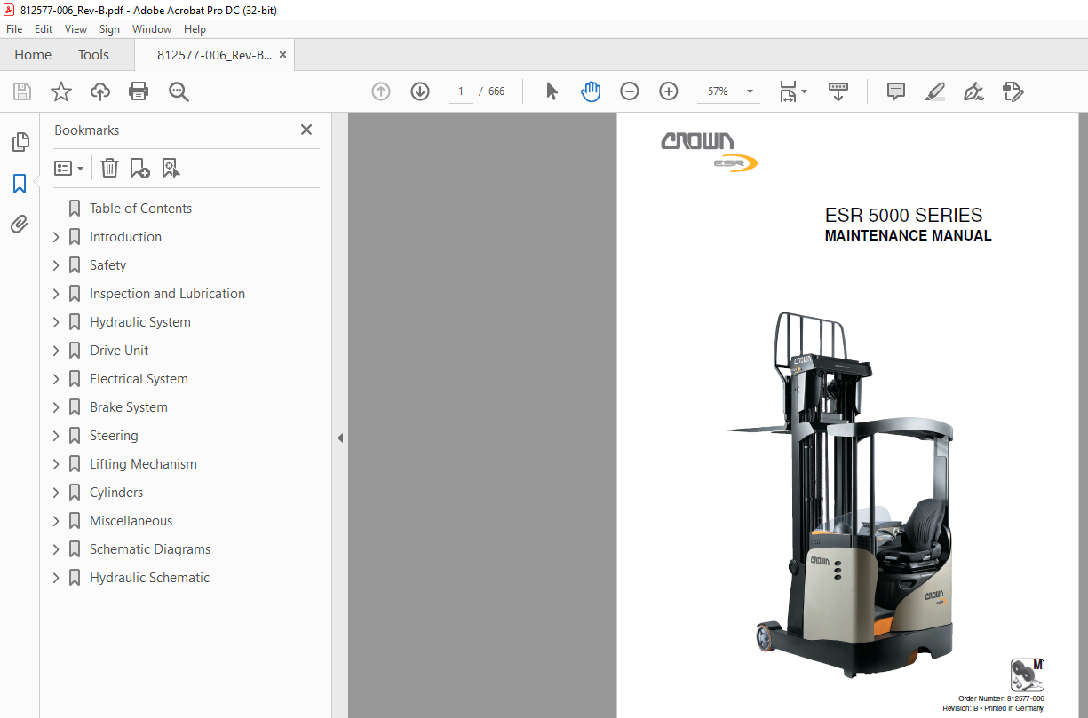
Crown Forklift ESR 5000 SERIES MAINTENANCE MANUAL – PDF DOWNLOAD
Crown Forklift ESR 5000 SERIES MAINTENANCE MANUAL – PDF DOWNLOAD
FILE DETAILS:
Crown Forklift ESR 5000 SERIES MAINTENANCE MANUAL – PDF DOWNLOAD
Language : English
Pages :666
Downloadable : Yes
File Type : PDF
TABLE OF CONTENTS:
Crown Forklift ESR 5000 SERIES MAINTENANCE MANUAL – PDF DOWNLOAD
TABLE OF CONTENTS
INTRODUCTION 1
Important Information 3
Service personnel qualification 3
Ordering Spare Parts 3
Ordering documentation 3
Manual structure 3
Conventions 3
Text mark-ups in the manual 3
Brief description of equipment 3
Truck Data Number 4
SAFETY 5
Safety Notices 7
Basic Safety Notices 8
Organisational measures 8
Truck modifications and additions 8
Personal safety equipment 8
Protecting the hazardous area 8
Hazards from stored energy 8
Maintenance work 9
Restoring the truck to service after maintenance work 9
Cleaning work 9
Handling batteries 9
Warning and instruction decals on the truck 9
Lifting gear and slings 9
Environmental protection 10
INSPECTION AND LUBRICATION 11
Cleaning the Truck and Components 13
Effects of incorrect cleaning 13
Electrical components 13
Roller and slide bearings 13
Corrosion-protected surfaces 13
Environmental protection 13
Cleaning the entire truck 13
Cleaning removed components 14
Cleaning other mechanical components 14
Transport and Storage 15
Safety notices 15
Lifting a non-cold store cab truck with a crane 15
Lifting a cold store cab truck by crane 15
Lifting the truck with a forklift truck 16
Towing the truck 16
Jacking up the truck 17
Truck Assembly and Commissioning 19
Truck assembly 19
Required tools 19
Erecting the chassis 19
Removing the transport retainers 20
Filling the drive transmission unit 22
II
ESR 5000 Series
TABLE OF CONTENTS
Erecting the mast and attaching it to the chassis 22
Placing the Truck in Storage 23
Testing trucks in storage 23
Restoring the truck to service 23
Battery maintenance 23
Component access 24
Accessing components under the panels 24
Components under the panels 25
Accessing the motor compartment 26
Motor compartment 27
Accessing components under the floorboard 28
Components below the floorboard 29
Recommended Lubricants and Consumables 30
Cold store truck requirements 30
Abbreviations used in the table 30
Planned Maintenance 32
Maintenance schedule 32
Annual inspection in accordance with FEM 4004 32
Terms and abbreviations used 32
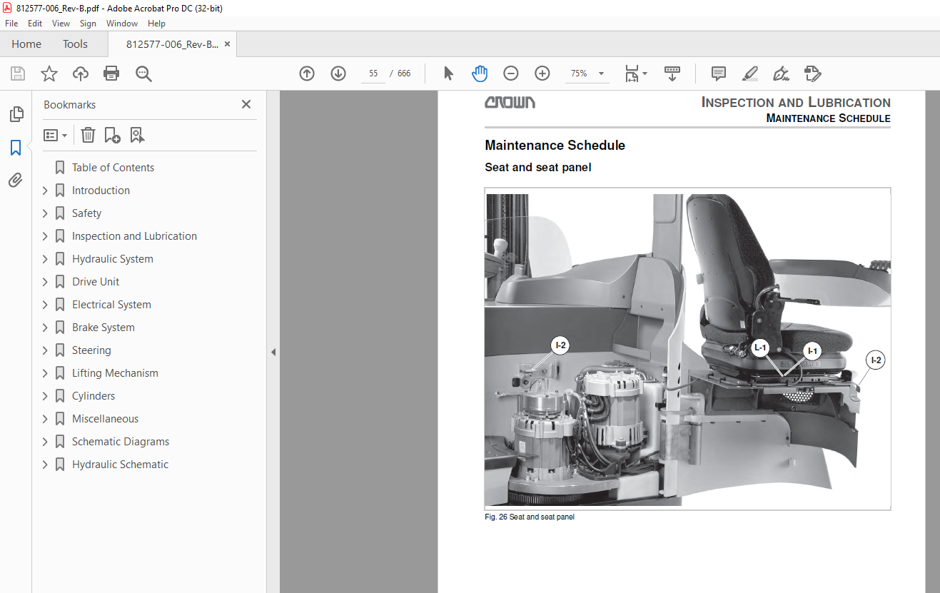
Maintenance Schedule 33
Seat and seat panel 33
Brake system and load wheels 35
Drive unit 37
Reach carriage 39
Hydraulic system 41
Electrical system – part 1 43
Electrical system – part 2 45
Traction and pump motors 47
Mast 49
Fork carriage 51
Torques 53
Standard torques 53
Load Wheels 54
Load wheel replacement 54
Special tools required 54
Load wheel removal 54
Load wheel assembly 55
Support Blocks 56
Checking the support block distance 56
Requirements 56
Measurement 56
Adjusting the support block height 56
Before adjusting 56
Replacing the support blocks 57
Live Ring Bearing Lubrication 58
Replacing the Heater Filter Element 59
HYDRAULIC SYSTEM 61
Abbreviations Used 63
Operation 65
Lifting 65
Lowering 67
Extending the mast reach carriage 69
Retracting the mast reach carriage 70
III
ESR 5000 Series
TABLE OF CONTENTS
Fork tilt back 71
Fork tilt down 72
Sideshift right 73
Sideshift left 74
Hydraulic Components 75
Hydraulic lines 75
Manifolds 75
Main manifold 75
“Accessories” manifold 76
Checking and adjusting relief valve RV1 76
Checking the emergency lowering valve MVL 77
Depressurising the Hydraulic System 78
Bleeding and Flushing the System 79
Safety notices 79
Bleeding the free lift cylinder 79
Bleeding the lift cylinders 79
Bleeding the reach cylinder 79
Bleeding the sideshift cylinder 79
Bleeding the tilt cylinder 79
Bleeding the 5th function cylinder 79
Flushing the lift cylinders 79
Drift tests 80
Requirements 80
Drift Tests 81
Safety notices 81
Lift cylinder drift test 81
Tilt cylinder drift test 81
Hydraulic oil reservoir 82
ESR 5000S hydraulic oil reservoir 82
ESR 5000 hydraulic oil reservoir 82
Replacing the Hydraulic Oil 83
Replacing the Filter 84
Replacing the return filter 84
Replacing the suction filter 84
Replacing the breather filter 85
Replacing the Hydraulic Pump 86
DRIVE UNIT 91
Gear Unit 93
Required tools 93
Removing the gear unit 93
Repairing the gear unit 95
Dismantling the gear unit 95
Assembling the gear unit 95
Assembling the gear unit 97
Drive Wheel 98
Drive wheel disassembly / assembly 98
Drive wheel disassembly 98
Drive wheel assembly 98
ELECTRICAL SYSTEM 99
Electrical Components 101
Service Menu Structure (Software V10) 106
Software version 106
Menu structure 106
Overview of menu items 106
Analyzer 106
A1Status 106
Calibration 107
C1 Acceleration Pedal 107
C2 Raiser/Lower Handle 107
107
C3 Reach Handle 107
C4 Tilt Handle 107
C5 Sice Shift Handle 107
C6 5th Function Handle 107
C7 Height 108
C8 Weight 108
C9 Fork Positioning 108
C10 Reach Retract Slow Down 108
C11 Save? 108
Features 108
Hour Meter 111
Log Events 111
Performance 111
Utilities 112
Performance level defaults 114
Standard settings 114
Service Menu – General (Software V10) 116
Access to service level 116
Trucks with key switch 116
Trucks without key switch 116
Navigation and entry keys 116
Display structure 116
Access to service menu and selecting a sub-menu 117
Analyzer Menu 118
A1 Status 118
A2 Inputs 119
A3 Outputs 124
C1 Accelerator Pedal 126
C2 Raise / Lower Handle 127
C3 Reach Handle 127
C4 Tilt Handle 128
VI
ESR 5000 Series
TABLE OF CONTENTS
C5 Side Shift 129
C6 5th Function 129
C7 Height 130
C73 Height Encoder 131
C8 Weight 134
C9 Fork Positioning 135
C10 Reach Retract 136
C11 Save ? 137
F1 Truck Size 138
F2 Free Lift Switch 139
F3 Height Encoder 139
F4 Lower Cut Out Switch 140
F5 5th Function 140
F6 Maximum Load 141
F7 Capacity Data Monitor 142
F8 Travel Alarm 143
F9 Beacon 143
F10 User Performance 144
F11 User Code 145
F12 Set Language 146
F13 Change Unit 147
F14 Set Rack Select 147
F15 Height/Weight 148
F16 Timer 148
F17 Error Log 148
F18 Operator Alarm 149
F19 Battery Alarm 150
F20 Fork Positioning 150
F21 Choose Steering 150
F25 Keyless Entry 151
F26 Right Handle 151
F27 Options Display 152
F28 Truck Lockout 152
F29 Direction Switch 153
F30 Save ? 153
H1 Truck Complete 154
H2 Traction Module 154
H3 Hydraulic Mod 155
H4 Key On Time 155
H5 Set Service Time 156
L1 History 157
L2 Totals 158
L3 Erase History 158
P1 Setup P1 159
P2 Setup P2 163
P3 Setup P3 163
P4 BDI Setting 163
P5 Travel > LCS 164
P6 Travel > FLS 164
P7 Travel > Custom 165
P8 Lower > Custom 165
P9 Reach > Custom 166
P10 5th Function Left 166
P11 5th Function Right 167
VII
ESR 5000 Series
TABLE OF CONTENTS
P12 Steer Sensitivity 167
P14 Brake at Ramp 168
P15 Set Default Values 168
P16 Save ? 168
U1 Software Version 169
U2 Hour Set 170
U3 Brake Override 170
U4 Check Fan 1 – 4 171
Service Menu Structure (Software V20) 172
Software version 172
Menu structure 172
Overview of menu items 172
Analyzer 172
A1Status 172
Calibration 173
Features 174
Hour Meter 175
Log Events 176
Performance 177
Utilities 178
Performance level defaults 179
PP4 BDI Setting 179
Service Menu – General (Software V20) 181
Access to service level 181
Trucks with key switch 181
Trucks without key switch 181
Navigation and entry keys 181
Display structure 181
Analyzer Menu (Software V20) 182
Access to service menu and selecting a sub-menu 182
A1 Status 182
A2 Inputs 183
A3 Outputs 189
C1 Accelerator Pedal 191
C2 Raise / Lower Handle 192
C3 Reach Handle 192
C4 Tilt Handle 193
C5 Side Shift 194
C6 Height 195
C63 Height Encoder 196
C64 Custom Height 198
C7 Weight 199
C8 Fork Positioning 200
C9 Reach Retract 201
C10 Save ? 202
F1 Truck Size 203
F2 Free Lift Switch 204
F3 Height Encoder 204
F4 Lower Cut Out Switch 205
F5 5th Function 205
F6 Maximum Load 206
F7 Capacity Data Monitor 207
F8 Travel Alarm 208
F9 Beacon 208
VIII
ESR 5000 Series
TABLE OF CONTENTS
F10 User Performance 209
F11 User Code 210
F12 Set Language 212
F13 Change Unit 213
F14 Set Rack Select 213
F15 Height/Weight 214
F16 Timer 214
F17 Error Log 214
F18 Operator Alarm 215
F19 Battery Alarm 216
F20 Fork Positioning 216
F21 Choose Steering 217
F23 Speed Reduction in Turns 217
F24 Sensitive Steering 218
F25 14 km/h 218
F26 Keyless Entry 219
F27 Operation Control 219
F28 Direction Switch 220
F29 Heated Seat 220
F30 InfoLink 221
F31 Save ? 221
H1 Truck Complete 222
H2 Traction Module 222
H3 Hydraulic Mod 223
H4 Key On Time 223
H5 Set Service Time 224
L1 History 225
L2 Totals 226
L3 Erase History 226
P1 Setup P1 227
P2 Setup P2 231
P3 Setup P3 231
P4 BDI Setting 231
P5 Travel > LCS 232
P6 Travel > FLS 232
P7 Travel > Custom 233
P8 Lower > Custom 233
P9 Reach > Custom 234
P10 5th Function Left 234
P11 5th Function Right 235
P12 Steer Sensitivity 235
P13 Brake at Ramp 236
P14 Set Default Values 236
P15 Save ? 236
U1 Software Version 237
U2 Hour Set 238
U3 Brake Override 238
U4 Check Fan 1 – 4 239
U5 Truck Lockout 239
Event Codes 240
Malfunctions with event code display 240
Log book display 240
Malfunctions without event code display 240
Locating malfunctions 240
IX
ESR 5000 Series
TABLE OF CONTENTS
Event Codes 100 – 186 241
Event Code 100 241
Event Code 101 241
Event Code 102 242
Event Code 110 242
Event Code 111 243
Event Code 112 243
Event Code 120 244
Event Code 121 245
Event Code 123 245
Event Code 124 245
Event Code 130 246
Event Code 131 247
Event Code 160 248
Event Code 180 249
Event Code 181 250
Event Code 182 251
Event Code 183 252
Event Code 184 253
Event Code 186 254
Event Codes 200 – 286 255
Event Code 200 255
Event Code 201 256
Event Code 210 257
Event Code 211 257
Event Code 212 259
Event Code 213 259
Event Code 214 260
Event Code 220 261
Event Code 221 262
Event Code 222 263
Event Code 223 264
Event Code 224 265
Event Code 225 266
Event Code 240 267
Event Code 241 268
Event Code 243 269
Event Code 244 270
Event Code 246 271
Event Code 247 272
Event Code 249 273
Event Code 250 274
Event Code 260 275
Event Code 261 276
Event Code 262 277
Event Code 263 278
Event Code 264 279
Event Code 265 280
Event Code 266 281
Event Code 267 282
Event Code 268 283
Event Code 280 285
Event Code 281 285
Event Code 282 285
X
ESR 5000 Series
TABLE OF CONTENTS
Event Code 283 286
Event Code 284 287
Event Code 285 287
Event Codes 300 – 385 289
Event Code 300 289
Event Code 301 289
Event Code 311 290
Event Code 312 291
Event Code 313 291
Event Code 314 291
Event Code 320 292
Event Code 321 293
Event Code 322 294
Event Code 323 295
Event Code 324 296
Event Code 325 297
Event Code 330 297
Event Code 340 299
Event Code 341 300
Event Code 343 301
Event Code 380 303
Event Code 381 303
Event Code 382 303
Event Code 383 304
Event Code 384 305
Event Codes 430 – 465 306
Event Code 430 306
Event Code 431 306
Event Code 460 308
Event Code 461 308
Event Code 462 309
Event Code 463 310
Event Code 464 312
Event Code 465 313
Event Codes 840 – 886 315
Event Code 840 315
Event Code 841 316
Event Code 880 316
Event Code 881 318
Event Code 883 320
Event Code 884 321
Event Code 885 323
Event Code 886 324
Control Modules and Display Screen 325
Replacing control modules 325
Replace the main control module 325
Replacing the traction control module 325
Replacing the hydraulic control module 326
Replacing the steering control module 326
Replacing the display panel 326
PMT Test 328
General 328
Safety Notices 328
Required tools 328
XI
ESR 5000 Series
TABLE OF CONTENTS
Preparing the control module safety test 329
Traction control module safety test 329
Hydraulic control module safety test 329
Steering control module safety test 330
Replacing the Height Encoder 332
Replacing the HGT(R)S Switch 333
Removing the HGT(R)S switch 333
Assembling the HGT(R)S switch 333
Trucks with fingertip control levers 334
Removing the controls 335
Assembling the controls 335
Trucks with dual axis hydraulic control levers 335
Trucks with multi-task handle 336
Removing the controls 337
Assembling the controls 337
Wiring the Multi-Task Control Handle 338
Wiring the Dual Axis Hydraulic Control Levers 339
Wiring the Fingertip Control Levers 340
Replacing the Mast Cables 341
Transfer Point Definition 341
Mast cable removal 341
Mast cable assembly 342
Attaching the mast cable clamps 343
Attaching clamping shoes for a 6 core mast cable 343
Attaching clamping shoes for a 10 core mast cable 343
Replacing the Camera Cable on the Fork Camera 344
Transfer Point Definition 344
Removing the camera cable 344
Camera cable assembly 345
Fitting the camera cable clamps 346
Replacing the Camera Cable on the Mast Camera 347
Transfer Point Definition 347
Removing the camera cable 347
Camera cable assembly 348
Fitting the camera cable clamps 349
Repairing Contactors 350
Wear test 350
Checking contacts 350
Checking the coils 350
Checking the springs 350
Repairing the Main Contactor 351
Replacing the Danaher Drive Motor 352
Drive motor disassembly 352
Drive motor assembly 352
Connecting the power cables 352
Sensor bearing disassembly 355
Sensor bearing assembly 355
Replacing the Crown Drive Motor 356
Drive motor disassembly 356
Drive motor assembly 356
Connecting the power cables 356
Replacing the Pump Motor 358
Removing the pump motor 358
Pump motor assembly 358
XII
ESR 5000 Series
TABLE OF CONTENTS
Connecting the power cables 359
Sensor bearing disassembly 361
Sensor bearing assembly 361
Battery Information 362
Charging the battery 362
Replacing the battery 362
Inserting the Battery Cable Guide 363
Battery with 420 Ah 366
Battery with 560 Ah 366
Battery with 720 Ah 367
Battery with 560 Ah 368
Battery with 720 Ah 368
Battery with 840 Ah 369
Choosing the Correct Battery Cable Length 370
Choosing cable lengths for a T-shaped battery (example) 370
Replacing the battery cable loom in the truck 372
Hole patterns for the battery connectors on the base plate 373
Battery connector DIN 160 (819801-001) 373
Battery connector DIN 160 (819801-101) 373
Battery connector SBE 160 (819801-002) 374
Battery connector SBE 160 (819801-102) 374
Battery connector SB 350 (819801-003) 374
Battery connector SB 350 (819801-103) 374
Heaters (Cold Store Cabs Only) 375
Door heater 375
Replacing and disassembling the heater 375
Replacing the fan 375
Replacing the heater element 376
Replacing the temperature gauge 376
Overhead console heater 376
Replacing and disassembling the heater 376
Replacing the fan 376
Replacing the heater element 377
Replacing the temperature gauge 377
BRAKE SYSTEM 379
Service and Parking Brake 381
Safety notices 381
Service and Parking Brake Danaher Motor 382
Disassembling the brake 382
Dismantling the brake 382
Fitting the brake 382
Assembling the brake 382
Adjusting the air gap 382
Measuring the coil resistance 383
Parking Brake Crown Motor 384
Disassembling the parking brake 384
Dismantling the brake 384
Fitting the brake 384
Assembling the parking brake 384
Adjusting the air gap 384
Measuring the coil resistance 385
Load Wheel Brake 386
General 386
XIII
ESR 5000 Series
TABLE OF CONTENTS
Checking the brake lining wear 386
Replacing the brake linings 386
Wheel brake cylinder 387
Wheel brake cylinder disassembly 387
Wheel brake cylinder assembly 387
Bleeding the load wheel brake 387
Replacing the brake fluid 387
Testing and Adjusting the Brake Pedal Clearance 388
Adding Brake Fluid 389
Brake Power Control 390
Requirements 390
Required tools 390
Brake test 390
STEERING 393
Function 395
Generating a steering signal 395
Steer motor activation 395
Steer system monitoring 395
Error correction 395
Quadrant – definition 396
Steering Errors 397
Error routine 397
Ending the error routine 397
Causes of error routine activation 397
Other error causes 397
Examples of steer faults 398
Proximity Switches up to Serial No 5A215757 400
Replacing and adjusting SFS2 or SFS1 SA 400
Proximity Switches from Serial No 5A215758 401
Replacing and adjusting SFS2 or SFS1 SA 401
Steer Motor and Steering Transmission 402
Removing the steer motor and steering transmission 402
Disconnecting the steering transmission and steer motor 402
Assembling the steering transmission and steer motor 403
Installing the steer motor and steering transmission 403
Steering Wheel 405
Steering wheel removal 405
Steering wheel assembly 405
Replacing Encoder ECR2 407
Removing ECR4 407
Assembling ECR4 407
LIFTING MECHANISM 409
Mast 411
Safety instructions for working on the mast 411
General 411
Torques 411
Lifting gear minimum capacities 411
Checking the assembled mast 411
Flaking 411
Checking the roller tracks 411
Checking the mast verticality 411
XIV
ESR 5000 Series
TABLE OF CONTENTS
Checking the pulleys, hoses and cables 412
Checking the end stops 412
Checking the fork setting 412
Checking the mast tilt 412
Mast tilt tolerance tables 413
Adjusting the Mast Tilt 414
Mast Removal / Assembly 415
General 415
Mast removal 415
Mast assembly 416
Mast checks and settings after assembly 417
Dismantling and Assembling the Mast 419
Safety notices 419
Tips & tricks 419
Dismantling the mast 419
Fork carriage removal 419
Removing the 2nd mast stage 419
Removing the 1st mast stage 419
Replacing the Mast Rollers 421
General 421
Safety notices 421
Preparation 421
Mast roller assembly 421
Calculating the roller diameter 421
Calculating the number of shims required 424
Final tasks and settings 426
Integrated sideshifter 427
Removing the integrated sideshifter 427
Assembling the integrated sideshifter 427
Lift Cylinder Removal and Assembly 429
Safety notices 429
Lift cylinder removal on masts up to 8 m 429
Lift cylinder assembly on masts up to 8 m 430
Lift cylinder removal on masts above 8 m 432
Lift cylinder assembly on masts above 8 m 432
Reach Cylinder Removal and Assembly 433
Safety notices 433
Removal 433
Assembly 434
Free Lift Cylinder Removal and Assembly 435
Safety notices 435
Removal 435
Installing the free lift cylinder in an upright mast 436
Installing the free lift cylinder in a horizontal mast 436
Chain Supports and Lift Chains 438
General 438
Periodic inspection of chain supports and lift chains 438
Periodic replacement of chain supports and lift chains 438
Cleaning lift chains 438
Inspecting Chain Supports and Lift Chains 439
Checking the service hours for the lift chains and anchor bolts 439
Checking the lift chain for elongation 439
General 439
Preparatory measures 439
XV
ESR 5000 Series
TABLE OF CONTENTS
Freedom of movement 440
Worn or missing plates 440
Turned pins 441
Corrosion 441
Chain lateral wear 441
Checking chain supports and anchor bolts 442
Checking the chain pulleys 442
Checking and adjusting the chain tension 442
Checking and adjusting the tension on the outer chains 442
Checking and setting the free lift chain tension 442
Checking the lifting components for misalignment 443
Lubricating Lift Chains 444
General information 444
Lubrication intervals and lubricants 444
Separating Lift Chains 445
Tools and equipment required 445
Forks 446
General 446
Terms 446
Fork marking 446
Fork Inspection 447
Checking fork tines for cracks 447
Checking fork tip straightness 447
Measuring the fork blade warping 448
Measuring the fork tip width 448
Measuring the fork tine height difference 448
Checking the fork stop 448
Measuring the fork blade wear 449
Reach Carriage, Terms and Definitions 450
Terms 450
“Left outrigger” and “Right outrigger” definition 450
Reach Carriage Removal and Assembly 451
Reach carriage removal 451
Reach carriage assembly 451
Adjusting the Reach Carriage (up to serial no 5A213106) 452
Adjusting the Reach Carriage (from serial no 5A213108) 454
CYLINDERS 457
General 459
Safety notices 459
Hydraulic System Repair Instructions 459
Tools 460
Small hook 460
Extractor 460
Producing extractors 460
Groove aligning arbor for small rod seals 460
Assembly devices for large rod seals 461
Protective mechanisms 461
Rod Seal Removal and Assembly 462
Removing a large rod seal 462
Removing a small rod seal 462
Inserting a large rod seal 462
Fitting a small rod seal 463
Rod seal assembly, sealing lip first 463
XVI
ESR 5000 Series
TABLE OF CONTENTS
Repairing Cylinders 464
Safety notices 464
General 464
Replacing the rod seals 464
Repairing Lift Cylinders 465
Dismantling lift cylinders 465
Lift cylinder assembly 465
Piston rod pre-assembly and installation 465
Piston cap pre-assembly and installation 465
Final tasks 466
Repairing the Free Lift Cylinder 468
Dismantling the free lift cylinder 468
Free lift cylinder assembly 468
Piston rod pre-assembly and installation 468
Piston cap pre-assembly and installation 468
Final tasks 469
Repairing the Reach Cylinder 471
Dismantling the reach cylinder 471
Piston rod pre-assembly and installation 471
Piston cap pre-assembly and installation 471
Final tasks 472
Repairing the Sideshifter Cylinder 474
Dismantling the sideshifter 474
Sideshifter cylinder assembly 474
Final tasks 474
MISCELLANEOUS 477
Replacing the Cold Store Cab Windows 479
Important notes 479
Engineer qualifications 479
Cure times 479
Approved adhesives and primers 479
Cleaning the glued surfaces and windows 479
Ambient conditions for repair work 479
Safety Notices 479
Tools required 479
Removing damaged windows 479
Fitting new windows 480
Gluing the window 480
Final tasks 482
SCHEMATIC DIAGRAMS 485
Wire Colour Code 487
General Contact Symbol Abbreviations 488
Electrical wiring diagrams 490
Power up circuit 492
Wire Harness / Wiring Diagram Assignment 493
Wiring Diagram, Fingertip and Dual Axis Hydraulic Control Levers No 822617 495
Wiring Diagram, Multi-Task Control Joystick 822618 498
Wiring Diagram No 822790 (All Joystick Versions) 501
Main Harness, Part Number 827090 504
Main Harness, Part Number 819849 507
Main Harness, Part Number 825335 509
XVII
ESR 5000 Series
TABLE OF CONTENTS
Replacement Parts 512
Main Harness, Part Number 819850 525
Harness, ESR 5000S Armrest 544
Connector table 545
Wire Harness Distributor Plate to Reach Carriage Part Number 822740 563
Wire Harness Distributor Plate to Reach Carriage Part Number 827091 564
Manifold, mast wire harness 569
Replacement Parts 569
Plug connector housing 571
Contact pins 571
Replacement Parts 571
Plug connector housing 573
Contact pins 573
Replacement Parts 573
Contact pins 574
Replacement Parts 574
Plug connector housing 575
Contact pins 575
Replacement Parts 575
Plug connector housing 576
Contact pins 576
Replacement Parts 576
576
Contact pins 577
Replacement Parts 577
Plug connector housing 578
Contact pins 578
Spare parts 578
Plug connector housing 579
Plug connector housing 580
Contact pins 580
Plug connector housing 581
Contact pins 581
Note on assembly: 582
Plug connector housing 582
Contact pins 582
Plug connector housing 583
Contact pins 583
Plug connector housing 584
Contact pins 584
Plug connector housing 585
Contact pins 585
Plug connector housing 586
Contact pins 586
Plug connector housing 587
Contact pins 587
Note on assembly: 588
Plug connector housing 588
Contact pins 588
Plug connector housing 589
Contact pins 589
Note on assembly: 590
Plug connector housing 590
Contact pins 590
XVIII
ESR 5000 Series
TABLE OF CONTENTS
Plug connector housing 593
Contact pins 593
Plug connector housing 594
Contact pins 594
Plug connector housing 595
Contact pins 595
Beacon Wire Harness, Option 599
Plug connector housing 599
Contact pins 599
24 V Work Lights Wire Harness, Option 600
Plug connector housing 600
Contact pins 600
Cable lugs and rings 600
600
Travel Alarm Wire Harness, Option 601
Plug connector housing 601
Contact pins 601
Plug connector housing 602
Contact pins 602
DC / DC Converter Wire Harness, Option 605
Replacement Parts 605
Plug connector housing 609
Contact pins 609
12 V Work Lights Wire Harness, Option 613
Plug connector housing 613
Contact pins 613
Cable lugs and rings 613
InfoLink, Wire Harness, Option 617
Plug connector housing 617
Contact pins 617
Cable lugs and rings 617
Replacement Parts 621
Plug connector housing 622
Contact pins 622
Replacement Parts 622
Replacement Parts 623
Replacement Parts 624
Cable lugs and rings 625
Replacement Parts 625
Cold Store Cab Main Harness 629
Door wire harness (cold store cab) 630
Sheet 1 (Cold Store Cab) 631
Sheet 2 (Cold Store Cab) 632
Sheet 3 (Cold Store Cab) 633
Sheet 4 (Cold Store Cab) 634
Sheet 5 (Cold Store Cab) 635
HYDRAULIC SCHEMATIC 637
Hydraulic Symbols 639
Hydraulic Diagram 643
1
INTRODUCTION
IMAGES PREVIEW OF THE MANUAL:

More products