$37
Crown Forklift FC 5200 Series Counter Balanced Service Manual – PDF DOWNLOAD
Crown Forklift FC 5200 Series Counter Balanced Service Manual – PDF DOWNLOAD
FILE DETAILS:
Crown Forklift FC 5200 Series Counter Balanced Service Manual – PDF DOWNLOAD
Language : English
Pages :339
Downloadable : Yes
File Type : PDF
TABLE OF CONTENTS:
Crown Forklift FC 5200 Series Counter Balanced Service Manual – PDF DOWNLOAD
Componentry 1
Introduction 1
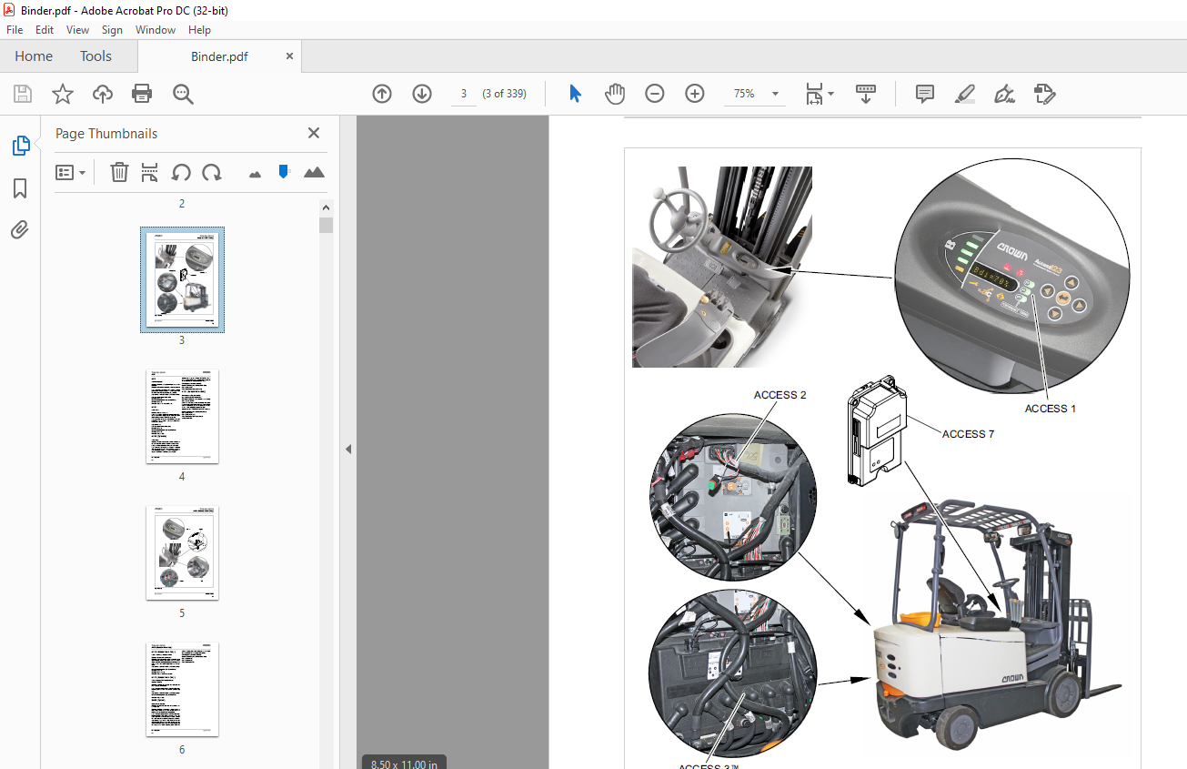
Access 1 2
Access 2 2
Access 3™ 2
Access 7 (EPV Only) 2
ACS 4
ALM1 4
ALM2 (Optional) 4
AXS1 (Manual Valve Only) 4
AXS2 (Manual Valve Only) 6
BRES (Option) 6
BRKS2 (Option) 8
CR7 (Not Shown) 12
CR38 (Not Shown) 12
DR1 12
DR2 14
DR3 14
DS20 14
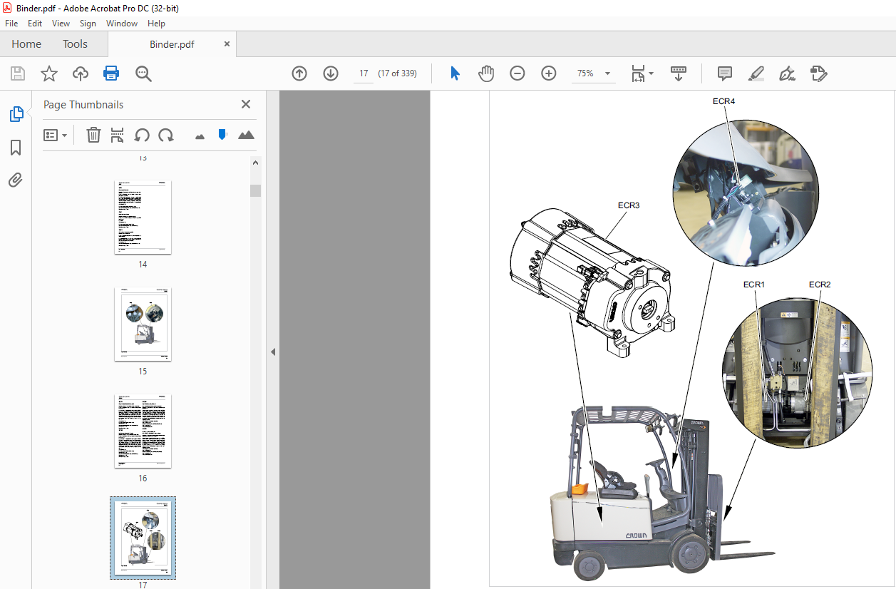
ECR1 16
ECR2 16
ECR3 16
ECR4 16
FAN1 18
FAN2 18
FAN4 18
FAN5 18
FAN6 18
FLS (Not Shown) 20
FNS 20
FS 20
FU1 20
FU2 20
FU4 22
FU6 22
FU7 22
FU8 (Not Shown) 22
HGTS1 24
HGTS2 24
HGTS3 24
HN1 26
HNS1 26
HNS2 26
HNS3 26
HNS4 (EPV Only) 26
HNS5 26
HR1 (Optional – Not Shown) 28
HR2 (Optional – Not Shown) 28
Impact Sensor 28
InfoLink® (Optional) 28
K1 30
K2 30
K5 30
KYS 30
L 32
LGS1 (Optional) 32
LGS2 (Optional) 32
LGT1 (Optional) 32
LGT2 (Optional) 32
LGT3 (Optional) 34
LGT4 (Optional) 34
LGT5 (Optional) 34
LGT6 (Optional) 34
M1 36
M2 36
M3 36
ORS (EPV Only) 38
ORS1 (Manual Valve Only – Not Shown) 38
ORS2 (Manual Valve Only – Not Shown) 38
ORS3 (Manual Valve Only – Not Shown) 38
POT1 40
POT2 40
POT3 40
POT4 40
POT5 (EPV Only) 42
POT6 (EPV Only) 42
POT7 (EPV Only) 42
POT8 42
PT1 44
RES1 (Optional) 44
RES2 (Optional) 44
RES3 (Optional) 44
RES4 (Optional – Not Shown) 44
RES39 (Optional – Not Shown) 44
RES5 (Optional – Not Shown) 46
RES6 (Optional – 48 V Trucks Only – Not Shown) 46
RES7 (Optional – 48 V Trucks Only – Not Shown) 46
RES50 (Optional – Not Shown) 46
RS 46
SB80 (Optional – Not Shown) 46
SBS (Optional) 48
SES 48
SPA1A (EPV Only) 48
SPA1B (EPV Only) 48
SPA2A (EPV Only) 50
Parts Breakdown: 024-2052-150 (1) 024-2052-200 (1) 50
SPA2B (EPV Only) 50
SPL (EPV Only) 50
SPR (EPV Only) 50
SPTE (EPV Only)153
SPTR (EPV Only) 52
SV1 (Manual Valve Only) 52
SV3 (Manual Valve Only) 52
SVBy (EPV Only) 54
SVC1 (EPV Only – Not Shown) 54
SVL (EPV Only – Not Shown) 54
SVOP (Manual Valve Only) 54
SVX (Manual Valve Only, Optional – Not Shown) 56
TBS (Manual Valve Only) 56
THS1 (Optional) 56
THS2 (Optional) 56
TLMS 56
TLT (Manual Valve Only) 58
TPAS (Optional) 58
TR1160
TR2 58
Parts Breakdown: N/A 58
TS1 58
TS2 58
TS3 60
TSS (Option) 60
VTS 60
Hydraulic System 63
Hydraulic Lines and Fittings 63
Avoid High Pressure Fluids-Escaping fluid under pressure can penetrate the skin causing serious injury Relieve pressure before disconnecting hydraulic lines Tighten all connections before applying pressure Keep hands and body away from pin-holes w 63
Reservoir 63
Capacity 63
Fig 1 (30576) 64
Fig 2 (17440) 64
Filters 64
Fig 3 (30567) 64
Drift Test 65
Never stand or work under a suspended load 65
Tilt Drift Test 65
Lift Drift Test 65
Cylinder and Circuit Bleeding 65
Do not attempt to bleed a line by cracking an O-ring face seal fitting This will result in damaging the O-ring which then must be replaced to prevent hydraulic fluid leakage 65
Lift Circuit 66
Fig 4 (30568) 66
Tilt Circuit 67
Fig 5 (30569) 67
Tilt Cylinder Bleeding 67
Do not attempt to bleed a line by cracking an O-ring face seal fitting This will result in damaging the O-ring which then must be replaced to prevent hydraulic fluid leakage 67
Sideshift Circuit 67
Steer Cylinder Circuit 67
Hydraulic Circuitry 68
Manual Steering 68
Fig 1 (30578) 68
No Demand for Steering 68
Fig 2 (30397) 69
Steer Left 70
Fig 3 (30398) 71
Steer Right 72
Fig 4 (30399) 73
Lift 74
Fig 5 (30400) 75
Lower Circuit 76
Fig 6 (30401) 77
Tilt Back Circuit 78
Tilt Position Assist 78
Fig 7 (30402) 79
Tilt Forward Circuit 80
Tilt Position Assist 80
Fig 8 (30403) 81
Sideshift Left Circuit 82
Fig 9 (30404) 83
Sideshift Right Circuit 84
Fig 10 (30405) 85
Notes: 86
Lift Pump 87
Disassembly 88
Assembly 88
Control Valve 89
Relief valve RV1 operation 89
Relief valve RV2 operation 89
Main pressure compensating element (MPCE) operation 91
Control valve disassembly 92
Inspecting and repairing the control valve 93
AXS1, AXS2, TLT107
TBS108
ACS109
BRKS1, BRKS2 (Optional)110
HGTS1110
TLMS112
Access 1 2 3® Menus113
Analyzer Menus151
Features Menus168
Performance Menus181
Calibration Menus202
Hours Menus209
Events Menus212
Utilities Menus214
Contactors219
132084-003/-004 Contactor L (Line) and P (Pump)219
Before any inspection, adjustments, servicing, parts replacement or any other act is performed requiring physical contact with the electrical working components or wiring of these contactors, disconnect battery, raise drive wheels clear of floor and 219
Inspection219
Contacts219
Line and Pump Contactor220
Coil220
Component Replacement220
Fig 1 (17400)220
Contact Replacement221
Coil Replacement221
“EE” Component Replacement221
Fig 2 (17401)221
Contact Replacement222
Coil Replacement222
Battery223
Safety Rules223
Checking the Battery223
Battery Care224
Charging the Battery224
Battery Removal225
Battery Installation226
Seat Deck Cover Adjustment227
Seat Deck Latch Adjustment227
Seat Deck Cylinders228
Battery Cleaning230
Troubleshooting230
Dual Voltage Conversion230
Battery Discharge Interrupt Performance (P4)230
Brake291
Checking Brake Wear291
Brake Disassembly292
Brake Assembly294
Steering Column297
Hydrostatic Steering Unit297
Fig 1 (30566)297
The steering on your lift truck can be reversed by incorrectly connecting the hydraulic hoses Care should be exercised when maintenance is performed on the steering system Prior to disassembly, mark hose and tube locations so they can be properly a297
Steering Column Assembly298
Fig 2 (15149-01)298
Column298
Fig 3 (20083)298
Fig 4 (15154-01)299
Gas Cylinder299
Fig 5 (20084)299
Fig 6 (20085)299
Directional Control299
Fig 7 (15157-01)299
Fig 8 (15158-01)300
Steering Wheel Removal300
Fig 9 (15159-01)300
Fig 10 (15160-01)300
Fig 11 (15161-01)301
Steering Wheel301
Fig 12 (20104)301
Final Assembly301
Steer Axle302
Mast306
Wear appropriate protective items such as eye protection, work gloves, and safety-toe shoes whenever performing maintenance work on Crown equipment306
Pivot Block Torque Requirements306
Fig 1 (25469)306
Mast Flaking306
Mast Testing (Assembled)307
Fig 2 (16947)307
Shim Basics307
Fig 3 (17406-02)307
Fig 4 (16950-01)308
Shim Removal309
Wear appropriate items, such as eye protection and safety-toe shoes whenever performing maintenance work Do not place fingers, hands or arms through mast or position them at pinch points In this section you may be required to lift and block the lif309
Mast Column Rollers309
Fig 5 (17407)309
Carriage Column Roller Adjustments310
Fig 6 (17408-01)310
Fig 7 (17409-01)310
Fig 8 (17410-01)310
Wear appropriate items, such as eye protection and safety-toe shoes whenever performing maintenance work Do not place fingers, hands, or arms through mast or position them at pinch points In this section you may be required to lift and block the li311
Carriage Side Thrust Roller Adjustments (TL, TF, and TT Masts)311
Fig 9 (17411-01)311
Fig 10 (17412-01)311
Mast Column Roller Removal – TT and TF Mast (Inner Mast)312
Mast Column Rollers Removal – TL and TF Mast313
Mast Assembly313
Lift Cylinder Removal – TL, TF, and TT313
Carriage Removal – TT and TF Mast314
Wear appropriate items, such as eye protection and safety-toe shoes whenever performing maintenance work Do not place fingers, hands, or arms through mast or position them at pinch points In this section you may be required to lift and block the li314
Carriage Removal – TL Mast314
Wear appropriate items, such as eye protection and safety-toe shoes whenever performing maintenance work Do not place fingers, hands, or arms through mast or position them at pinch points In this section you may be required to lift and block the li314
Mast Removal (TL and TT Mast)315
Wear appropriate items, such as eye protection and safety-toe shoes whenever performing maintenance work Do not place fingers, hands, or arms through mast or position them at pinch points In this section you may be required to lift and block the li315
Fig 11 (17413)315
Make sure lifting device and sling are sufficiently rated to withstand the weight being lifted Never work under or around a lift truck that is not properly secured See lift truck data plate for lift truck weight information315
Fig 12 (17414-01)316
Fig 13 (17415-01)316
Mast Assembly (TL and TT Mast)317
Fig 14 (25469)317
All hydraulic lines, hoses have an o-ring face seal to prevent hydraulic fluid leakage These o-ring face seals must be replaced to prevent hydraulic fluid leakage whenever the lines are disconnected317
Fig 15 (17416-02)318
Fig 16 (20922)318
TT Mast319
TL Mast319
Fig 17 (17417-02)319
Tilt Cylinder Adjustments320
Wear appropriate items, such as eye protection and safety-toe shoes whenever performing maintenance work Do not place fingers, hands, or arms through mast or position them at pinch points In this section you may be required to lift and block the li320
Quad Mast320
Mast Flaking320
Mast Testing (Assembled)321
Fig 18 (16947)321
Wear appropriate items, such as eye protection and safety-toe shoes whenever performing maintenance work Do not place fingers, hands, or arms through mast or position them at pinch points In this section you may be required to lift and block the li321
Mast Removal322
Wear appropriate items, such as eye protection and safety-toe shoes whenever performing maintenance work Do not place fingers, hands, or arms through mast or position them at pinch points In this section you may be required to lift and block the li322
Carriage Removal322
Carriage Inspection322
Lift Chain Tension322
Fig 19 (17419-01)323
Fig 20 (17420-01)324
Notes:325
Tilt Cylinder326
Bleeding the cylinder and the circuit329
Tilt drift test329
Tilt cylinder adjustments329
IMAGES PREVIEW OF THE MANUAL:
More products