$41
Crown Forklift GPC 3000 Series Service Manual – PDF DOWNLOAD
Crown Forklift GPC 3000 Series Service Manual – PDF DOWNLOAD
FILE DETAILS:
Crown Forklift GPC 3000 Series Service Manual – PDF DOWNLOAD
Language : English
Pages :680
Downloadable : Yes
File Type : PDF
GPC 3020
GPC 3040
GPC 3045
GPC 3050
GPC 3055
GPC 3060
TABLE OF CONTENTS:
Crown Forklift GPC 3000 Series Service Manual – PDF DOWNLOAD
Introduction 0
Safety 0
Organisation of the Safety Messages 2
Basic Safety Messages 3
Organisational measures 3
Modifications to the forklift truck 3
Personal protection equipment 3
Securing hazardous areas 3
Hazards posed by stored energy 3
Maintenance work 4
Restoring the forklift truck to service after maintenance work 4
Cleaning work 4
Handling batteries 4
Warning and instruction decals on the forklift truck 4
Lifting equipment and lifting accessories 5
Environmental protection 5
Inspection and Lubrication 0
Storing and Returning the Forklift Truck to Service 2
Cleaning the Forklift Truck and Componentry 3
Effects of incorrect cleaning 3
Electrical components 3
Roller and slide bearings 3
Corrosion-protected surfaces 3
Environmental protection 3
Cleaning the entire forklift truck 4
Cleaning removed componentry 5
Cleaning other mechanical componentry 5
Jacking up the Forklift Truck 6
Lifting the Forklift Truck by Crane 8
Towing the Forklift Truck 10
Securing the Forklift Truck on a Loading Surface 11
Securing GPC 3020, 3040, 3060 11
Securing GPC 3045 und 3055 12
Planned Maintenance 13
Maintenance schedule 13
Annual inspection in accordance with FEM 4004 13
Used terms and abbreviations 13
Maintenance Schedule 14
General 14
Covers 15
Hydraulic system 16
Power unit 17
Electrical system 18
Braking system 19
Steering 19
Lifting mechanism 20
Cylinders 21
Platform 21
Miscellaneous 22
GPC 3020/40/50/60 Inspection and Lubrication Points 23
GPC 3045 Inspection and Lubrication Points 25
GPC 3055 Inspection and Lubrication Points 27
Lubricants and Auxiliary Materials 29
Cold store truck requirements 29
Abbreviations used 29
Componentry 0
Componentry 2
Audible Indicators 3
HORN 3
ALM 3
Encoders 4
ECR1 4
ECR2 4
ECR3 4
Valves 5
CV 5
PV 5
RV1 6
RV2 6
SV 6
SV1 6
SV2 7
Motors 8
M1 8
M2 8
M3 8
Potentiometers 9
POT 9
Relay 10
K1 10
Switch 11
BLS 11
BLS2 11
BLS3 11
BRS 11
FS (PF) 11
HNS1 12
HNS2 12
HSS 12
KYS 12
LMS5 13
LMS6 13
LMS7 13
LMS71 14
LMS8 14
LMS9 14
LMS10 14
LOS1 14
LOS2 15
LOS3 15
LOS4 15
LOS5 15
LOS6 15
LOS7 15
PPCS1 16
PPCS2 16
RAS 16
RAS2 16
RAS3 16
RAS4 17
RAS5 17
SAS 17
Contactors 18
LINE 18
Sensors 19
FPS1 19
FPS2 19
LS 19
SAHS 19
TS1 20
TS2 20
STEER SENSOR 20
Fuses 21
FU1 21
FU2 21
FU3 21
FU7 21
FU8 22
Control Modules 23
Access 1 23
Access 2/3 23
Access 5 23
Access 81 23
Access 82 24
Miscellaneous 25
BRK 25
DC-DC CONVERTER 25
FAN 25
Keypad 25
PWS 26
RT PCB 26
TFD UNIT 26
Hydraulic Cylinder 27
Lift cylinder 27
Platform cylinder 27
Up to S/N 5A416979: Overview 28
Starting with S/N 5A416980: Overview 29
Electrical Components 30
Hydraulic System 0
Safety and Maintenance Instructions 2
Hydraulic lines and ports 2
Bleeding the hydraulic system 2
Drift test 2
Changing the Hydraulic Oil 3
Overview of Pressure Relief Valves 4
12-kW unit, hydraulic unit with single function (up to S/No 5A409929) 4
13-kW unit, hydraulic unit with single function (from S/No 5A409930) 4
22-kW hydraulic unit with single function 4
22-kW hydraulic unit with dual function 4
Replacing the Pressure Relief Valve 5
Testing and Adjusting the Pressure-Relief Valves 6
RV1 test 6
RV2 test 6
Adjusting RV1 or RV2 6
Removing and Installing the Hydraulic Unit 7
Removing the hydraulic unit 7
Installing the hydraulic unit 7
Repairing the 12-kW Hydraulic Unit (Up to S/No 5A409929) 8
Starting up the hydraulic unit 8
Repairing the 13-kW Hydraulic Unit (From S/No 5A409930) 10
Starting up the hydraulic unit 11
Repairing the 22-kW Hydraulic Unit 12
Starting up the hydraulic unit 12
Drive Unit 0
Changing the Transmission Oil 2
Change interval 2
Permissible oil types 2
Special features 2
Preparing to change the oil 2
Draining the oil 2
Adding the oil 2
Power Unit Componentry 3
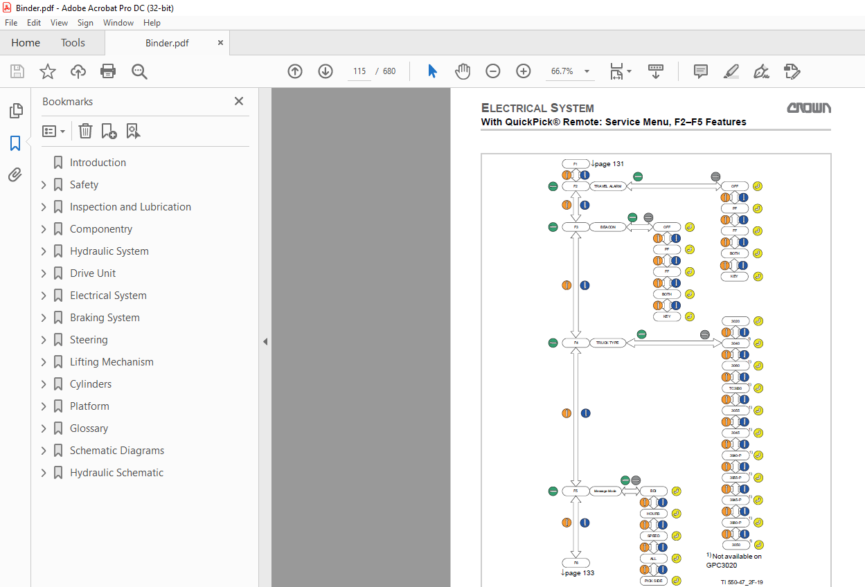
Electrical System 0
Control Modules and Power Fuses 2
General 2
Power fuses 2
Servicing and Replacing the Control Modules 3
Discharging the capacitors 3
Servicing the control modules 3
Replacing the control module 3
Selecting Service Levels 5
Select service preset 2 5
Select service preset 3 5
With QuickPick® Remote: Determining the Software Version 6
Retrieving the forklift truck code 6
Retrieve individual modules 6
Without QuickPick® Remote: Menu Structure – Overview 7
With QuickPick® Remote: Pairing Submenu 8
With QuickPick® Remote: Operator Menu 9
With QuickPick® Remote: Operator Menu 10
With QuickPick® Remote: Service Menu, Analyzer A1 11
With QuickPick® Remote: Service Menu, Analyzer A2 12
With QuickPick® Remote: Service Menu, Analyzer A3 13
With QuickPick® Remote: Service Menu, Analyzer A3 14
With QuickPick® Remote: Service Menu, Analyzer A2 Inputs 15
With QuickPick® Remote: Service Menu, Analyzer A3 Inputs 16
With QuickPick® Remote: Service Menu, Analyzer A5 Inputs 17
With QuickPick® Remote: Service Menu, Analyzer A6 Inputs 18
With QuickPick® Remote: Service Menu, Analyzer A8 Inputs 19
With QuickPick® Remote: Service Menu, Analyzer A8 Inputs 20
With QuickPick® Remote: Service Menu, Analyzer A8 Output 21
With QuickPick® Remote: Service Menu, C1 and C3 Calibration 22
With QuickPick® Remote: Service Menu, C2 Calibration 23
With QuickPick® Remote: Service Menu, F1 Features 24
With QuickPick® Remote: Service Menu, F2–F5 Features 25
With QuickPick® Remote: Service Menu, F6–F12 Features 26
With QuickPick® Remote: Service Menu, F73–F74 Features 27
With QuickPick® Remote: Service Menu, F13–F20 Features 28
With QuickPick® Remote: Service Menu, F21 Features 29
With QuickPick® Remote: Service Menu, F22–F26 Features 30
With QuickPick® Remote: Service Menu, Hours 31
With QuickPick® Remote: Service Menu, Events 32
With QuickPick® Remote: Service Menu, P1 Performance 33
With QuickPick® Remote: Service Menu, P2 Performance 34
With QuickPick® Remote: Service Menu, P3 Performance 35
With QuickPick® Remote: Service Menu, P4–P16 Performance 36
With QuickPick® Remote: Service Menu, P16–P99 Performance 37
With QuickPick® Remote: Service Menu, U1 Utilities 38
With QuickPick® Remote: Service Menu, U1–U2 Utilities 39
With QuickPick® Remote: Service Menu, U1–U2 Utilities 40
Without QuickPick® Remote: Determining the Software Version 41
Without QuickPick® Remote: Menu Structure – Overview 42
Without QuickPick® Remote: Operator Menu 43
Without QuickPick® Remote: Analyzer Menu A1 Status 45
Without QuickPick® Remote: Analyzer Menu Access 3 Outputs 46
Without QuickPick® Remote: Analyzer Menu A2 Inputs 48
Without QuickPick® Remote: Analyzer Menu Access 3 Inputs 49
Without QuickPick® Remote: Analyzer Menu Access 5 Inputs 50
Without QuickPick® Remote: Analyzer Menu Test Outputs 51
Without QuickPick® Remote: Calibration Menu 52
Without QuickPick® Remote: Features Menu 55
Without QuickPick® Remote: Hours Menu 59
Without QuickPick® Remote: Events Menu 60
Without QuickPick® Remote: Performance Menu 61
Without QuickPick® Remote: Utilities Menu 66
Parameter GPC 3020/40/50/60 without QuickPick® Remote 68
Parameter GPC 3045/55 without QuickPick® Remote 72
GPC 3020 Parameter without QPR up to 08/2012 76
Parameter GPC 3020/40/45/50/ 55/60 without QPR Starting with 09/2012 77
With QuickPick® Remote: Calibration 80
Navigation in the Service menu 80
Selecting the Calibration menu 80
Calibrating the Traction Potentiometer 81
Requirements 81
Calibration 81
Calibrating the Steering 82
Requirements 82
Starting the calibration 82
Calibrating the control handle centre position 82
Calibrating the steering locks 82
Calibrating the left steering lock 83
Calibrate forward travel 83
Calibrating the Load Sensor 84
Without QuickPick® Remote: Calibration 85
Selecting the CALIBRATION menu 85
Calibrating the traction potentiometer 85
Calibrating the steering 85
Calibrating the load sensor 86
With QuickPick® Remote: Check the Safety of the Laser System 88
Description of functionality 88
Required tools and equipment 88
Requirements 88
Carry out test 88
Check functions of the QPR system 88
Check safety functions of the forklift truck 88
Check safety functions of the point laser 89
Checking safety function of the scanning laser 90
With QuickPick® Remote: Adjust Laser System 92
Requirements 92
Required tools 92
Preparing the forklift truck 92
Setting the point lasers 92
Setting the scanning laser 93
Event Codes 94
Malfunctions with display of event code 94
Locating malfunctions 94
Event code groups 94
With QuickPick® Remote: Event Code Group 100 95
Event code 100 95
Event code 103 95
Event code 105 96
Event codes 106 and 108 97
Event code 109 99
Event code 110100
Event code 111101
Event code 125102
Event codes 126 and 127103
Event code 132104
Event code 144104
Event code 145105
Event code 146105
Event code 148105
Event code 191106
With QuickPick® Remote: Event Code Group 200107
Event code 200107
Event code 201107
Event code 202107
Event code 203109
Event code 204110
Event code 205111
Event code 206113
Event code 207114
Event code 208115
Event code 209 to 215116
Event code 218117
Event code 219118
Event code 220119
Event code 221120
Event code 223120
Event code 224122
Event code 225123
Event code 226123
Event code 228125
Event code 229126
Event code 230127
With QuickPick® Remote: Event Code – Group 300129
Event code 300129
Event code 301130
Event code 302130
Event code 303131
Event code 304131
Event code 305133
Event code 306134
Event code 307134
Event code 308135
Event code 309136
Event code 310136
Event code 314137
Event code 315138
Event code 316139
Event code 317140
Event code 319141
Event code 320143
Event code 321144
Event code 322145
Event code 324145
Event code 325146
Event code 326147
Event code 328148
Event code 329148
Event code 330149
Event code 332150
Event code 333151
Event code 334151
Event code 335152
Event code 337154
Event code 338155
Event code 340156
Event code 341157
Event code 342158
Event code 343159
Event code 344161
Event code 347162
Event code 348164
With QuickPick® Remote: Event Code Group 500165
Event code 500165
Event code 501165
Event code 502166
Event code 503166
Event code 504166
Event code 505166
Event code 506167
Event code 507167
Event code 508168
Event code 509168
Event code 510169
Event code 511172
Event code 512172
Event code 513172
Event code 514173
Event code 515174
Event code 516174
Event code 517175
Event code 518177
Event code 519177
Event code 520178
Event code 522179
Event code 523179
Event code 524180
Event code 525181
Event code 526182
Event code 527183
Event code 528184
Event code 529184
Event code 530185
Event code 531186
Event code 532187
Event code 533188
Event code 535188
Event code 536189
Event code 537190
Event code 538190
Event code 539192
Event code 540193
Event code 541193
Event code 542194
Event code 543195
Event code 544195
With QuickPick® Remote: Event Code Group 800197
Event code 801197
Event code 803198
Event code 804198
Event code 805199
Event code 806199
Event code 807199
Event code 808200
Event code 812200
Event code 813201
Event code 816201
Event code 817201
Event code 821202
Event code 822202
Event code 823203
Event code 824203
Event code 825204
Event code 826204
Event code 827205
Event code 832205
Event code 833206
Event code 834207
Event code 835207
Event code 836 and 837207
Event code 838208
Event code 839208
Event codes 840, 841 and 842209
Event code 844209
Event codes 845 and 846210
Event code 847211
With QuickPick® Remote: Event Code Group 900213
Event Code 901 to 905213
With QuickPick® Remote: Event Code Group 1000214
Event code 1000214
Event code 1001 or 1002215
Without QuickPick® Remote: Event Code Group 200 (GPC 3020 up to 08/2012)216
Without QuickPick® Remote: Event Code Group 300 (GPC 3020 up to 08/2012)220
Without QuickPick® Remote: Event Code Group 500 (GPC 3020 up to 08/2012)227
Without QPR: Event Code Group 100 (All GPCs Starting with 09/ 2012)234
Event code 100234
Without QPR: Event Code Group 200 (All GPCs Starting with 09/ 2012)236
Event code 200236
Event code 201236
Event code 202237
Event code 203239
Event code 204239
Event code 205241
Event code 206242
Event code 207243
Event code 208245
Event code 209 to 215245
Event code 218246
Event code 219247
Event code 220248
Event code 221249
Event code 223250
Event code 224251
Event code 225252
Event code 226253
Event code 228254
Event code 229255
Event code 230256
Without QPR: Event Code Group 300 (All GPCs Starting with 09/ 2012)258
Event code 300258
Event code 301259
Event code 302259
Event code 303260
Event code 304260
Event code 305262
Event code 306263
Event code 307263
Event code 308264
Event code 309265
Event code 310265
Event code 314266
Event code 315267
Event code 316268
Event code 317269
Event code 319270
Event code 320272
Event code 321273
Event code 322274
Event code 324274
Event code 325275
Event code 326276
Event code 328277
Event code 329277
Event code 330278
Event code 332279
Event code 333280
Event code 334280
Event code 335281
Event code 337282
Event code 338283
Event code 340284
Event code 341285
Event code 342286
Event code 343287
Event code 344289
Event code 347290
Event code 348292
Without QPR: Event Code Group 500 (All GPCs Starting with 09/ 2012)293
Event code 500293
Event code 501294
Event code 502294
Event code 503294
Event code 504295
Event code 505295
Event code 506295
Event code 507296
Event code 508297
Event code 509297
Event code 510299
Event code 511301
Event code 512301
Event code 513301
Event code 514302
Event code 515303
Event code 516303
Event code 517304
Event code 518306
Event code 519306
Event code 520307
Event code 522308
Event code 523308
Event code 524310
Event code 525311
Event code 526312
Event code 527313
Event code 528313
Event code 529313
Event code 530314
Event code 531316
Event code 532317
Event code 533318
Event code 535319
Event code 536319
Event code 537320
Event code 538321
Event code 539322
Event code 540323
Event code 541323
Event code 542324
Event code 543325
Event code 544325
Event code 545326
Event Code Group 800 and 900 (From 09/2012)327
Event code 8xx327
Event code 9xx327
Without QPR: Event Code Group 800 (All GPCs Starting with 09/ 2012)328
Event code 800328
Event code 801329
Without QPR: Event Code Group 900 (All GPCs Starting with 09/ 2012)331
Event code 9xx331
Without QPR: Event Code Group 1000 (All GPCs Starting with 09/ 2012)332
Event code 1000332
Event code 1001 or 1002333
With QuickPick® Remote: Events with Plain Text Display334
Check Forklift Truck Path334
Laser Not Ready335
Pairing failed Enter to Retry336
Release remote brake button337
Low signal strength337
GO disabled when on platform337
Release Go338
Enter truck and exit338
Press Go twice339
####? J339
### cm Max Load Width—Press Enter339
Without QuickPick® Remote: Events with Plain Text Display340
Default settings loaded340
Lifting and lowering activated340
Platform error341
Platform up342
Stopped342
Traction control module hot343
Traction motor hot345
Travel switch applied too soon346
Steer control module hot346
Steer motor hot348
Battery not latched350
QP and PPC applied350
Repairing the ABM Traction Motor352
Removing and installing the traction motor352
Removing the traction motor352
Installing the traction motor352
Repairing the ABM Traction Motor353
Preparations353
Dismantling the rotor assembly353
Assembling the rotor assembly353
Maintaining the Crown Traction Motor354
Removing the traction motor354
Installing the traction motor355
Repairing the Crown Traction Motor356
Preparations356
Removing the rotor and bearing356
Installing the rotor and bearing356
Final tasks356
General DC Motor Maintenance Instructions357
Brushes357
Rotor357
Commutator357
Removing and Installing the Steer Motor358
Special tools required359
Removing the steer motor359
Installing the steer motor359
Repairing the Steer Motor360
Final tasks360
Repairing Pump Motors361
Repairing the 12-kW and 13-kW pump motors361
Checking the carbon brushes361
Checking the armature361
Repairing the 22-kW pump motor361
Checking the carbon brushes361
Checking the armature361
Battery Information362
Charging batteries362
Lithium-ion battery362
Charging a lithium-ion battery362
Lead acid battery362
Maintaining lead acid batteries362
Replacing a lead acid battery362
Battery Discharge Indicator (BDI)363
Load profile and discharge curve363
Adapting the BDI setting363
Replacing the Batteries365
Required tools365
Removing battery from the forklift truck365
Installing the batteries in the forklift truck368
Repairing the Contactor370
Dismantling the contactor370
Checking Contacts and Springs370
Checking the Coil371
Reassembling the Contactor371
Perform PMT Test372
Required tools372
Preparing the forklift truck for the test372
Check Access 2372
Testing Access 3373
Checking phase U373
Requirements373
Testing phase V373
Requirements373
Testing phase W373
Requirements373
Braking System 0
Componentry and Operation 2
Service brake 2
Parking brake 2
Servicing the Parking Brake 3
Measuring the air gap 3
Troubleshooting 3
Replacing the Parking Brake 4
Removing the parking brake 4
Installing the parking brake 4
Steering 0
Steering Assembly 2
Steering assembly components 3
Remove the steering assembly 3
Installing the steering assembly 3
Final tasks 3
Repairing the Steering Transmission 4
Preparations 4
Dismantling 4
Assembly 4
Final tasks 5
Up to S/N 5A416979: Removing and Installing the X10® Control Handle 6
Removing the control handle 6
Installing the control handle 6
Up to S/N 5A416979: Replacing the X10® Handle Return Springs 7
Removing the return spring 7
Installing the return spring 7
Up to S/N 5A416979: Removing and Installing the Steer Sensor 9
Removing the steer sensor 9
Installing the steer sensor 9
Up to S/N 5A416979: Checking the Operation of the Steer Sensor 10
Starting with S/N 5A416980: Removing and Installing the X10® Control Handle 11
Removing the X10® Control Handle 11
Installing the X10® Control Handle 12
Repairing the X10® Control Handle 14
Replacing the X10 Control Handle shells 15
Removing the shells 15
Installing the shells 16
Replacing the switch unit 17
Removing the switch unit 17
Installing the switch unit 17
Replacing the rabbit/turtle switch (HSS) 18
Removing the rabbit/turtle switch 18
Installing the rabbit/turtle switch 18
Replacing the printed circuit boards of the X10® Control Handle 19
Removing the hydraulic printed circuit board (HYD PCB) 19
Installing the hydraulic printed circuit board 19
Removing the main printed circuit board (MAIN PCB) 19
Installing the main printed circuit board 20
Replacing the traction potentiometer (POT) 20
Removing the Traction Potentiometer 20
Installing the traction potentiometer (POT) 22
Replacing the brake switch (BRS) 22
Removing the brake switch (BRS) 22
Installing the BRS switch 23
Replacing the grips and horn switch (HNS) 23
Replacing and Adjusting the SAHS 24
Up to S/N 5A416979: Replacing the Control Handle Cable 26
Removing the control handle cable 26
Installing the control handle cable 27
Final tasks 28
Starting with S/N 5A416980: Replacing the X10® Control Handle Cable 29
Previous tasks 29
Removing the cable of the X10® Control Handle 29
Replacing the cable of the X10® Control Handle 31
Installing the cable of the X10® Control Handle 31
Final tasks 33
Starting with S/N 5A416980: Replacing the X10® Control Handle Return Springs 34
Previous tasks 34
Replacing the X10® Control Handle return springs 34
Checking the bearings of the X10® Control Handle 36
Disassembling the X10 Control Handle 36
Installing the X10® Control Handle return springs 37
Final tasks 39
Starting with S/N 5A416980: Replacing the Steer Sensor 40
Removing the steer sensor 40
Installing the steer sensor 40
Lifting Mechanism 0
Checking and Adjusting the Fork Height 2
Checking the fork height 2
Adjusting the fork height 3
Previous tasks: 3
Removing the lifting mechanism cover 3
Presetting the end stops 3
Adjusting fork height at the front 4
Adjusting the fork height at the back 4
Checking the adjustment of the fork height 4
Installing the lifting mechanism cover 5
Checking the Forks 6
Retrofitting a Load Backrest 7
Repairing Lift chains and Chain Anchors 8
Adapting the maintenance intervals to the application conditions 8
Periodic replacement of chain anchors and lift chains 8
Servicing Lift Chains 9
Scope of service work 9
Checking the service hours for the lift chains and chain anchors 9
Cleaning the lift chain 9
Lubricating and preserving lift chains 10
Checking the Lift Chains for Wear and Damage 11
Checking the lift chain elongation 11
Required tools 11
Test preparation 11
Checking the lift chain elongation with the wear gauge 12
Checking the lift chain elongation with the steel ruler 13
Checking the chain for other damage 14
Repairing lift Chains and Chain Anchors 17
Adapting the maintenance intervals to the application conditions 17
Periodic replacement of chain anchors and lift chains 17
Servicing Lift Chains 18
Scope of service work 18
Checking the service hours for the lift chains and chain anchors 18
Cleaning the lift chain 18
Lubricating and preserving lift chains 19
Checking the Lift Chains for Wear and Damage 20
Checking the lift chain elongation 20
Required tools 20
Test preparation 20
Checking the lift chain elongation with the wear gauge 21
Checking the lift chain elongation with the steel ruler 22
Checking the chain for other damage 23
Cylinders 0
Repair Tools 2
Small hook 2
Extractor 2
Producing extractors 2
Groove aligning arbour for small rod packings 2
Assembly devices for large rod packings 3
Protective mechanisms 3
Rod Packing Removal and Assembly 4
Removing a large rod packing 4
Removing a small rod packing 4
Inserting a large rod packing 4
Fitting a small rod packing 5
Rod packing assembly, sealing lip first 5
Important Repair Notes 6
General 6
Removing cylinders 6
Seal Replacement 7
GPC 3020/3040/3060: Repair the Lift Cylinder 8
GPC 3045: Repair the Lift Cylinder 10
GPC 3055: Repair the Lift Cylinder 12
Platform 0
Up to S/N 5A416979: Platform Sensors FPS1 and FPS2 2
Starting with S/N 5A416980: Platform Sensors FPS1 and FPS2 4
Removing and installing platform sensor 4
Previous tasks 4
Removing the platform sensor 4
Glossary 0
Electronic Power Steering 2
Schematic Diagrams 0
Wire Colour Code 2
General Abbreviations of Contact Symbols 3
Electrical Circuit Symbols 5
Electrical Diagrams: Forklift Truck without QPR up to S/N 5A416979 7
Without Key Switch (up to 03/2012) 8
With Key Switch and Keypad Option (up to 03/2012) 9
TCM — Combi AC1 Power Unit Side (up to 03/2012) 10
TCM — Combi AC1 Logic Side (up to 03/2012) 11
SCM -pdf AC0 Logic Side (up to 03/2012) 12
Interface 1, Control Handle (up to 03/2012) 13
Interface 2, Backrest (up to 03/2012) 14
Interface 2, Backrest (up to 03/2012) 16
Interface 2, Backrest (up to 03/2012) 17
GPC 3045, 3055 Connections (up to 03/2012) 18
Switch Connections (up to 03/2012) 19
Control Handle Circuits (up to 03/2012) 21
Display with Options (up to 03/2012) 22
CAN Connection (up to 03/2012) 24
GPC 3000 Power Cable (up to 03/2012) 25
Wiring Harness, Pedestrian Switch, GPC 3055 (up to 03/2012) 26
GPC 3055 without PPC (up to 03/2012) 27
CAN Interface Jumper, GPC 3055 (up to 03/2012) 28
Scissor Lift — Lower Function Wiring Harness (up to 03/2012) 29
GPC3040/3060, GPC3045 29
Scissor RAS — LOS (up to 03/2012) 30
GPC 3055 (no PPC) 30
Wiring Harness, Pedestrian Switch, F/C (up to 03/2012) 31
Microswitch (up to 03/2012) 33
Horn Wiring Harness (up to 03/2012) 34
Horn Switch (up to 03/2012) 35
SAS Switch (up to 03/2012) 36
GPC 3000 Main Wiring Harness (up to 03/2012) 37
Wiring Harness, X10® Control Handle (up to 03/2012) 41
GPC 3000 Display Wiring Harness (up to 03/2012) 43
ZAPI Console Adapter (up to 03/2012) 45
Brake Switch (up to 03/2012) 46
X10 Control Handle 46
GPC 3000 Standard Version (up to 03/2012) 47
CAN Control handle connection wiring harness 47
Steer sensor 48
Walk-along switch 49
Contact pins 49
Platform Lift Wiring Harness (up to 03/2012) 50
Backrest 2 Wiring Harness, Platform Lift (up to 03/2012) 52
Straight-Ahead Sensor (up to 03/2012) 53
CAN Interface Jumper (up to 03/2012) 54
Scissor Lift — Lower Function Wiring Harness (up to 03/2012) 55
Scissor Lift LMS Wiring Harness (up to 03/2012) 56
Scissor RAS—LOS GPC 3000 (up to 03/2012) 57
Platform Lift Fork Switch RAS/LOS 2-5 (up to 03/2012) 58
Backrest 2 Wiring Harness, Platform/Forks (up to 03/2012) 59
Battery Latch Switch (BLS) (up to 03/2012) 60
Key Switch Adapter (up to 03/2012) 61
Wiring Harness, Pedestrian Switch, F/C (up to 03/2012) 62
Heater Assembly (up to 03/2012) 64
Travel Alarm Connector Cable (up to 03/2012) 65
Without Key Switch (from 04/2012) 66
With Key Switch and Keypad Option (Starting with 04/2012) 67
With TFD Unit (Starting with 04/2012) 68
Platform Lift, Combi Lift and Scissor Lift (from 04/2012) 69
CAN Bus Connections (from 04/2012) 70
InfoLink® (Starting with 04/2012) 71
ICM InfoLink® (Starting with 04/2012) 72
Electrical Diagrams: Forklift Trucks with QPR up to S/N 5A416979 73
QuickPick® Remote, Standard Version 74
QuickPick® Remote, with Options 75
QuickPick Remote, Freezer Condition Version, Heating of Point Laser 76
QuickPick Remote, CAN Bus Connections 77
Main Wiring Harness, Standard Forklift Truck 78
Main Wiring Harness, with InfoLink® 79
LSR/OCM Wiring Harness 80
LSR Connecting Cable 82
QuickPick Remote, LSR/OCM Wiring Harness Extension 83
Electrical Diagram: All Forklift Trucks Starting with S/N 5A416980 84
QuickPick® Remote, Standard Version 86
QuickPick® Remote, with Options 87
QuickPick Remote, Freezer Condition Version, Heating of Point Laser 88
QuickPick Remote, CAN Bus Connections 89
Main Wiring Harness, Standard Forklift Truck 90
Main Wiring Harness, with InfoLink® 91
LSR/OCM Wiring Harness 92
LSR Connecting Cable 94
QuickPick Remote, LSR/OCM Wiring Harness Extension 95
Sheet 1: ACCESS 1 96
Sheet 2: ACCESS 3/2 97
Sheet 3: Fuses 98
Sheet 4: ACCESS 3/2 Connections 1 of 4 99
Sheet 5: ACCESS 3/2 Connections 2 of 4100
Sheet 6: ACCESS 3/2 Connections 3 of 4101
Sheet 7: ACCESS 3/2 Connections 4 of 4102
Sheet 8: ACCESS 5103
Sheet 9: ACCESS 81104
Sheet 10: ACCESS 81 Connections105
Sheet 11: ACCESS 82106
Sheet 12: ACCESS 82 Connections 1 of 2107
Sheet 13: ACCESS 82 Connections 2 of 2108
Sheet 14: InfoLink109
Sheet 15: TFD Unit and Proportional Valve110
Sheet 16: LI-ION Battery111
Optional Equipment for all Forklift Truck112
Hydraulic Schematic 0
Hydraulic Symbols 2
GPC 3020 6
IMAGES PREVIEW OF THE MANUAL:

More products