$37
crown Forklift GPC 3000 Service Manual – PDF DOWNLOAD
crown Forklift GPC 3000 Service Manual – PDF DOWNLOAD
FILE DETAILS:
Crown Forklift GPC 3000 Service Manual – PDF DOWNLOAD
Language : English
Pages :701
Downloadable : Yes
File Type : PDF
GPC 3020
GPC 3040
GPC 3045
GPC 3050
GPC 3055
GPC 3060
TABLE OF CONTENTS:
Crown Forklift GPC 3000 Service Manual – PDF DOWNLOAD
Introduction
Safety
Organisation of the Safety Messages Basic Safety Messages
Organisational measures
Modifications to the forklift truck
Personal protection equipment
Securing hazardous areas
Hazards posed by stored energy
Maintenance work
Restoring the forklift truck to service after maintenance work
Cleaning work
Handling batteries
Warning and instruction decals on the forklift truck
Lifting equipment and lifting accessories
Environmental protection
Safety Mechanisms and Protective Guards
Forklift truck safety mechanisms
Forklift truck protective guards
Safety
Organisation of the Safety Messages
Basic Safety Messages
Safety Mechanisms and Protective Guards
Inspection and Lubrication
Storing and Returning the Forklift Truck to Service
Cleaning the Forklift Truck and Componentry
Effects of incorrect cleaning
Environmental protection
Cleaning the entire forklift truck
Cleaning removed componentry
Cleaning other mechanical componentry
Jacking up the Forklift Truck
Lifting the Forklift Truck by Crane
Towing the Forklift Truck
Securing the Forklift Truck on a Loading Surface
Securing GPC 3020, 3040, 3060
Securing GPC 3045 und 3055
Hydraulic Cylinder Lift cylinder
Platform cylinder
Up to S/N 5A416979: Overview
Starting with S/N 5A416980: Overview
Electrical Components
QuickPickR Remote
Hydraulic System
Safety and Maintenance Instructions
Hydraulic lines and ports
Bleeding the hydraulic system
Drift test
Changing the Hydraulic Oil
Overview of Pressure Relief Valves
1.2-kW unit, hydraulic unit with single function (up to S/No. 5A409929)
1.3-kW unit, hydraulic unit with single function (from S/No. 5A409930)
2.2-kW hydraulic unit with single function
2.2-kW hydraulic unit with dual function
Safety
Organisation of the Safety Messages
Basic Safety Messages
Safety Mechanisms and Protective Guards
Inspection and Lubrication
Storing and Returning the Forklift Truck to Service
Cleaning the Forklift Truck and Componentry
Effects of incorrect cleaning
Environmental protection
Cleaning the entire forklift truck
Cleaning removed componentry
Cleaning other mechanical componentry
Jacking up the Forklift Truck
Lifting the Forklift Truck by Crane
Towing the Forklift Truck
Securing the Forklift Truck on a Loading Surface
Securing GPC 3020, 3040, 3060
Securing GPC 3045 und 3055
Hydraulic Cylinder Lift cylinder
Platform cylinder
Up to S/N 5A416979: Overview
Starting with S/N 5A416980: Overview
Electrical Components
QuickPickR Remote
Hydraulic System
Safety and Maintenance Instructions
Hydraulic lines and ports
Bleeding the hydraulic system
Drift test
Changing the Hydraulic Oil
Overview of Pressure Relief Valves
1.2-kW unit, hydraulic unit with single function (up to S/No. 5A409929)
1.3-kW unit, hydraulic unit with single function (from S/No. 5A409930)
2.2-kW hydraulic unit with single function
2.2-kW hydraulic unit with dual functionTesting and Adjusting the Pressure-Relief Valves
RV1 test
RV2 test
Adjusting RV1 or RV2
Removing and Installing the Hydraulic Unit
Removing the hydraulic unit
Installing the hydraulic unit
Repairing the 1.2-kW Hydraulic Unit (Up to S/No. 5A409929)
Starting up the hydraulic unit
Repairing the 1.3-kW Hydraulic Unit (From S/No. 5A409930)
Starting up the hydraulic unit
Repairing the 2.2-kW Hydraulic Unit
Starting up the hydraulic unit
Bleeding and Flushing the System
Safety messages
Before flushing and bleeding the system
Bleeding
Flushing
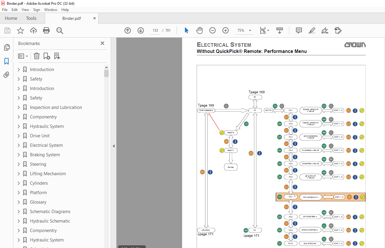
Drift testWithout QuickPickR Remote: Menu Structure – Overview
With QuickPickR Remote: Pairing Submenu
With QuickPickR Remote: Operator Menu
With QuickPickR Remote: Operator Menu
With QuickPickR Remote: Service Menu, Analyzer A1
With QuickPickR Remote: Service Menu, Analyzer A2
With QuickPickR Remote: Service Menu, Analyzer A3
With QuickPickR Remote: Service Menu, Analyzer A3
With QuickPickR Remote: Service Menu, Analyzer A2
Inputs With QuickPickR Remote:
Service Menu, Analyzer A3 Inputs With QuickPickR Remote:
Service Menu, Analyzer A5 Inputs With QuickPickR Remote:
Service Menu, Analyzer A6 Inputs With QuickPickR Remote:
Service Menu, Analyzer A8 Inputs With QuickPickR Remote:
Service Menu, Analyzer A8 Inputs With QuickPickR Remote:
Service Menu, Analyzer A8 Output With QuickPickR Remote:
Service Menu, C1 and C3 Calibration With QuickPickR Remote:
Service Menu, C2 Calibration
With QuickPickR Remote: Service Menu, F1 FeaturesWithout QuickPickR Remote: Menu Structure – Overview
With QuickPickR Remote: Pairing Submenu
With QuickPickR Remote: Operator Menu
With QuickPickR Remote: Operator Menu
With QuickPickR Remote: Service Menu,
Analyzer A1 With QuickPickR Remote:
Service Menu, Analyzer A2 With QuickPickR
Remote: Service Menu, Analyzer A3 With QuickPickR Remote:
Service Menu, Analyzer A3 With QuickPickR Remote:
Service Menu, Analyzer A2 Inputs With QuickPickR Remote:
Service Menu, Analyzer A3 Inputs With QuickPickR Remote:
Service Menu, Analyzer A5 Inputs With QuickPickR Remote:
Service Menu, Analyzer A6 Inputs With QuickPickR Remote:
Service Menu, Analyzer A8 Inputs With QuickPickR Remote:
Service Menu, Analyzer A8 Inputs With QuickPickR Remote:
Service Menu, Analyzer A8 Output With QuickPickR Remote:
Service Menu, C1 and C3 Calibration With QuickPickR Remote:
Service Menu, C2 Calibration
With QuickPickR Remote: Service Menu, F1 Features
Parameter GPC 3045/55 without QuickPick® Remote
GPC 3020 Parameter without QPR up to 08/2012
Parameter GPC 3020/40/45/50/55/60 without QPR Starting with 09/2012
With QuickPick® Remote: Calibration
Calibrating the Traction Potentiometer
Calibrating the Steering
Calibrating the Load Sensor
Without QuickPick® Remote: Calibration
With QuickPick® Remote: Check the Safety of the Laser System
With QuickPick® Remote: Adjust Laser System
Event Codes
With QuickPick® Remote: Event Code Group 100
With QuickPick® Remote: Event Code Group 200
With QuickPickR Remote: Event Code – Group 300
With QuickPick® Remote: Event Code Group 500
With QuickPick® Remote: Event Code Group 800
With QuickPick® Remote: Event Code Group 900
With QuickPick® Remote: Event Code Group 1000
Without QuickPick® Remote: Event Code Group 200
(GPC 3020 up to 08/2012) Without QuickPickR Remote: Event Code Group 300 (GPC 3020 up to 08/2012)Event Code Group 800 and 900 (From 09/2012)
Without QPR: Event Code Group 800 (All GPCs Starting with 09/2012)Without QPR: Event Code Group 900 (All GPCs Starting with 09/2012)
Without QPR: Event Code Group 1000 (All GPCs Starting with 09/2012)With QuickPick® Remote: Events with Plain Text Display
Without QuickPickR Remote: Events with Plain Text Display
Repairing the ABM Traction MotorRepairing the ABM Traction MotorMaintaining the Crown Traction Motor
Repairing the Crown Traction MotorGeneral DC Motor Maintenance InstructionsRemoving and Installing the Steer Motor
Repairing the Steer Motor
Repairing Pump MotorsBattery Information
Battery Discharge Indicator (BDI)
Replacing the Batteries
Repairing the Contactor
Perform PMT TestSchematic DiagramsHydraulic SchematicComponentry
Hydraulic SystemDrive UnitElectrical SystemCylindersBraking SystemSteering
X10_Standard_grau_en_5A417753.pdf
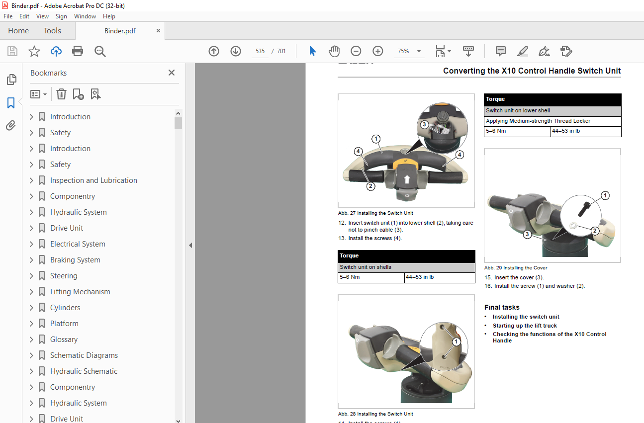
Replacing the Switch Unit of the X10 Control Handle
Previous tasks
Removing the Switch Unit
Abb. 17 Removing the Cover
1. Remove the screw (1) and washer (2).
2. Remove the cover (3).
Abb. 18 Removing the Switch Unit
3. Remove the screws (1).
Abb. 19 Removing the Switch Unit
Onnector (3)
for the fun winny maries and connecLUI (4)
10 the contro nanuit Cavic.
9. Remove the switch unit (1).
Abb. 21 Removing the Cover Cap
10. Remove the cover cap (1)
from the control handle (2)
by levering it into the small opening (arrow) with a suitable tool.
Abb. 22 Removing the Horn
11. Press the horn (1)
in and remove from the control handle (2).
12. Disconnect the connector (3)
and remove the horn (1).
Abb. 23 Removing the Cover Cap
13. Remove the cover cap (1)
from the control handle (2)
by levering it into the small opening (arrow) with a suitable tool. Abb. 24 Removing the Horn
14. Press the horn (1) in and remove from the control handle (2).
15. Disconnect the connector (3) and remove the horn (1).
Abb. 25 Removing the Control Handle
16. Remove the screw (1).
17. Carefully pull the control handle
(2) off the shells (3)
and guide the connector (4)
through the opening (arrow).
Abb. 26 Removing the Control Handle
18. Remove the screw (1).
19. Carefully pull the control handle (2)
off the shells (3)
and guide the connector (4)
through the opening (arrow).
Abb. 27 Removing the Upper Shell
20. Remove the screws (1).
IMAGES PREVIEW OF THE MANUAL:
More products