$43
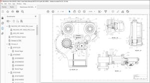
Crown Forklift IC Hamech 2012 – V47 D-4TNE98 DIESEL ENGINE Service Manual – PDF DOWNLOAD
Crown Forklift IC Hamech 2012 – V47 D-4TNE98 DIESEL ENGINE Service Manual – PDF DOWNLOAD
FILE DETAILS:
Crown Forklift IC Hamech 2012 – V47 D-4TNE98 DIESEL ENGINE Service Manual – PDF DOWNLOAD
Language : English
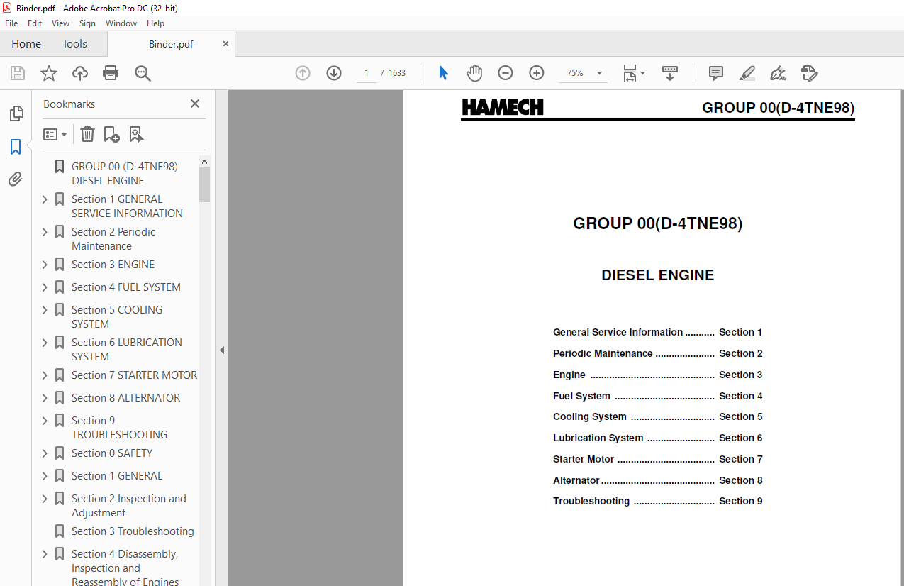
Pages :1633
Downloadable : Yes
File Type : PDF
TABLE OF CONTENTS:
Crown Forklift IC Hamech 2012 – V47 D-4TNE98 DIESEL ENGINE Service Manual – PDF DOWNLOAD
GROUP 00 (D-4TNE98) DIESEL ENGINE 1
Section 1 GENERAL SERVICE INFORMATION 3
COMPONENT IDENTIFICATION 3
LOCATION OF LABELS 3
DIESEL FUEL 4
ENGINE OIL 5
ENGINE COOLANT 7
SPECIFICATIONS 9
ENGINE SERVICE INFORMATION 11
TIGHTENING TORQUES FOR STANDARD BOLTS AND NUTS 12
STANDARD TORQUE CHART 13
Section 2 Periodic Maintenance 15
PERIODIC MAINTENANCE PROCEDURES 17
Daily 17
Every 250 Hours of Operation 19
Every 500 Hours of Operation 23
Every 1000 Hours of Operation 25
Every 2000 Hours of Operation 30
Every 4000 Hours of Operation 31
Section 3 ENGINE 33
ENGINE SERVICE INFORMATION 34
ENGINE SPECIAL TORQUE CHART 40
SPECIAL SERVICE TOOLS 41
CYlinder Head Components 46
Disassembly of Cylinder Head 47
Removal of Glow Plugs 48
Removal of Valve Cover 48
Removal of Rocker Arm Assembly 48
Disassembly of Rocker Arm Assembly 49
Removal of Cylinder Head 49
Removal of Intake / Exhaust Valves 50
Removal of Valve Guides 50
Cleaning of Cylinder Head Components 51
Inspection of Cylinder Head Components 51
Assembly of Cylinder Head 54
Assembly of Intake and Exhaust Valves 54
Assembly of Cylinder Head 55
Assembly of Rocker Arm Assembly 56
Assembly of the Valve Cover 57
Assembly of Glow Plugs 57
MEASURING AND ADJUSTING VALVE CLEARANCE 58
DRIVE TRAIN AND CAMSHAFT COMPONENTS 60
Disassembly of Drive Train andCamshaft Components 61
Removal of Oil Pan 62
Removal of Oil Sump Pump 62
Removal of Timing Gears 63
Removal of Pistons 63
Removal of Crankshaft 64
Removal of Gear Case 66
Inspection of Drive Train and Camshaft Components 67
Honing and Boring 73
Assembly of Drive Train andCamshaft Components 74
Assembly of Pistons 74
Installation of Gear Case 75
Installation of Crankshaft 75
Installation of Pistons 76
Installation of Camshaft 77
Installation of Timing Gears 77
Installation of Gear Case Cover 78
Installation of Oil Sump Pump 78
Installation of Oil Pan 78
Section 4 FUEL SYSTEM 81
FUEL SYSTEM COMPONENTS 82
FUEL SYSTEM DIAGRAM 83
STRUCTURE AND OPERATION OF FUEL INJECTION PUMP 84
PLUNGER OPERATION 88
ALL -SPEED GOVERNOR 93
STRUCTURE AND OPERATION OF TIMER 100
REMOVAL OF FUEL INJECTION PUMP 102
INSTALLATION OF THE FUEL INJECTION PUMP 105
CHECKING / ADJUSTMENT OF FUEL INJECTION TIMING 107
SERVICING THE FUEL INJECTORS 108
Section 5 COOLING SYSTEM 113
ENGINE COOLANT PUMP COMPONENTS 114
ENGINE COOLANT SYSTEMCHECK 115
DISASSEMBLY OF ENGINE COOLANTPUMP 115
CLEANING AND INSPECTION 117
ASSEMBLY OF ENGINE COOLANTPUMP 118
Section 6 LUBRICATION SYSTEM 121
LUBRICATION SYSTEM DIAGRAM 122
CHECKING ENGINE OIL PRESSURE 123
Section 7 STARTER MOTOR 127
STARTER MOTOR TROUBLESHOOTING 128
STARTER MOTOR PRECAUTIONS 129
STARTER MOTOR SERVICING 130
Section 8 ALTERNATOR 141
ALTERNATOR TROUBLESHOOTING 142
ALTERNATOR COMPONENTS 143
Section 9 TROUBLESHOOTING 157
TROUBLESHOOTING BY MEASURING COMPRESSION PRESSURE 158
QUICK REFERENCE TABLE FOR TROUBLESHOOTING 160
Section 0 SAFETY 165
Safety Precautions 166
SERVICE AREA 166
WORK – WEAR (GARMENTS) 166
TOOLS 167
GENUINE PARTS and MATERIALS 167
FASTENER TORQUE 167
Electrical 168
WASTE MANAGEMENT 168
FURTHER PRECAUTIONS 169
Precautions for Service Work 170
How to Read this Manual 170
Section 1 GENERAL 173
Fuel Oil, Lubricating Oil andCooling Water 176
Exhaust gas emission regulation 178
Section 2 Inspection and Adjustment 183
Periodic Inspection and Maintenance Procedure 184
Inspection every 1,000 hours or one year 195
Section 3 Troubleshooting 211
Section 4 Disassembly, Inspection and Reassembly of Engines 219
Complete disassembly 224
Cylinder Head: Disassembly, Inspection and Reassembly 229
Gear Train and Camshaft 240
Cylinder Block 246
Section 5 LUBRICATION SYSTEM 261
Section 6 COOLING SYSTEM 265
Section 7 FUEL INJECTION PUMP/GOVERNOR 267
Section 8 ALTERNATOR 273
Section 9 ELECTRIC WIRING 277
Section 10 SERVICE STANDARDS 282
Engine Body 283
Gear train and camshaft 284
Cylinder block 285
Lubricating Oil System (Trochoid Pump) 288
Section 11 TIGHTENING TORQUE for BOLTS and NUTS 290
Section1 Safety 294
Section2 Lifting, Jacking, and Blocking the Truck 298
Safe Parking 299
Lifting, Blocking, and Jacking Points 299
Raising Drive Wheels Off Floor 299
Raising Truck with A Hoist 300
Blocking the Upright In Raised Position 301
Raising Rear of Truck 301
Raising Entire Truck 302
Shipping Tie-Down Instructions 303
Section3 Towing 304
GROUP 00 (L-GM) ENGINE (GM 30 LPG) 308
Section 1 Specifications and Information 310
Section 2 Diagnostic Information and Procedures 314
Section 3 Engine Removal and Installation 318
Section 4 Description and Operation 378
Section 1 General Information 386
Section 2 Specification and Troubleshooting 394
Specifications 0
Tightening Torque 0
Compression Pressure Inspection 0
Valve Clearance and Adjustment 0
Troubleshooting 0
Special service tools 0
Section 3 Disassembly and Reassembly 410
TIMING SYSTEM 0
Removal 0
Inspection 0
Installation 0
CYLINDER HEAD ASSEMBLY 0
Removal 0
Disassembly 0
Inspection 0
Cylinder Head 0
Valve And Valve Spring 0
MLA 0
Camshaft 0
Reassembly 0
CYLINDER BLOCK ASSEMBLY 0
Disassembley 0
Inspection 0
Connecting Rod And Crankshaft 0
Cylinder Block 0
Piston And Rings 0
Piston Pins 0
Reassembly 0
COOLING SYSTEM 0
Removal 0
Water pump 0
Thermostat 0
Inspection 0
Water pump 0
Thermostat 0
Installation 0
Thermostat 0
Troubleshooting 0
Water pump 0
Thermostat 0
Intake manifold 0
Removal 0
Installation 0
Exaust manifold 0
Removal 0
Installation 0
Section 4 Lubrication System 458
Oil Pump 0
Engine Oil 0
Oil Pressure Switch 0
Selection Of Engine Oil 0
Section 5 Electrical System 464
Specification 0
Trouble Shooting 0
Special Service Tool 0
Ignition system 0
Description 0
Repair procedures 0
Spark Test 0
On-vehicle Inspection 0
Inspect Spark Plug 0
Inspect Ignition Coil 0
Charging system 0
Inspect Drive Belt 0
Inspect Charging System 0
Output Current Test 0
Regulated Voltage Test 0
Alternator 0
Starting system 0
Inspection 0
Description 0
Starter 0
Removal 0
Disassembly 0
Inspection 0
Armature Inspection And Test 0
Inspect Starter Brush 0
Starter Brush Holder Test 0
Inspect Overrunning Clutch 0
Cleaning 0
Starter relay 0
Section 6 Emission Control System 486
PCV(positive crankcase ventilation) VALVE 0
FUEL SYSTEM 0
Specifications 0
Sensor 0
Tightening torques 0
Troubleshooting 0
Basic inspection procedure 0
Engine control system 0
MAPS (Manifold Absolute Pressure Sensor) 0
IATS (Intake Air Temperature Sensor) 0
ECTS (Engine Coolant Temperature Sensor) 0
CMPS (Camshaft Position Sensor) 0
CKPS (Crankshaft Position Sensor) 0
HO2S (Heated Oxygen Sensor) 0
KS (Knock Sensor) 0
Injector 0
Section 1 General Information 506
Section 2 Maintenance 508
Section 3 LPG Fuel System 516
Section 4 Fuel System Diagnosis 522
Section 5 Electrical Section 538
Diagnostic Trouble Codes (DTCs) 565
OBD System Check/MIL (MalfunctionIndicator Lamp) 570
HVS Ignition Control System Diagnostics 571
Ignition Control System DiagnosticChart 572
Section 6 Definitions 724
Section 1 LPG Fuel System 732
LPG FUEL SYSTEM 732
Section 2 Fuel System Component Details 734
Description of Regulator/Vaporizer Operating States 736
Liquid-Phase Filter & Shutoff Valve 738
Fuel Rail 739
Gaseous Fuel Filter 740
Engine Control Unit 741
Wire Harness 744
Emissions Catalyst 746
Oxygen Sensors 747
Ignition Control System 749
Power Transistors 749
Locations of Major Sensors & Components 750
Section 3 Recommended Maintenance 752
General Maintenance Guideline 753
Fuel System Leak Testing 754
General Fluid Leaks 754
Coolant System 754
Electrical System & Harness 754
Ignition System 757
LPG Regulator Service 757
LPG Shutoff Valve – Option 1, Valtek 760
LPG Liquid Filter – Option 1, Valtek 760
Maintenance Kit for LPG Liquid Filter 761
LPG Shutoff Valve – Option 2, AFC 762
LPG Rail & Injectors 763
Throttle Body & Intake Tubing 765
TMAP Sensor 765
Exhaust System & Catalyst 765
Section 4 Diagnostic Trouble Codes (DTC) 766
SUPPORTED DTCS 769
Section 5 General Trouble Shooting 776
Engine cranks but will not start 776
Engine does not provide expected power output, slow to accelerate, stalls when lifting load 777
Engine speed hunting at idle and other speed and load conditions 778
Engine backfires 779
Engine knocking 780
Engine run-on after shut down 781
Engine misfires 781
Poor fuel economy 782
High idle speed (above the set point of 750 rpm) 782
Engine knocking 783
Section 6 TROUBLE SHOOTING BY DTC 784
Section 7 DIAGNOSTIC SERVICE TOOL 810
Section 1 General Information 828
Section 2 Maintenance 830
Section 3 LPG Fuel System 838
Section 4 Fuel System Diagnosis 844
Section 5 Electrical Section 860
Diagnostic Trouble Codes (DTCs) 887
OBD System Check/MIL (MalfunctionIndicator Lamp) 892
HVS Ignition Control System Diagnostics 893
Ignition Control System DiagnosticChart 894
Section 6 Definitions1046
Section 1 Engine Cooling System 1054
Section 2 Troubleshooting 1056
Section 3 Testing and Maintenance 1058
Engine Coolant Level Check1059
Adding Coolant1060
Cooling System Inspection1060
Cooling System Tests1061
Testing the Radiator Cap1061
Testing Radiator and Cooling System1062
Testing the Thermostat1062
Engine Coolant Change1062
Draining Radiator and Cooling System1062
Cleaning and Flushing Cooling System1063
Filling Cooling System1063
Section 4 Engine Cooling System and Alternator Belt Service 1066
Belt Checks1067
Gas/LPG Truck Belt Removal1067
Fan Drive Belt Removal1067
Alternator/Water Pump Belt Removal1068
Gas/LPG Truck Belt Replacement1068
Alternator/Water Pump Belt Replacement (V47)1068
Fan Drive Belt Replacement1068
Alternator/Water Pump Belt Tension (Gas/LPG Engines)1069
Fan Drive Belt Tension (Gas/LPG Engines)1069
Diesel truck fan drive belt replacement1070
Section 5 Radiator Removal and Replacement 1052
Radiator Removal1073
Radiator Replacement1075
Section 1 Specifications and Description1080
Section 2 Intake System Troubleshooting1082
Section 3 Intake System Service1084
Section 4 Exhaust Systems1088
Section 1 Cautions for working on the electrical system1096
Section 2 Electrical system Specifications and features1098
Section 3 Electrical Circuit Diagram & Electrical Parts Arrangement1100
VL30-VL40s WIRING DIAGRAM1101
INSTALL ELECTRICAL COMPONENT & HARNESS MAIN1107
VL30-40s LPG Tier 41110
VL30-40s Diesel Tier 31111
VL30-40s Diesel Tier 31113
VL30-40s Diesel Tier 31106
VL40-VL70 WIRING DIAGRAM1116
VL40-VL70 Diesel Tier 31119
INSTALL ELECTRICAL COMPONENTS & HARNESS MAIN1122
VL40-70 LPG Tier 41125
VL40-70 Diesel Tier 31130
VL40-70 Diesel Tier 31133
Section 4 Instrument Pod1138
1 Display Monitor1139
2 Explanation of function1140
3 Major function of truck1142
4 Functional setting and operation1144
41 Operating method for mode switch1144
42 Menu mode composition chart1145
# Menu Mode (Tree structure)1147
43 Menu mode check and adjusting method1148
44 Model set1150
45 Error history1150
46 Password change1151
47 Set on communication for option equipment1153
48 Optional function setting1153
49 DATE setting1161
5 Fault diagnosis1162
51 Self diagnostic function1162
52 Management of fault history1162
53 Error code1163
Section 5 Electrical Components Specification and Operation1164
Battery1165
Engine Accessories1166
Alternator1166
Starting Motor1167
Water Temp Sender1168
Switch-Eng Oil Pressure1169
LPG Pressure Switch1170
Switch-T/M Temp1171
Fuel Sender1172
Switches1173
Start Switch1173
Switch Fow & Rev1174
Switch – directional Indicator1175
Brake Stop Switch1176
Parking Brake Switch1177
Seat Switch1178
General Electrical Parts1179
Fuse / Relay Box1179
Engine Stop Relay1180
Flash Unit1181
Start and Preheat Relays1182
Horn1183
Backup Alarm1184
Lights1185
Lamp-Work1185
Lamp-Indicator1186
Combination Lamp1187
Lamp-Beacon1188
Directional Disable Function1189
1 Description of Operating the Neutral Shift Function1189
2 Description of Engine Shutdown Function action1190
Section 6 Troubleshooting of Electrical System1192
Fuel Gauge Malfunction1193
Hourmeter Malfunction1194
Coolant Temp Gage Malfunction1195
Transaxle Oil Malfunction1196
Engine Oil Gage Malfunction1197
Alternator Charge Malfunction1198
Preheat Plug Malfunction1199
Parking Brake Malfunction1200
Work Lamp Switch Malfunction1201
Rear Work Lamp Switch1202
All of Instrument Pod Lamps Fails to Turn On1203
Failure to Drive1204
Failure to engine shut down (Diesel-tier2)1205
Failure to engine shut down (GAS/LPG)1206
Failure to Start (GAS/LPG)1207
Failure to Start (Diesel)1208
Failure to Start (Diesel-Tier2)1209
Section 1 Specifications and Description1212
Section 2 Cushion Wheels and Tires1214
Section 3 Pneumatic Wheels and Tires1218
Pneumatic Tire Maintenance Precaution1219
General Tire Maintenance, Inspection, and Repair1220
Wheel Dismounting and Remounting1221
Drive and Steer Wheel Dismounting1221
Drive and Steer Wheel Remounting1222
Dual-Drive Wheel Dismounting(V47)1223
Dual-Drive Wheel Remounting(V47)1223
Wheel Disassembly and Tire Removal1224
Tire Replacement and Wheel Reassembly1226
Tire-to-Wheel Mounting1227
Filling Tires with Air1228
Filling Tires with Nitrogen1228
Checking and Adjusting Tire Pressure1229
Split-Rim Wheel Assemblies(V47)1230
Section 1 Braking / Inching System Specifications and Description1234
NOTE1234
Specifications1234
General Description1234
Service Brake and Inching System Arrangement1235
Inching Operation1236
Braking Operation1236
Service Requirements1236
Section 2 Service Brake Troubleshooting1238
Section 3 Brake/Inching Pedals and Linkages Adjustments1240
Section 4 Brake System Bleeding1244
Section 5 Brake Master Cylinder Service1246
Section 6 Service Brake Adjustment and Overhaul1250
External Inspection1250
Shoe-to-Drum Gap Adjustment1250
Internal Inspection and Repair1251
Brake Drum Removal and Replacement1251
Inspection1251
Brake Shoe Removal1251
Brake Shoe Replacement1251
Cylinder Removal and Replacement1252
Adjuster Removal and Replacement1252
Lubrication1252
Wheel Cylinder Overhaul1253
Operational Explanation of the Auto Adjuster1254
Section 7 Parking Brake Service1256
Operation1256
Adjustment1256
Removal and Replacement1256
Parking Brake Cable Removal and Installation1258
Section 1 Steering System Specifications and Description1262
Section 2 Steering System Troubleshooting1264
Section 3 Steering Column and Component Removal and Replacement 0
Steering Column and Component Removal 0
Ignition Switch Removal 0
Hand Wheel, Horn Contact Ring, and Directional Control Assembly Removal 0
Column Tilt Lock Assembly Removal 0
Steering Gear and Lower Steering Column Removal 0
Steer Column and Component Replacement 0
Steering Gear and Lower Steering Column Replacement 0
Column Tilt Lock Assembly Replacement 0
Directional Control Assembly Reassembly 0
Directional Control Assembly and Ignition Switch Replacement 0
Steering Hand Wheel Replacement 0
Section 4 Steering System Relief Pressure Check and Adjustment 0
Section 5 Steering Gear Overhaul1280
Disassembly1281
Parts Inspection1283
Reassembly1283
Section 1 Steer Axle Specifications and Description 0
Section 2 Steer Axle Wheel Bearing Maintenance and Adjustment1292
Section 3 Steer Axle Removal and Replacement 0
Steer Axle Removal 0
Steer Axle Replacement 0
Section 4 Steer Axle Overhaul1302
Steer Axle Disassembly1303
Parts Inspection1304
Steer Axle Reassembly1304
Section 5 Steer Cylinder Removal and Replacement1306
Steer Cylinder Removal1306
Parts Inspection1307
Steer Cylinder Replacement1307
Section 6 Steer Cylinder Overhaul1310
Preparation for Steer Cylinder Disassemblyand Overhaul1311
Steer Cylinder Disassembly1311
Parts Inspection1311
Steer Cylinder Reassembly1312
Section 1 Hydraulic Sump, Filters, and Pump Specifications and Description 0
Section 2 Main Hydraulic Pump Troubleshooting1320
Section 3 Hydraulic Filters and Fluid Maintenance and Change 0
Section 4 Hydraulic Pump Removal and Replacement 0
Section 5 Hydraulic Pump Overhaul(Hanil Pump)-V471328
Pump Disassembly1329
Steering Priority and Steering Pressure Relief Valve Disassembly1332
Pump Reassembly1333
Steering Priority and Relief Valve Reassembly1334
Section 6 Hydraulic Pump Overhaul(Jinsung Pump)-V341338
Disassembly and Assembly1339
Inspection and Assessment1340
Trouble shooting1342
Start-up1343
Section 1 Hydraulic Control Valve/Lift Circuit Specifications and Description 0
Section 2 Hydraulic System Schematics1350
Section 3 Hydraulic System Troubleshooting1352
Section 4 Hydraulic System Pressure Checks and Adjustments 0
Relief Pressure Check 0
Main and Auxiliary Pressure Relief Adjustment 0
Flow Control Adjustment 0
Section 5 Hydraulic Control Valve Removal and Replacement1358
Hydraulic Control Valve Removal1359
Hydraulic Control Valve Replacement1360
Operational Checks1361
Section 6 Hydraulic Control Valve Overhaul For HANIL Valve (V47)1362
Preparation for Disassembly1362
Disassembly1363
Cleaning, Inspection, and Repair1364
Reassembly1365
Relief Valve Settings1365
Section 7 Hydraulic Control Valve Overhaul For EATON Valve (V34)1366
Precautions1366
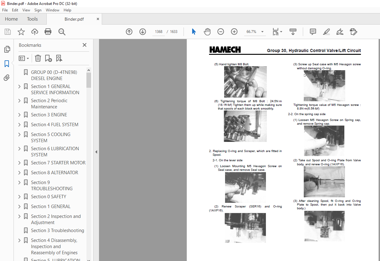
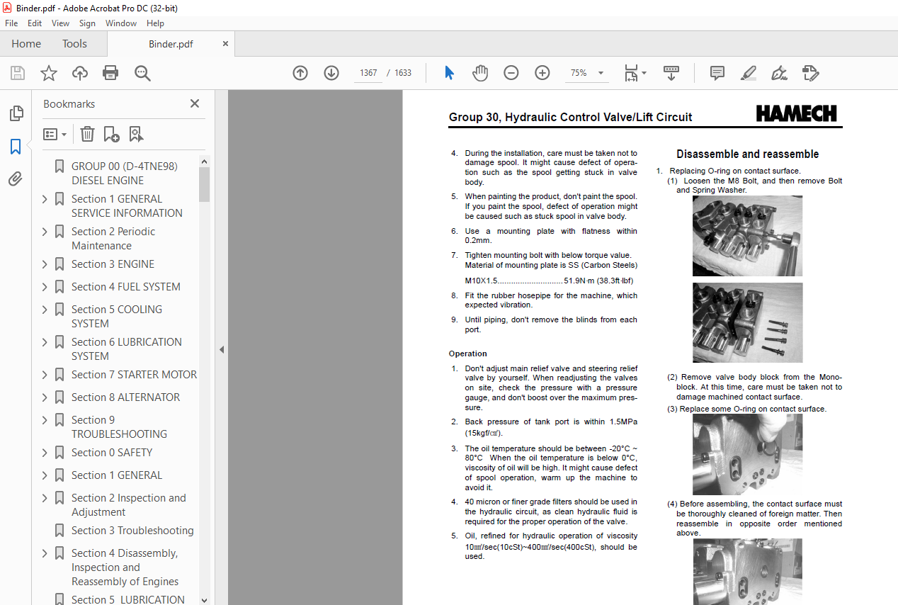
Disassemble and reassemble1367
Trouble shooting1370
Section 1 Tilt Cylinder Specifications and Description1374
Section 2 Tilt Cylinder Checks and Adjustments1376
Section 3 Tilt Cylinder Removal and Replacement 0
Tilt Cylinder Removal 0
Parts Inspection 0
Tilt Cylinder Replacement 0
Section 4 Tilt Cylinder Overhaul 0
Preparation For Disassembly 0
Disassembly 0
Inspection 0
Reassembly 0
Section 1 Upright Specifications and Description1390
General Specifications1390
Cylinder Types1390
Drift1390
Fastener and Fitting Torque Specifications1391
Service Intervals1391
Description1391
Section 2 Troubleshooting1406
Upright noise1406
No lift, tilt, or auxiliary function1406
No lift function but tilt operates1406
Load cannot be lifted to maximum height1407
Lift speed sluggish1407
Lowering speed sluggish1407
Load bounces excessively when lowering1407
Upright mis-staging (TSU lifting)1407
Upright mis-staging (TSU lowering)1408
Upright mis-staging (Standard and Hi-Lo upright lowering)1408
External leakage on primary cylinder1408
External leakage on lift (Standard) and secondary cylinder (TSUs and Hi-Lo)1409
Section 3 Upright Inspection1410
Basic Visual Inspection1411
Extended Inspection1412
Forks1412
Lift Chains1413
Carriage and Upright Weldments1414
Carriage and Upright Rollers1415
Cylinders1417
Hydraulic Plumbing1419
Upright Drift1419
Trunnion Bearings1420
Section 4 Carriage and Upright Roller Clearance Checks and Shim Adjustments1422
Introduction1422
Roller Side Clearance Checks1425
Internal Thrust Roller Adjustment(V47)1427
Oversize Rollers1428
Lift Roller Shimming1428
Carriage Roller Shimming1429
Upright Roller Shimming1429
Overshimming1432
Section 5 Cylinder Removal, Shimming, Overhaul, and Replacement1434
Cylinder Types1434
Lift Cylinder Shimming Procedure1434
Primary Cylinder Removal and Replacement (Hi-Lo & TSU)1435
Lift and Secondary Cylinder Removal and Replacement1436
Cylinder Overhaul1437
Section 6 Upright Chain Inspection, Adjustment, and Replacement1442
Periodic Inspections1444
Elongation1444
Edge Wear1444
Turning or Protruding Pins1444
Cracked Plates1444
Ultimate Strength Failure1445
Tight Joints1445
Chain Length Adjustments1446
Chain Lubrication1448
Chain Removal and Replacement1448
General Guidelines1448
Lift Chains (Standard and TSUs)1449
Primary Cylinder/Carriage Chains (TSU and Hi-Lo)1449
Other Chain Service Notes1450
Section 7 Fork and Carriage Removal and Replacement1452
Fork Removal1452
Fork Replacement1452
Carriage Removal1453
Carriage Replacement1454
Section 8 Upright Removal and Replacement1458
Upright Removal1459
Upright Replacement1460
Section 1 Counterweight Specifications and Description1464
Section 2 Counterweight Removal and Replacement1466
Section 3 Overhead Guard/Operator’s Cell Removal and Replacement1470
Section 4 Floorboard, Cowls, and Seat Deck Removal and Replacement1472
Floor Plate Removal and Replacement1473
Cowl Removal and Replacement1473
Radiator Cover Removal and Replacement1474
Operator’s Seat Deck Removal and Replacement1474
Section 5 Operator’s Seat Removal and Replacement1478
Section 1 Nameplates and Decals1484
Truck Data and Capacity Plate1485
Operator Safety Warning Plate1485
General Safety Decal1486
Seat Belt/Tip-Over Warning Decal1487
Hand Safety Warning Decal1487
Keep Away from Forks Decal1487
Fan Warning Decal1487
Nameplate, Decal Locations1488
Section 2 General Specifications1490
Weights and Performance Specifications1491
Capacities1491
Truck Weights and Axle Weights1491
Parking Brake Test1491
Maximum Gradeability1492
Drawbar Pull1492
Travel Speeds1492
Turning Radius (outside)1492
Critical Fastener Torque Specifications1493
Group Specifications1494
Group 00, V34 LPG Engine Specifications1494
Group 00, V47 LPG Engine Specifications1494
Group 00(D), V47 – 4TNE98 Diesel Engine Specifications1495
Group 01, Cooling System Specifications1496
Group 02(LP), LPG Fuel System Specifications1496
Group 03, Intake and Exhaust Systems Specifications1496
Group 06(S), Standard Transaxle Specifications1496
Group 13, Instrument Pod & Electrical System Specifications1497
Group 22, Wheels and Tires Specifications1497
Group 23(G) brake/Inching System Specifications (Standard Transaxle)1498
Group 25, Steering Column and Gear Specifications1498
Group 26, Steer Axle Specifications1498
Group 29, Hydraulic Sump, Filters, and Pump Specifications1499
Group 30, Hydraulic Valve/Lift Circuit Specifications1499
Group 32, Tilt Cylinders Specifications1500
Group 34, Upright Specifications1500
Lift Speeds, Upright1501
Group 38, Counterweight and Chassis Specifications1501
Drift, Lift and Tilt Cylinders1501
Section 3 Hydraulic Fitting Tightening Procedure1502
Section1 Maintenance Schedulespdf1506
Maintenance Schedules1506
“Periodic Service” and “Planned Maintenance”1506
Determining Maintenance Intervals1506
Service Chart/Lubrication Points1507
Recommended Periodic Service Schedule1507
Section2 The Planned Maintenance Programpdf1512
Introduction to Planned Maintenance1513
PM Intervals1513
The PM Form1513
The Basic PM Procedures1513
The Recommended PM Task Chart1514
Listed by Service Manual Group1514
Visual Inspection1515
Functional Tests1517
Air Cleaning the Truck1519
Truck Chassis Inspection and Lubrication1520
Upright and Tilt Cylinder Lubrication1520
Lift Chain Lubrication1520
Under-the-Hood Inspection1520
Fluid Checks1520
Stall Test1521
Cranking Voltage Test1521
Critical Fastener Torque Checks1521
The Planned Maintenance Program1512
Section 1 Transaxle Specifications and Description 0
Construction 0
hydraulic circuit 0
SERVICE MAINTENANCE 0
Specification 0
Pressure specification 0
Pressure check points 0
Service brake adjustment 0
Section 2 Transaxle Disassembly1532
Wheel End1534
Brake Assembly Removal1536
Separation of Converter Housing and Adaptor Plate1537
Stator Support Removal From Adaptor Plate1538
Clutch Assembly, idler Gear & Pinion Shaft Removal1538
Section 3 Transaxle Reassembly1542
DIFFERENTIAL1543
Wheel End Final Assembly1551
Install brake assemblies1552
CLUTCH ASSEMBLY1554
Transmission assembly1556
Section 1 Transaxle Specifications and Description1562
Specifications1563
Description1565
Torque Converter1565
Charging Pump1566
Transmission1566
Forward/Reverse Clutch Packs1566
Solenoid Valves1566
Transaxle Control Valve1567
Differential1568
Drive Axle1569
Operation1570
Transaxle Hydraulic Schematic1572
Sectional View Along Turbine Shaft1573
Sectional View Along Drive Axle1574
Section 2 Transaxle Troubleshooting1576
Checks1578
Fluid Level Check1578
Fluid Leakage Checks1578
General Mechanical/Electrical Checks1578
Solenoid Valve Electrical Checks1578
Stall RPM Test1579
Transaxle Pressure Checks1579
Section 3 Transaxle Oil and Filter 1582
Section 4 Transaxle Oil Cooler1586
Flow Check1586
Pressure Check1586
Oil Cooler Removal1587
Oil Cooler Installation1588
Section 5 Transaxle Removal and Replacement1590
Transaxle Removal1591
Transaxle Replacement1593
Section 6 Transaxle Overhaul1596
General Practices to Follow1597
Disassembling Components1597
Cleaning Parts1597
Inspecting Parts1598
Repairing and Replacing Parts1598
Reassembling Components1599
Overhaul Procedures1600
Transaxle Disassembly1600
Differential Overhaul1608
Clutch Overhaul1609
Transaxle Control Valve Overhaul1613
Section 7 Drive Axle Ends Overhaul1628
Section 8 Transaxle Control Valve Overhaul1632
IMAGES PREVIEW OF THE MANUAL:
More products