$41
Crown Forklift IC Hamech D-4TNE98 DIESEL ENGINE Service Manual – PDF DOWNLOAD
Crown Forklift IC Hamech D-4TNE98 DIESEL ENGINE Service Manual – PDF DOWNLOAD
FILE DETAILS:
Crown Forklift IC Hamech D-4TNE98 DIESEL ENGINE Service Manual – PDF DOWNLOAD
Language : English
Pages :1291
Downloadable : Yes
File Type : PDF
TABLE OF CONTENTS:
Crown Forklift IC Hamech D-4TNE98 DIESEL ENGINE Service Manual – PDF DOWNLOAD
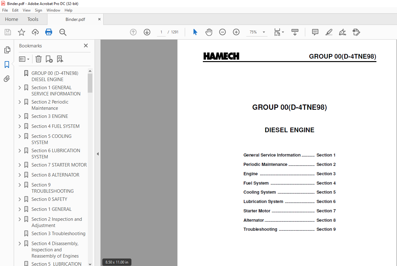
GROUP 00 (D-4TNE98) DIESEL ENGINE 1
Section 1 GENERAL SERVICE INFORMATION 3
COMPONENT IDENTIFICATION 3
LOCATION OF LABELS 3
DIESEL FUEL 4
ENGINE OIL 5
ENGINE COOLANT 7
SPECIFICATIONS 9
ENGINE SERVICE INFORMATION 11
TIGHTENING TORQUES FOR STANDARD BOLTS AND NUTS 12
STANDARD TORQUE CHART 13
Section 2 Periodic Maintenance 15
PERIODIC MAINTENANCE PROCEDURES 17
Daily 17
Every 250 Hours of Operation 19
Every 500 Hours of Operation 23
Every 1000 Hours of Operation 25
Every 2000 Hours of Operation 30
Every 4000 Hours of Operation 31
Section 3 ENGINE 33
ENGINE SERVICE INFORMATION 34
ENGINE SPECIAL TORQUE CHART 40
SPECIAL SERVICE TOOLS 41
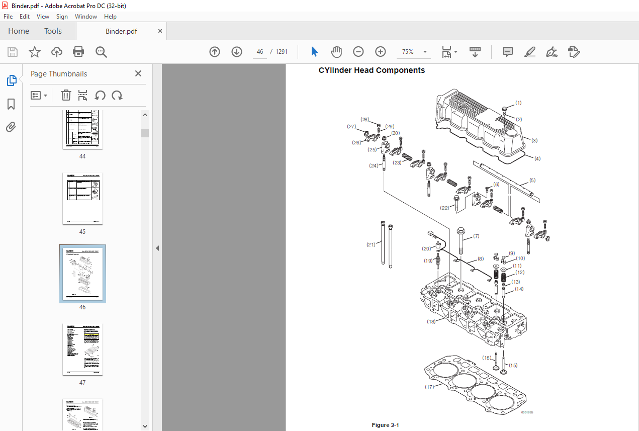
CYlinder Head Components 46
Disassembly of Cylinder Head 47
Removal of Glow Plugs 48
Removal of Valve Cover 48
Removal of Rocker Arm Assembly 48
Disassembly of Rocker Arm Assembly 49
Removal of Cylinder Head 49
Removal of Intake / Exhaust Valves 50
Removal of Valve Guides 50
Cleaning of Cylinder Head Components 51
Inspection of Cylinder Head Components 51
Assembly of Cylinder Head 54
Assembly of Intake and Exhaust Valves 54
Assembly of Cylinder Head 55
Assembly of Rocker Arm Assembly 56
Assembly of the Valve Cover 57
Assembly of Glow Plugs 57
MEASURING AND ADJUSTING VALVE CLEARANCE 58
DRIVE TRAIN AND CAMSHAFT COMPONENTS 60
Disassembly of Drive Train andCamshaft Components 61
Removal of Oil Pan 62
Removal of Oil Sump Pump 62
Removal of Timing Gears 63
Removal of Pistons 63
Removal of Crankshaft 64
Removal of Gear Case 66
Inspection of Drive Train and Camshaft Components 67
Honing and Boring 73
Assembly of Drive Train andCamshaft Components 74
Assembly of Pistons 74
Installation of Gear Case 75
Installation of Crankshaft 75
Installation of Pistons 76
Installation of Camshaft 77
Installation of Timing Gears 77
Installation of Gear Case Cover 78
Installation of Oil Sump Pump 78
Installation of Oil Pan 78
Section 4 FUEL SYSTEM 81
FUEL SYSTEM COMPONENTS 82
FUEL SYSTEM DIAGRAM 83
STRUCTURE AND OPERATION OF FUEL INJECTION PUMP 84
PLUNGER OPERATION 88
ALL -SPEED GOVERNOR 93
STRUCTURE AND OPERATION OF TIMER 100
REMOVAL OF FUEL INJECTION PUMP 102
INSTALLATION OF THE FUEL INJECTION PUMP 105
CHECKING / ADJUSTMENT OF FUEL INJECTION TIMING 107
SERVICING THE FUEL INJECTORS 108
Section 5 COOLING SYSTEM 113
ENGINE COOLANT PUMP COMPONENTS 114
ENGINE COOLANT SYSTEMCHECK 115
DISASSEMBLY OF ENGINE COOLANTPUMP 115
CLEANING AND INSPECTION 117
ASSEMBLY OF ENGINE COOLANTPUMP 118
Section 6 LUBRICATION SYSTEM 121
LUBRICATION SYSTEM DIAGRAM 122
CHECKING ENGINE OIL PRESSURE 123
Section 7 STARTER MOTOR 127
STARTER MOTOR TROUBLESHOOTING 128
STARTER MOTOR PRECAUTIONS 129
STARTER MOTOR SERVICING 130
Section 8 ALTERNATOR 141
ALTERNATOR TROUBLESHOOTING 142
ALTERNATOR COMPONENTS 143
Section 9 TROUBLESHOOTING 157
TROUBLESHOOTING BY MEASURING COMPRESSION PRESSURE 158
QUICK REFERENCE TABLE FOR TROUBLESHOOTING 160
Section 0 SAFETY 165
Safety Precautions 166
SERVICE AREA 166
WORK – WEAR (GARMENTS) 166
TOOLS 167
GENUINE PARTS and MATERIALS 167
FASTENER TORQUE 167
Electrical 168
WASTE MANAGEMENT 168
FURTHER PRECAUTIONS 169
Precautions for Service Work 170
How to Read this Manual 170
Section 1 GENERAL 173
Fuel Oil, Lubricating Oil andCooling Water 176
Exhaust gas emission regulation 178
Section 2 Inspection and Adjustment 183
Periodic Inspection and Maintenance Procedure 184
Inspection every 1,000 hours or one year 195
Section 3 Troubleshooting 211
Section 4 Disassembly, Inspection and Reassembly of Engines 219
Complete disassembly 224
Cylinder Head: Disassembly, Inspection and Reassembly 229
Gear Train and Camshaft 240
Cylinder Block 246
Section 5 LUBRICATION SYSTEM 261
Section 6 COOLING SYSTEM 265
Section 7 FUEL INJECTION PUMP/GOVERNOR 267
Section 8 ALTERNATOR 273
Section 9 ELECTRIC WIRING 277
Section 10 SERVICE STANDARDS 282
Engine Body 283
Gear train and camshaft 284
Cylinder block 285
Lubricating Oil System (Trochoid Pump) 288
Section 11 TIGHTENING TORQUE for BOLTS and NUTS 290
GROUP 00 (L-GM) ENGINE (GM 30 LPG) 292
Section 1 Specifications and Information 294
Section 2 Diagnostic Information and Procedures 298
Section 3 Engine Removal and Installation 302
Section 4 Description and Operation 362
Section 1 General Information 370
Section 2 Specification and Troubleshooting 378
Specifications 0
Tightening Torque 0
Compression Pressure Inspection 0
Valve Clearance and Adjustment 0
Troubleshooting 0
Special service tools 0
Section 3 Disassembly and Reassembly 394
TIMING SYSTEM 0
Removal 0
Inspection 0
Installation 0
CYLINDER HEAD ASSEMBLY 0
Removal 0
Disassembly 0
Inspection 0
Cylinder Head 0
Valve And Valve Spring 0
MLA 0
Camshaft 0
Reassembly 0
CYLINDER BLOCK ASSEMBLY 0
Disassembley 0
Inspection 0
Connecting Rod And Crankshaft 0
Cylinder Block 0
Piston And Rings 0
Piston Pins 0
Reassembly 0
COOLING SYSTEM 0
Removal 0
Water pump 0
Thermostat 0
Inspection 0
Water pump 0
Thermostat 0
Installation 0
Thermostat 0
Troubleshooting 0
Water pump 0
Thermostat 0
Intake manifold 0
Removal 0
Installation 0
Exaust manifold 0
Removal 0
Installation 0
Section 4 Lubrication System 442
Oil Pump 0
Engine Oil 0
Oil Pressure Switch 0
Selection Of Engine Oil 0
Section 5 Electrical System 448
Specification 0
Trouble Shooting 0
Special Service Tool 0
Ignition system 0
Description 0
Repair procedures 0
Spark Test 0
On-vehicle Inspection 0
Inspect Spark Plug 0
Inspect Ignition Coil 0
Charging system 0
Inspect Drive Belt 0
Inspect Charging System 0
Output Current Test 0
Regulated Voltage Test 0
Alternator 0
Starting system 0
Inspection 0
Description 0
Starter 0
Removal 0
Disassembly 0
Inspection 0
Armature Inspection And Test 0
Inspect Starter Brush 0
Starter Brush Holder Test 0
Inspect Overrunning Clutch 0
Cleaning 0
Starter relay 0
Section 6 Emission Control System 470
PCV(positive crankcase ventilation) VALVE 0
FUEL SYSTEM 0
Specifications 0
Sensor 0
Tightening torques 0
Troubleshooting 0
Basic inspection procedure 0
Engine control system 0
MAPS (Manifold Absolute Pressure Sensor) 0
IATS (Intake Air Temperature Sensor) 0
ECTS (Engine Coolant Temperature Sensor) 0
CMPS (Camshaft Position Sensor) 0
CKPS (Crankshaft Position Sensor) 0
HO2S (Heated Oxygen Sensor) 0
KS (Knock Sensor) 0
Injector 0
Section 1 LPG Fuel System 492
LPG FUEL SYSTEM 492
Section 2 Fuel System Component Details 494
Description of Regulator/Vaporizer Operating States 496
Liquid-Phase Filter & Shutoff Valve 498
Fuel Rail 499
Gaseous Fuel Filter 500
Engine Control Unit 501
Wire Harness 504
Emissions Catalyst 506
Oxygen Sensors 507
Ignition Control System 509
Power Transistors 509
Locations of Major Sensors & Components 510
Section 3 Recommended Maintenance 512
General Maintenance Guideline 513
Fuel System Leak Testing 514
General Fluid Leaks 514
Coolant System 514
Electrical System & Harness 514
Ignition System 517
LPG Regulator Service 517
LPG Shutoff Valve – Option 1, Valtek 520
LPG Liquid Filter – Option 1, Valtek 520
Maintenance Kit for LPG Liquid Filter 521
LPG Shutoff Valve – Option 2, AFC 522
LPG Rail & Injectors 523
Throttle Body & Intake Tubing 525
TMAP Sensor 525
Exhaust System & Catalyst 525
Section 4 Diagnostic Trouble Codes (DTC) 526
SUPPORTED DTCS 529
Section 5 General Trouble Shooting 536
Engine cranks but will not start 536
Engine does not provide expected power output, slow to accelerate, stalls when lifting load 537
Engine speed hunting at idle and other speed and load conditions 538
Engine backfires 539
Engine knocking 540
Engine run-on after shut down 541
Engine misfires 541
Poor fuel economy 542
High idle speed (above the set point of 750 rpm) 542
Engine knocking 543
Section 6 TROUBLE SHOOTING BY DTC 544
Section 7 DIAGNOSTIC SERVICE TOOL 570
Section 1 General Information 588
Section 2 Maintenance 590
Section 3 LPG Fuel System 598
Section 4 Fuel System Diagnosis 604
Section 5 Electrical Section 620
Diagnostic Trouble Codes (DTCs) 647
OBD System Check/MIL (MalfunctionIndicator Lamp) 652
HVS Ignition Control System Diagnostics 653
Ignition Control System DiagnosticChart 654
Section 6 Definitions 806
Section 1 Engine Cooling System 814
Section 2 Troubleshooting 816
Section 3 Testing and Maintenance 818
Engine Coolant Level Check 819
Adding Coolant 820
Cooling System Inspection 820
Cooling System Tests 821
Testing the Radiator Cap 821
Testing Radiator and Cooling System 822
Testing the Thermostat 822
Engine Coolant Change 822
Draining Radiator and Cooling System 822
Cleaning and Flushing Cooling System 823
Filling Cooling System 823
Section 4 Engine Cooling System and Alternator Belt Service 826
Belt Checks 827
Gas/LPG Truck Belt Removal 827
Fan Drive Belt Removal 827
Alternator/Water Pump Belt Removal 828
Gas/LPG Truck Belt Replacement 828
Alternator/Water Pump Belt Replacement (V47) 828
Fan Drive Belt Replacement 828
Alternator/Water Pump Belt Tension (Gas/LPG Engines) 829
Fan Drive Belt Tension (Gas/LPG Engines) 829
Diesel truck fan drive belt replacement 830
Section 5 Radiator Removal and Replacement 812
Radiator Removal 833
Radiator Replacement 835
Section 1 Specifications and Description 840
Section 2 Intake System Troubleshooting 842
Section 3 Intake System Service 844
Section 4 Exhaust Systems 848
Section 1 Cautions for working on the electrical system 856
Section 2 Electrical system Specifications and features 858
Section 3 Electrical Circuit Diagram & Electrical Parts Arrangement 860
VL30-VL40s WIRING DIAGRAM 861
INSTALL ELECTRICAL COMPONENT & HARNESS MAIN 867
VL30-40s LPG Tier 4 870
VL30-40s Diesel Tier 3 871
VL30-40s Diesel Tier 3 873
VL30-40s Diesel Tier 3 866
VL40-VL70 WIRING DIAGRAM 876
VL40-VL70 Diesel Tier 3 879
INSTALL ELECTRICAL COMPONENTS & HARNESS MAIN 882
VL40-70 LPG Tier 4 885
VL40-70 Diesel Tier 3 890
VL40-70 Diesel Tier 3 893
Section 4 Instrument Pod 898
1 Display Monitor 899
2 Explanation of function 900
3 Major function of truck 902
4 Functional setting and operation 904
41 Operating method for mode switch 904
42 Menu mode composition chart 905
# Menu Mode (Tree structure) 907
43 Menu mode check and adjusting method 908
44 Model set 910
45 Error history 910
46 Password change 911
47 Set on communication for option equipment 913
48 Optional function setting 913
49 DATE setting 921
5 Fault diagnosis 922
51 Self diagnostic function 922
52 Management of fault history 922
53 Error code 923
Section 5 Electrical Components Specification and Operation 924
Battery 925
Engine Accessories 926
Alternator 926
Starting Motor 927
Water Temp Sender 928
Switch-Eng Oil Pressure 929
LPG Pressure Switch 930
Switch-T/M Temp 931
Fuel Sender 932
Switches 933
Start Switch 933
Switch Fow & Rev 934
Switch – directional Indicator 935
Brake Stop Switch 936
Parking Brake Switch 937
Seat Switch 938
General Electrical Parts 939
Fuse / Relay Box 939
Engine Stop Relay 940
Flash Unit 941
Start and Preheat Relays 942
Horn 943
Backup Alarm 944
Lights 945
Lamp-Work 945
Lamp-Indicator 946
Combination Lamp 947
Lamp-Beacon 948
Directional Disable Function 949
1 Description of Operating the Neutral Shift Function 949
2 Description of Engine Shutdown Function action 950
Section 6 Troubleshooting of Electrical System 952
Fuel Gauge Malfunction 953
Hourmeter Malfunction 954
Coolant Temp Gage Malfunction 955
Transaxle Oil Malfunction 956
Engine Oil Gage Malfunction 957
Alternator Charge Malfunction 958
Preheat Plug Malfunction 959
Parking Brake Malfunction 960
Work Lamp Switch Malfunction 961
Rear Work Lamp Switch 962
All of Instrument Pod Lamps Fails to Turn On 963
Failure to Drive 964
Failure to engine shut down (Diesel-tier2) 965
Failure to engine shut down (GAS/LPG) 966
Failure to Start (GAS/LPG) 967
Failure to Start (Diesel) 968
Failure to Start (Diesel-Tier2) 969
Section 1 Specifications and Description 972
Section 2 Cushion Wheels and Tires 974
Section 3 Pneumatic Wheels and Tires 978
Pneumatic Tire Maintenance Precaution 979
General Tire Maintenance, Inspection, and Repair 980
Wheel Dismounting and Remounting 981
Drive and Steer Wheel Dismounting 981
Drive and Steer Wheel Remounting 982
Dual-Drive Wheel Dismounting(V47) 983
Dual-Drive Wheel Remounting(V47) 983
Wheel Disassembly and Tire Removal 984
Tire Replacement and Wheel Reassembly 986
Tire-to-Wheel Mounting 987
Filling Tires with Air 988
Filling Tires with Nitrogen 988
Checking and Adjusting Tire Pressure 989
Split-Rim Wheel Assemblies(V47) 990
Section 1 Steering System Specifications and Description 994
Section 2 Steering System Troubleshooting 996
Section 3 Steering Column and Component Removal and Replacement 0
Steering Column and Component Removal 0
Ignition Switch Removal 0
Hand Wheel, Horn Contact Ring, and Directional Control Assembly Removal 0
Column Tilt Lock Assembly Removal 0
Steering Gear and Lower Steering Column Removal 0
Steer Column and Component Replacement 0
Steering Gear and Lower Steering Column Replacement 0
Column Tilt Lock Assembly Replacement 0
Directional Control Assembly Reassembly 0
Directional Control Assembly and Ignition Switch Replacement 0
Steering Hand Wheel Replacement 0
Section 4 Steering System Relief Pressure Check and Adjustment 0
Section 5 Steering Gear Overhaul1012
Disassembly1013
Parts Inspection1015
Reassembly1015
Section 1 Steer Axle Specifications and Description 0
Section 2 Steer Axle Wheel Bearing Maintenance and Adjustment1024
Section 3 Steer Axle Removal and Replacement 0
Steer Axle Removal 0
Steer Axle Replacement 0
Section 4 Steer Axle Overhaul1034
Steer Axle Disassembly1035
Parts Inspection1036
Steer Axle Reassembly1036
Section 5 Steer Cylinder Removal and Replacement1038
Steer Cylinder Removal1038
Parts Inspection1039
Steer Cylinder Replacement1039
Section 6 Steer Cylinder Overhaul1042
Preparation for Steer Cylinder Disassemblyand Overhaul1043
Steer Cylinder Disassembly1043
Parts Inspection1043
Steer Cylinder Reassembly1044
Section 1 Hydraulic Sump, Filters, and Pump Specifications and Description 0
Section 2 Main Hydraulic Pump Troubleshooting1052
Section 3 Hydraulic Filters and Fluid Maintenance and Change 0
Section 4 Hydraulic Pump Removal and Replacement 0
Section 5 Hydraulic Pump Overhaul(Hanil Pump)-V471060
Pump Disassembly1061
Steering Priority and Steering Pressure Relief Valve Disassembly1064
Pump Reassembly1065
Steering Priority and Relief Valve Reassembly1066
Section 6 Hydraulic Pump Overhaul(Jinsung Pump)-V341070
Disassembly and Assembly1071
Inspection and Assessment1072
Trouble shooting1074
Start-up1075
Section 1 Hydraulic Control Valve/Lift Circuit Specifications and Description 0
Section 2 Hydraulic System Schematics1082
Section 3 Hydraulic System Troubleshooting1084
Section 4 Hydraulic System Pressure Checks and Adjustments 0
Relief Pressure Check 0
Main and Auxiliary Pressure Relief Adjustment 0
Flow Control Adjustment 0
Section 5 Hydraulic Control Valve Removal and Replacement1090
Hydraulic Control Valve Removal1091
Hydraulic Control Valve Replacement1092
Operational Checks1093
Section 6 Hydraulic Control Valve Overhaul For HANIL Valve (V47)1094
Preparation for Disassembly1094
Disassembly1095
Cleaning, Inspection, and Repair1096
Reassembly1097
Relief Valve Settings1097
Section 7 Hydraulic Control Valve Overhaul For EATON Valve (V34)1098
Precautions1098
Disassemble and reassemble1099
Trouble shooting1102
Section 1 Tilt Cylinder Specifications and Description1106
Section 2 Tilt Cylinder Checks and Adjustments1108
Section 3 Tilt Cylinder Removal and Replacement 0
Tilt Cylinder Removal 0
Parts Inspection 0
Tilt Cylinder Replacement 0
Section 4 Tilt Cylinder Overhaul 0
Preparation For Disassembly 0
Disassembly 0
Inspection 0
Reassembly 0
Section 1 Counterweight Specifications and Description1122
Section 2 Counterweight Removal and Replacement1124
Section 3 Overhead Guard/Operator’s Cell Removal and Replacement1128
Section 4 Floorboard, Cowls, and Seat Deck Removal and Replacement1130
Floor Plate Removal and Replacement1131
Cowl Removal and Replacement1131
Radiator Cover Removal and Replacement1132
Operator’s Seat Deck Removal and Replacement1132
Section 5 Operator’s Seat Removal and Replacement1136
Section 1 Nameplates and Decals1142
Truck Data and Capacity Plate1143
Operator Safety Warning Plate1143
General Safety Decal1144
Seat Belt/Tip-Over Warning Decal1145
Hand Safety Warning Decal1145
Keep Away from Forks Decal1145
Fan Warning Decal1145
Nameplate, Decal Locations1146
Section 2 General Specifications1148
Weights and Performance Specifications1149
Capacities1149
Truck Weights and Axle Weights1149
Parking Brake Test1149
Maximum Gradeability1150
Drawbar Pull1150
Travel Speeds1150
Turning Radius (outside)1150
Critical Fastener Torque Specifications1151
Group Specifications1152
Group 00, V34 LPG Engine Specifications1152
Group 00, V47 LPG Engine Specifications1152
Group 00(D), V47 – 4TNE98 Diesel Engine Specifications1153
Group 01, Cooling System Specifications1154
Group 02(LP), LPG Fuel System Specifications1154
Group 03, Intake and Exhaust Systems Specifications1154
Group 06(S), Standard Transaxle Specifications1154
Group 13, Instrument Pod & Electrical System Specifications1155
Group 22, Wheels and Tires Specifications1155
Group 23(G) brake/Inching System Specifications (Standard Transaxle)1156
Group 25, Steering Column and Gear Specifications1156
Group 26, Steer Axle Specifications1156
Group 29, Hydraulic Sump, Filters, and Pump Specifications1157
Group 30, Hydraulic Valve/Lift Circuit Specifications1157
Group 32, Tilt Cylinders Specifications1158
Group 34, Upright Specifications1158
Lift Speeds, Upright1159
Group 38, Counterweight and Chassis Specifications1159
Drift, Lift and Tilt Cylinders1159
Section 3 Hydraulic Fitting Tightening Procedure1160
Section1 Maintenance Schedulespdf1164
Maintenance Schedules1164
“Periodic Service” and “Planned Maintenance”1164
Determining Maintenance Intervals1164
Service Chart/Lubrication Points1165
Recommended Periodic Service Schedule1165
Section2 The Planned Maintenance Programpdf1170
Introduction to Planned Maintenance1171
PM Intervals1171
The PM Form1171
The Basic PM Procedures1171
The Recommended PM Task Chart1172
Listed by Service Manual Group1172
Visual Inspection1173
Functional Tests1175
Air Cleaning the Truck1177
Truck Chassis Inspection and Lubrication1178
Upright and Tilt Cylinder Lubrication1178
Lift Chain Lubrication1178
Under-the-Hood Inspection1178
Fluid Checks1178
Stall Test1179
Cranking Voltage Test1179
Critical Fastener Torque Checks1179
The Planned Maintenance Program1170
Section 1 Transaxle Specifications and Description 0
Construction 0
hydraulic circuit 0
SERVICE MAINTENANCE 0
Specification 0
Pressure specification 0
Pressure check points 0
Service brake adjustment 0
Section 2 Transaxle Disassembly1190
Wheel End1192
Brake Assembly Removal1194
Separation of Converter Housing and Adaptor Plate1195
Stator Support Removal From Adaptor Plate1196
Clutch Assembly, idler Gear & Pinion Shaft Removal1196
Section 3 Transaxle Reassembly1200
DIFFERENTIAL1201
Wheel End Final Assembly1209
Install brake assemblies1210
CLUTCH ASSEMBLY1212
Transmission assembly1214
Section 1 Transaxle Specifications and Description1220
Specifications1221
Description1223
Torque Converter1223
Charging Pump1224
Transmission1224
Forward/Reverse Clutch Packs1224
Solenoid Valves1224
Transaxle Control Valve1225
Differential1226
Drive Axle1227
Operation1228
Transaxle Hydraulic Schematic1230
Sectional View Along Turbine Shaft1231
Sectional View Along Drive Axle1232
Section 2 Transaxle Troubleshooting1234
Checks1236
Fluid Level Check1236
Fluid Leakage Checks1236
General Mechanical/Electrical Checks1236
Solenoid Valve Electrical Checks1236
Stall RPM Test1237
Transaxle Pressure Checks1237
Section 3 Transaxle Oil and Filter 1240
Section 4 Transaxle Oil Cooler1244
Flow Check1244
Pressure Check1244
Oil Cooler Removal1245
Oil Cooler Installation1246
Section 5 Transaxle Removal and Replacement1248
Transaxle Removal1249
Transaxle Replacement1251
Section 6 Transaxle Overhaul1254
General Practices to Follow1255
Disassembling Components1255
Cleaning Parts1255
Inspecting Parts1256
Repairing and Replacing Parts1256
Reassembling Components1257
Overhaul Procedures1258
Transaxle Disassembly1258
Differential Overhaul1266
Clutch Overhaul1267
Transaxle Control Valve Overhaul1271
Section 7 Drive Axle Ends Overhaul1286
Section 8 Transaxle Control Valve Overhaul1290
IMAGES PREVIEW OF THE MANUAL:

More products