$36
Crown Forklift M3000 Walkie Stacker Service Manual – PDF DOWNLOAD
Crown Forklift M3000 Walkie Stacker Service Manual – PDF DOWNLOAD
FILE DETAILS:
Crown Forklift M3000 Walkie Stacker Service Manual – PDF DOWNLOAD
Language : English
Pages :262
Downloadable : Yes
File Type : PDF
TABLE OF CONTENTS:
Crown Forklift M3000 Walkie Stacker Service Manual – PDF DOWNLOAD
Introduction 0
Important Information 1
Service technician qualification 1
Ordering spare parts 1
Ordering documentation 1
Manual structure 2
Conventions 2
Text mark-ups in the manual 2
Brief description of equipment 2
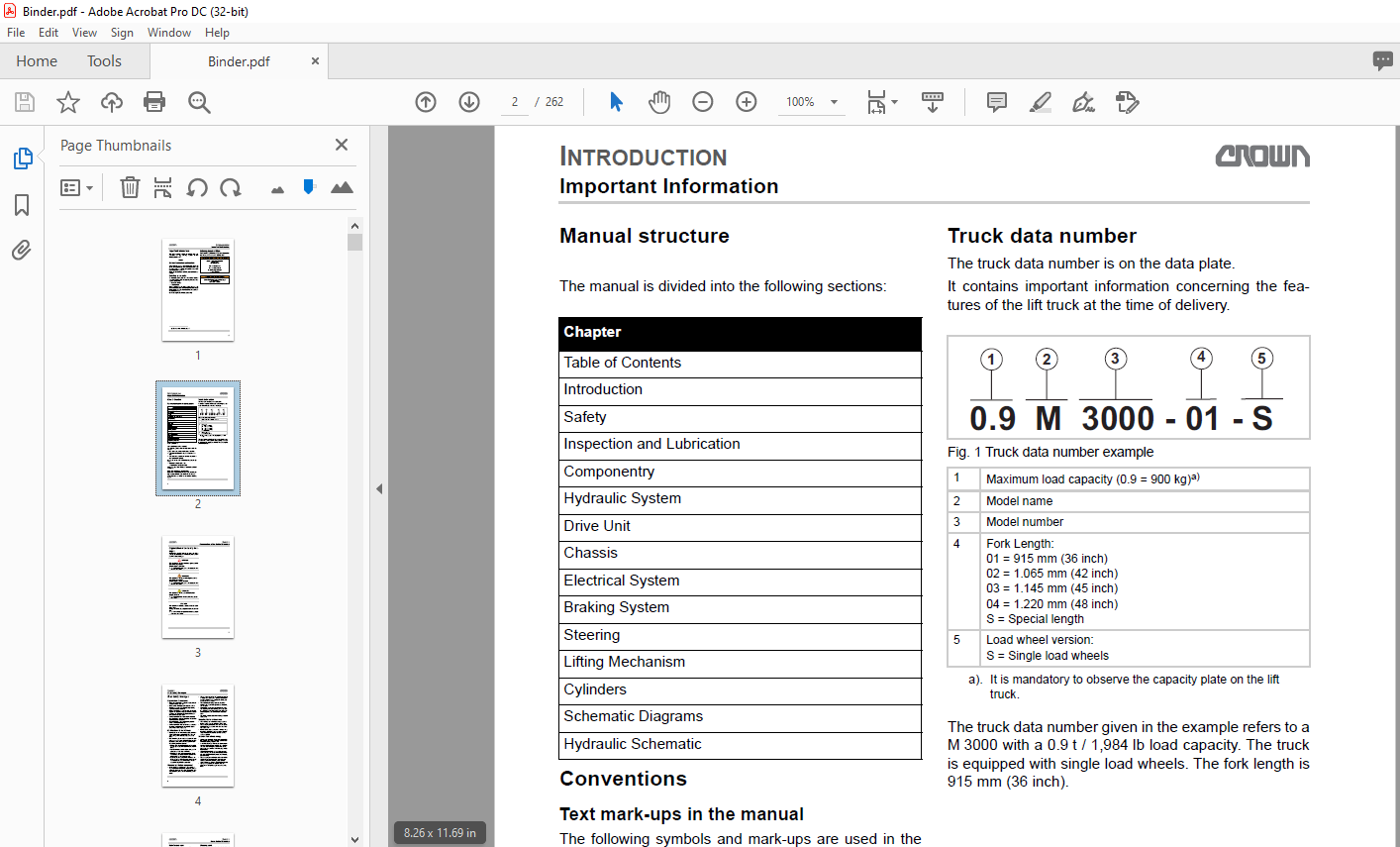
Truck data number 2
Safety 0
Organization of the Safety Messages 3
Basic Safety Messages 4
Organizational measures 4
Modifications to the lift truck 4
Personal protection equipment 4
Securing the hazardous area 4
Hazards from stored energy 4
Maintenance work 5
Restoring the lift truck to service after maintenance work 5
Cleaning work 5
Handling batteries 5
Warning and instruction decals 5
Lifting equipment and lifting accessories 6
Environmental protection 6
Safety Mechanisms and Protective Guards 7
Mast guard (standard) or mesh screen (optional) 7
Load backrest (optional) 7
Safety reverse switch 8
Battery disconnect (power disconnect) 8
Free-lift switch 8
Cleaning the Truck and Componentry 9
Effects of incorrect cleaning 9
Electrical components 9
Roller and slide bearings 9
Environmental protection 9
Cleaning the entire truck 9
Cleaning removed componentry 10
Cleaning other mechanical componentry 10
Storing and Returning the Truck to Service 11
Previous tasks 11
Returning the truck to service 11
Final tasks 11
Control of Hazardous Energy 12
(Lockout/Tagout) 12
Lockout/Tagout Procedures 12
Tagout Procedure 12
Lockout Procedure with the Battery Installed 13
Lockout Procedure Without the Battery Installed 13
Preparing the Lift Truck for Maintenance 13
Battery 14
Preparing the Battery for Removal 14
Removing the Batteries from the Lift Truck 14
Installing the Batteries in the Lift Truck 15
Maintenance free and wet cell 15
Final tasks 15
Discharge the Capacitor Voltage 15
The following procedure describes how to discharge the capacitors safely before performing maintenance near bus bars, power cables, or other electrical components on the lift truck 15
General Hot Work Instructions 16
Releasing the Hydraulic Pressure 16
Parking Brake 17
Releasing the Parking Brake 17
Towing the Lift Truck 20
Preparing for Towing the Lift Truck 20
Towing the Lift Truck in the Power Unit First Direction 20
Lifting and Blocking the Lift Truck 20
The following procedures describe how to lift and block the lift truck safely 20
Blocking the Inner Mast 23
Lifting the Lift Truck 23
Necessary equipment 23
Preparing for Lifting the Lift Truck 23
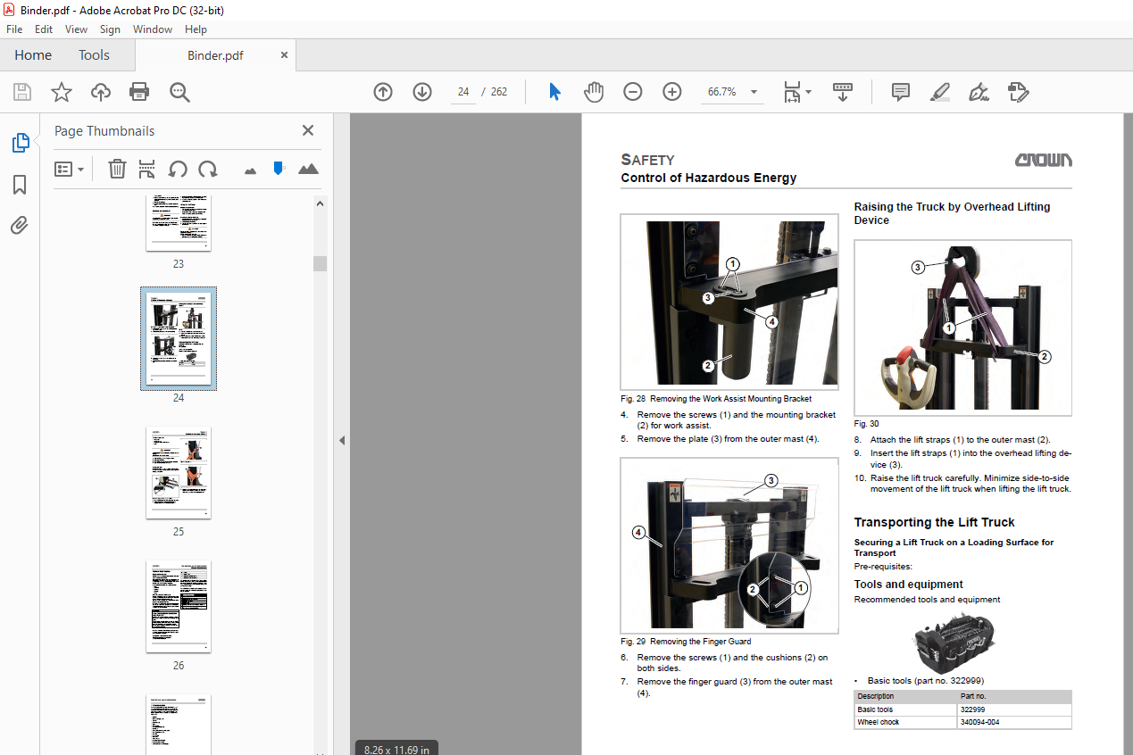
Raising the Truck by Overhead Lifting Device 24
Transporting the Lift Truck 24
Securing a Lift Truck on a Loading Surface for Transport 24
Tools and equipment 24
Additional equipment 25
Technican Tips 25
Inspection and Lubrication 0
Planned Maintenance 26
Maintenance schedule 26
Annual inspection in accordance with FEM 4004 26
Terms and abbreviations used 26
1 Visual Inspection 27
2 Functional test and test drive 28
3 Preparing the truck for maintenance 29
Take the truck out of service 29
Securing the work area and lift truck 29
Remove covers for maintenance 30
Removing the battery deck lid 30
Removing the left side cover 30
Removing the right side cover 31
Removing the motor compartment cover 31
Removing the knuckle cover 31
4 Maintenance schedule 33
5 Inspection with the lift truck jacked up 35
Jacking up the truck 35
Required tools: 35
Maintenance schedule (continued) 38
Lowering the truck 39
6 Clean and perform final test drive 42
Install knuckle cover 42
Install the motor compartment cover 42
Installing the right side cover 43
Installing the battery deck lid 43
Final tasks 43
Starting up the lift truck 43
Removing the lockout 44
Final test drive 45
Lubricants and Auxiliary Materials 46
Abbreviations 46
Standard Torque Values (Nm) 48
Standard Torque Values (in lb/ ft lb) 49
Componentry 0
Standard 50
“Soft lowering” option 51
Lift truck overview 52
Hydraulic System 0
Drift Test 54
Preconditions for drift tests 54
Perform the lift truck drift test 54
Hydraulic system troubleshooting 55
M 3000 Standard 56
Replacing the hydraulic pump motor 57
Previous tasks 57
Removing the hydraulic unit with reservoir 57
Removing the hydraulic pump 58
Removing the hydraulic pump motor 58
Installing the hydraulic pump motor 59
Installing the hydraulic pump 59
Installing the hydraulic unit with reservoir 60
Final tasks 61
Hydraulic oil change 62
Previous tasks 62
Removing the hydraulic unit with reservoir 62
Draining the hydraulic reservoir and replacing the filter 63
Filling the hydraulic reservoir 64
Installing the hydraulic unit with hydraulic reservoir 64
Final tasks 65
Replacing the hydraulic pump 66
Previous tasks 66
Removing the hydraulic unit with reservoir 66
Draining the hydraulic reservoir and replacing the hydraulic pump 67
Installing the hydraulic pump 68
Filling the hydraulic reservoir 69
Installing the hydraulic unit with reservoir 69
Final tasks 70
Replace the hydraulic pump receptacle 71
Previous tasks 71
Removing the hydraulic unit with reservoir 71
Removing the hydraulic pump 72
Removing the hydraulic pump motor 73
Replace the hydraulic pump receptacle 73
Installing the hydraulic pump motor 75
Installing the hydraulic pump 76
Installing the hydraulic unit with reservoir 77
Final tasks 77
Check the hydraulic reservoir level 78
Requirement: 78
Bleeding the hydraulic system 79
Check the hydraulic reservoir level 79
Flushing the hydraulic system 79
Bleeding the hydraulic system 79
M 3000 Option Soft Lowering 81
Replacing the hydraulic pump motor 83
Previous tasks 83
Removing the hydraulic pump motor 83
Installing the hydraulic pump motor 83
Final tasks 84
Replacing the carbon brushes of the hydraulic pump motor 85
Previous tasks 85
Removing the cover for the carbon brushes 85
Removing the carbon brushes 85
Checking the carbon brushes and the armature 86
Installing the carbon brush 86
Installing the cover for the carbon brushes 87
Final tasks 87
Hydraulic oil change 88
Previous tasks 88
Removing the hydraulic pump with reservoir 88
Draining the hydraulic reservoir and replacing the filter 89
Installing the hydraulic pump with reservoir 89
Final tasks 90
Replacing the hydraulic pump 91
Previous tasks 91
Previous tasks 91
Draining the hydraulic reservoir 91
Replacing the hydraulic pump 91
Final tasks 93
Calibrating Access 2 94
Requirement: 94
Check the hydraulic reservoir level 96
Requirement: 96
Bleeding the hydraulic system 97
Check the hydraulic reservoir level 97
Flushing the hydraulic system 97
Bleeding the hydraulic system 97
Drive Unit 0
Overview of the Drive Unit 99
Changing the gearbox oil100
Previous tasks100
Changing the gearbox oil100
Permissible oil types100
Final tasks100
Checking the oil level101
Previous tasks101
Adding the oil101
Permissible oil types101
Final tasks101
Removing and Installing the Traction Motor M1102
Previous tasks102
Removing the traction motor102
Installing the traction motor103
Final tasks104
Chassis 0
Replacing the Battery Deck Lid105
Previous tasks105
Removing the battery deck lid105
Installing the battery deck lid105
Final tasks105
Replacing Left Side Cover106
Previous tasks106
Removing the left side cover106
Installing the left side cover106
Final tasks106
Replacing Right Side Cover107
Previous tasks107
Removing the right side cover107
Installing the right side cover107
Final tasks107
Replace the Main Cover108
Previous tasks108
Remove the main cover108
Install the main cover108
Final tasks108
Replace Knuckle Cover109
Previous tasks109
Removing the knuckle cover109
Installing the knuckle cover109
Final tasks109
Replace the Center Cover110
Previous tasks110
Remove the center cover110
Install the center cover110
Final tasks111
Replacing the Drive Wheel112
Previous tasks112
Loosening the screws on the drive wheel112
Jacking up the Truck112
Required tools:113
Removing the drive wheel115
Installing the drive wheel115
Lowering the Truck116
Tightening the drive wheel117
Final tasks117
Replacing the Load Wheel118
Previous tasks118
Removing the load wheel118
Installing the load wheel118
Final tasks118
Replacing Caster Wheel119
Previous tasks119
Removing the caster wheel unit119
Removing the caster wheel119
Check damper sheet119
Assembling the caster wheel120
Checking the caster wheel unit bearing120
Installing the caster wheel unit120
Final tasks121
Removing/ Installing Caster Wheel Unit122
Previous tasks122
Removing the caster wheel unit122
Checking the caster wheel unit bearing122
Installing the caster wheel unit122
Final tasks123
Replacing Caster Wheel Bearing124
Previous tasks124
Removing the caster wheel unit124
Removing caster wheel bearing124
Replacing caster wheel bearing124
Installing caster wheel bearing125
Installing the caster wheel unit125
Final tasks125
Adjusting the Caster Wheels126
General126
Previous tasks126
Adjusting the caster wheels126
Final tasks128
Adjusting of Outrigger129
Previous tasks129
Final tasks130
Braking System 0
Componentry and Operation131
Service brake131
Parking brake131
Control Handle Positions132
Travel and brake zone description132
Upper brake zone (1)132
Brake override zone (2)132
Drive zone (3)132
Lower brake zone (4)132
Traveling in vertical tiller mode133
Traveling in vertical tiller mode133
Auto deactivation of vertical tiller function133
Traveling in the brake override zone134
Testing the Stopping Distance135
Requirements135
Performing the test135
Table of stopping distances135
Check the Parking Brake136
Inspecting the Parking Brake137
Previous tasks137
Manually releasing the parking brake137
Inspecting the parking brake137
Activating the parking brake137
Final tasks138
Manually Releasing the Parking Brake139
Component overview139
Releasing the parking brake139
Previous tasks139
Activating the parking brake139
Final tasks140
Replacing Parking Brake141
Component overview141
Previous tasks141
Removing the parking brake141
Replacing parking brake141
Installing the parking brake142
Final tasks142
Troubleshooting Barking Brake143
Steering 0
X10® Control Handle144
Assembly overview144
Opening the panels of the X10 control handle145
Previous tasks145
Removing the switch unit145
Removing the horn switch145
Removing the handles146
Removing the shells146
Installing the shells146
Installing the handles146
Horn switch assembly147
Installing the switch unit147
Final tasks148
Replacing the switch unit of the X10® control handle149
Previous tasks149
Removing the switch unit149
Installing the switch unit149
Final tasks150
Replace the rabbit/turtle switch on the X10® control handle (HSS)151
Previous tasks151
Removing the switch unit151
Removing the rabbit/turtle switch (HSS)151
Replacing the rabbit/turtle switch (HSS)151
Installing the rabbit/turtle switch (HSS)152
Installing the switch unit152
Final tasks152
Replacing the hydraulic printed circuit board of the X10® control handle (HYD PCB)153
Previous tasks153
Removing the switch unit153
Removing the hydraulic printed circuit board (HYD PCB)153
Replacing the hydraulic printed circuit board (HYD PCB)153
Installing the hydraulic printed circuit board (HYD PCB)154
Installing the switch unit154
Final tasks154
Replacing the hydraulic printed circuit board of the X10® control handle (MAIN PCB)155
Previous tasks155
Removing the switch unit155
Removing the main circuit board155
Removing the main printed circuit board (MAIN PCB)155
Installing the main printed circuit board (MAIN PCB)156
Installing the switch unit156
Final tasks156
Replacing the traction potentiometer of the X10® control handle (POT)157
Previous tasks157
Removing the switch unit157
Removing the thumb wheels157
Removing the cover158
Removing the traction potentiometer (POT)158
Replacing the traction potentiometer (POT)158
Cover assembly159
Installing the thumb wheels159
Installing the switch unit159
Final tasks160
Replacing the safety reverse switch of the X10® control handle (SAS)161
Previous tasks161
Removing the switch unit161
Removing the thumb wheels161
Removing the cover162
Removing the safety reverse switch (SAS)162
Safety reverse switch (SAS) assembly162
Cover assembly162
Installing the thumb wheels163
Installing the switch unit163
Final tasks163
Replacing the horn switch of the X10® control handle (HNS)164
Previous tasks164
Removing the switch unit164
Removing the horn switch164
Installing the switch unit165
Final tasks166
Replacing the handles of the X10® control handle167
Previous tasks167
Removing the switch unit167
Removing the horn switch167
Removing the handles168
Installing the handles168
Horn switch assembly168
Installing the switch unit169
Final tasks169
Lifting Mechanism 0
Maintaining the Lift Chain and Chain Anchors170
Adapting the maintenance intervals to the application conditions170
Periodic replacement of chain anchors and lift chains170
Disconnecting lift chains171
Required tools and equipment171
Disconnecting171
Lift Chain172
Checking the chain anchor and lift chain service hours172
Clean lift chain172
Lubricating the lift chain172
Checking the Lift Chains for Wear and Damage174
Checking the lift chain elongation174
Tools required174
Test preparation174
Checking the lift chain elongation with the wear gauge175
Checking the lift chain elongation with the steel ruler176
Checking the chain for other damage177
Removing and Installing the Lift Chain (For Cleaning)180
Previous tasks180
Lift chain removal180
Clean lift chain181
Tools and equipment181
Clean lift chain181
Lubricating and preserving the lift chain181
Installing the lift chain181
Final tasks182
Removing the block from the fork carriage182
Adjusting the height of the forks182
Replacing the Lift Chains183
Previous tasks183
Lift chain removal183
Lubricating and preserving the lift chain184
Installing the lift chain184
Final tasks185
Removing the block from the fork carriage185
Adjusting the height of the forks185
Fork187
Terms and identification187
Identification187
Checking the Fork188
Checking the fork blades for cracks188
Checking the fork mount and weld seams for cracks188
Check the fork tip for straightness188
Checking the blade for warping189
Measuring the fork tip width189
Checking the fork height difference189
Checking the fork stop189
Measuring the fork blade wear190
Tools and equipment190
Replacing Fork Blades191
Previous tasks191
Removing fork blades191
Installing fork blades191
Final tasks192
Replacing the Fork Stop193
Previous tasks193
Removing the fork stop193
Installing the fork stop193
Final tasks194
Cylinders 0
Lift Cylinder Removal and Installation195
Previous tasks195
Releasing the lift chain from the chain anchor and chain roller195
Removing the block from the fork carriage195
Blocking inner mast195
Removing the yoke196
Removing the chain anchor196
Removing the lift cylinder197
Installing the lift cylinder198
Installing the chain anchor198
Installing the yoke199
Remove the block from the inner mast200
Blocking the fork carriage200
Secure the lift chain in the chain roller and chain anchor200
Removing the block from the fork carriage201
Adjusting the height of the forks201
Final tasks201
Table of Contents 0
Introduction 0
Important Information 2
Service technician qualification 2
Ordering spare parts 2
Ordering documentation 2
Manual structure 3
Conventions 3
Text mark-ups in the manual 3
Brief description of equipment 3
Truck data number 3
Safety 0
Organization of the Safety Messages 2
Basic Safety Messages 3
Organizational measures 3
Modifications to the lift truck 3
Personal protection equipment 3
Securing the hazardous area 3
Hazards from stored energy 3
Maintenance work 4
Restoring the lift truck to service after maintenance work 4
Cleaning work 4
Handling batteries 4
Warning and instruction decals 4
Lifting equipment and lifting accessories 5
Environmental protection 5
Safety Mechanisms and Protective Guards 6
Mast guard (standard) or mesh screen (optional) 6
Load backrest (optional) 6
Safety reverse switch 7
Battery disconnect (power disconnect) 7
Free-lift switch 7
Cleaning the Truck and Componentry 8
Effects of incorrect cleaning 8
Electrical components 8
Roller and slide bearings 8
Environmental protection 8
Cleaning the entire truck 8
Cleaning removed componentry 9
Cleaning other mechanical componentry 9
Storing and Returning the Truck to Service 10
Previous tasks 10
Returning the truck to service 10
Final tasks 10
Control of Hazardous Energy 13
(Lockout/Tagout) 13
Lockout/Tagout Procedures 13
Tagout Procedure 13
Lockout Procedure with the Battery Installed 14
Lockout Procedure Without the Battery Installed 14
Preparing the Lift Truck for Maintenance 14
Battery 15
Preparing the Battery for Removal 15
Removing the Batteries from the Lift Truck 15
Installing the Batteries in the Lift Truck 16
Maintenance free and wet cell 16
Final tasks 16
Discharge the Capacitor Voltage 16
The following procedure describes how to discharge the capacitors safely before performing maintenance near bus bars, power cables, or other electrical components on the lift truck 16
General Hot Work Instructions 17
Releasing the Hydraulic Pressure 17
Parking Brake 18
Releasing the Parking Brake 18
Towing the Lift Truck 21
Preparing for Towing the Lift Truck 21
Towing the Lift Truck in the Power Unit First Direction 21
Lifting and Blocking the Lift Truck 21
The following procedures describe how to lift and block the lift truck safely 21
Blocking the Inner Mast 24
Lifting the Lift Truck 24
Necessary equipment 24
Preparing for Lifting the Lift Truck 24
Raising the Truck by Overhead Lifting Device 25
Transporting the Lift Truck 25
Securing a Lift Truck on a Loading Surface for Transport 25
Tools and equipment 25
Additional equipment 26
Technican Tips 26
Inspection and Lubrication 0
Planned Maintenance 2
Maintenance schedule 2
Annual inspection in accordance with FEM 4004 2
Terms and abbreviations used 2
1 Visual Inspection 4
2 Functional test and test drive 5
3 Preparing the truck for maintenance 6
Take the truck out of service 6
Securing the work area and lift truck 6
Remove covers for maintenance 7
Removing the battery deck lid 7
Removing the left side cover 7
Removing the right side cover 8
Removing the motor compartment cover 8
Removing the knuckle cover 8
4 Maintenance schedule 10
5 Inspection with the lift truck jacked up 12
Jacking up the truck 12
Required tools: 12
Maintenance schedule (continued) 15
Lowering the truck 16
6 Clean and perform final test drive 19
Install knuckle cover 19
Install the motor compartment cover 19
Installing the right side cover 20
Installing the battery deck lid 20
Final tasks 20
Starting up the lift truck 20
Removing the lockout 21
Final test drive 22
Lubricants and Auxiliary Materials 23
Abbreviations 23
Standard Torque Values (Nm) 25
Standard Torque Values (in lb/ ft lb) 26
Componentry 0
Standard 2
“Soft lowering” option 3
Lift truck overview 4
Hydraulic System 0
Drift Test 2
Preconditions for drift tests 2
Perform the lift truck drift test 2
Hydraulic system troubleshooting 3
M 3000 Standard 4
Replacing the hydraulic pump motor 5
Previous tasks 5
Removing the hydraulic unit with reservoir 5
Removing the hydraulic pump 6
Removing the hydraulic pump motor 6
Installing the hydraulic pump motor 7
Installing the hydraulic pump 7
Installing the hydraulic unit with reservoir 8
Final tasks 9
Hydraulic oil change 10
Previous tasks 10
Removing the hydraulic unit with reservoir 10
Draining the hydraulic reservoir and replacing the filter 11
Filling the hydraulic reservoir 12
Installing the hydraulic unit with hydraulic reservoir 12
Final tasks 13
Replacing the hydraulic pump 14
Previous tasks 14
Removing the hydraulic unit with reservoir 14
Draining the hydraulic reservoir and replacing the hydraulic pump 15
Installing the hydraulic pump 16
Filling the hydraulic reservoir 17
Installing the hydraulic unit with reservoir 17
Final tasks 18
Replace the hydraulic pump receptacle 19
Previous tasks 19
Removing the hydraulic unit with reservoir 19
Removing the hydraulic pump 20
Removing the hydraulic pump motor 21
Replace the hydraulic pump receptacle 21
Installing the hydraulic pump motor 23
Installing the hydraulic pump 24
Installing the hydraulic unit with reservoir 25
Final tasks 25
Check the hydraulic reservoir level 26
Requirement: 26
Bleeding the hydraulic system 27
Check the hydraulic reservoir level 27
Flushing the hydraulic system 27
Bleeding the hydraulic system 27
M 3000 Option Soft Lowering 29
Replacing the hydraulic pump motor 31
Previous tasks 31
Removing the hydraulic pump motor 31
Installing the hydraulic pump motor 31
Final tasks 32
Replacing the carbon brushes of the hydraulic pump motor 33
Previous tasks 33
Removing the cover for the carbon brushes 33
Removing the carbon brushes 33
Checking the carbon brushes and the armature 34
Installing the carbon brush 34
Installing the cover for the carbon brushes 35
Final tasks 35
Hydraulic oil change 36
Previous tasks 36
Removing the hydraulic pump with reservoir 36
Draining the hydraulic reservoir and replacing the filter 37
Installing the hydraulic pump with reservoir 37
Final tasks 38
Replacing the hydraulic pump 39
Previous tasks 39
Previous tasks 39
Draining the hydraulic reservoir 39
Replacing the hydraulic pump 39
Final tasks 41
Calibrating Access 2 42
Requirement: 42
Check the hydraulic reservoir level 44
Requirement: 44
Bleeding the hydraulic system 45
Check the hydraulic reservoir level 45
Flushing the hydraulic system 45
Bleeding the hydraulic system 45
Drive Unit 0
Overview of the Drive Unit 2
Changing the gearbox oil 3
Previous tasks 3
Changing the gearbox oil 3
Permissible oil types 3
Final tasks 3
Checking the oil level 4
Previous tasks 4
Adding the oil 4
Permissible oil types 4
Final tasks 4
Removing and Installing the Traction Motor M1 6
Previous tasks 6
Removing the traction motor 6
Installing the traction motor 7
Final tasks 8
Chassis 0
Replacing the Battery Deck Lid 2
Previous tasks 2
Removing the battery deck lid 2
Installing the battery deck lid 2
Final tasks 2
Replacing Left Side Cover 3
Previous tasks 3
Removing the left side cover 3
Installing the left side cover 3
Final tasks 3
Replacing Right Side Cover 4
Previous tasks 4
Removing the right side cover 4
Installing the right side cover 4
Final tasks 4
Replace the Main Cover 5
Previous tasks 5
Remove the main cover 5
Install the main cover 5
Final tasks 5
Replace Knuckle Cover 7
Previous tasks 7
Removing the knuckle cover 7
Installing the knuckle cover 7
Final tasks 7
Replace the Center Cover 8
Previous tasks 8
Remove the center cover 8
Install the center cover 8
Final tasks 9
Replacing the Drive Wheel 10
Previous tasks 10
Loosening the screws on the drive wheel 10
Jacking up the Truck 10
Required tools: 11
Removing the drive wheel 13
Installing the drive wheel 13
Lowering the Truck 14
Tightening the drive wheel 15
Final tasks 15
Replacing the Load Wheel 17
Previous tasks 17
Removing the load wheel 17
Installing the load wheel 17
Final tasks 17
Replacing Caster Wheel 18
Previous tasks 18
Removing the caster wheel unit 18
Removing the caster wheel 18
Check damper sheet 18
Assembling the caster wheel 19
Checking the caster wheel unit bearing 19
Installing the caster wheel unit 19
Final tasks 20
Removing/ Installing Caster Wheel Unit 21
Previous tasks 21
Removing the caster wheel unit 21
Checking the caster wheel unit bearing 21
Installing the caster wheel unit 21
Final tasks 22
Replacing Caster Wheel Bearing 23
Previous tasks 23
Removing the caster wheel unit 23
Removing caster wheel bearing 23
Replacing caster wheel bearing 23
Installing caster wheel bearing 24
Installing the caster wheel unit 24
Final tasks 24
Adjusting the Caster Wheels 25
General 25
Previous tasks 25
Adjusting the caster wheels 25
Final tasks 27
Adjusting of Outrigger 28
Previous tasks 28
Final tasks 29
Electrical System 0
Replacing Access 3 2
Previous tasks 2
Removing Access 3 2
Installing Access 3 3
Final tasks 5
Status LED 6
Connecting the Programming Device to the Vehicle 7
General 7
Connecting the Controller Handset to the Lift Truck 8
Previous tasks 8
Final tasks 8
Operating Access 3 Menu 9
Menu structure 9
Menu functions 11
Functions Menu, general 11
Parameter change Menu 12
Settings and Alarms 13
Tester menu 14
TESTER menu 15
Alarms Menu 16
ALARMS Menu 17
PROGRAM V ACC Menu 19
Preparatory measures 19
Calibration 19
Config Menu 17
CONFIG Menu 17
SET MODEL 23
SET OPTIONS 17
ADJUSTMENTS 23
Menu functions 10
Parameter change 10
TESTER 10
ALARMS 10
PROGRAM VACC 10
CONFIG 10
Traction Control Module Safety Test (PMT Test) 24
Previous tasks 24
Final tasks 25
Battery Discharge Indicator (BDI) 27
Operation 27
General 27
Battery discharge indicator setting (BDI) 28
Calibration for wet batteries 28
Troubleshooting 29
Replacing the Battery Discharge Indicator (BDI) 30
Previous tasks 30
Loosen the mounting bracket of the battery discharge indicator 30
Removing the battery discharge indicator 30
Installing the battery discharge indicator 30
Attach the mounting bracket of battery discharge indicator 31
Final tasks 31
Replacing the Batteries 32
Previous tasks 32
Removing the batteries from the lift truck 32
Installing the batteries in the lift truck 32
(Maintenance free) 32
Final tasks 33
General DC Motor Maintenance Instructions 34
Carbon brushes 34
Rotor 34
Armature 34
Installing and Removing the Hydraulic Pump Contactor 35
Previous tasks 35
Removing the hydraulic pump contactor 35
Installing the hydraulic pump contactor 36
Final tasks 36
Repairing the Contactor 37
Dismantling the contactor 37
Checking contacts and springs 37
Checking the coil 38
Reassembling the contactor 38
On-board Charger 39
Assembly location 39
standard 39
“Soft Lowering” option 39
Functional monitoring 39
Display status of the yellow and green LEDs 39
General 40
Setting the charge curves 40
Battery charging phases 40
First phase (I1) 40
Second phase (P) 40
Third phase (U) 40
Fourth phase (I2) 40
End of normal charging 40
Special charging phases 40
Equalization charge 40
Float charge 41
Partial charging 41
Charging errors 42
Green LED not lit 42
Green LED flashing 42
Important technical data 42
Replacing the On-Board Battery Charger 43
Previous tasks 43
Loosen the mounting bracket of the battery discharge indicator 43
Removing the mounting bracket 43
Removing the on-board battery charger 44
Installing the on-board battery charger 46
Installing the mounting bracket 48
Attach the mounting bracket of battery discharge indicator 48
Final tasks 49
Replacing the On-Board Charger Cable 50
Previous tasks 50
Loosening the mounting bracket of the battery discharge indicator 50
Disconnecting charger cable 50
Connecting charger cable 50
Attach the mounting bracket of battery discharge indicator 51
Final tasks 51
Braking System 0
Componentry and Operation 2
Service brake 2
Parking brake 2
Control Handle Positions 3
Travel and brake zone description 3
Upper brake zone (1) 3
Brake override zone (2) 3
Drive zone (3) 3
Lower brake zone (4) 3
Traveling in vertical tiller mode 4
Traveling in vertical tiller mode 4
Auto deactivation of vertical tiller function 4
Traveling in the brake override zone 5
Testing the Stopping Distance 6
Requirements 6
Performing the test 6
Table of stopping distances 6
Check the Parking Brake 7
Inspecting the Parking Brake 8
Previous tasks 8
Manually releasing the parking brake 8
Inspecting the parking brake 8
Activating the parking brake 8
Final tasks 9
Manually Releasing the Parking Brake 10
Component overview 10
Releasing the parking brake 10
Previous tasks 10
Activating the parking brake 10
Final tasks 11
Replacing Parking Brake 12
Component overview 12
Previous tasks 12
Removing the parking brake 12
Replacing parking brake 12
Installing the parking brake 13
Final tasks 13
Troubleshooting Barking Brake 14
Steering 0
X10® Control Handle 2
Assembly overview 2
Opening the panels of the X10 control handle 3
Previous tasks 3
Removing the switch unit 3
Removing the horn switch 3
Removing the handles 4
Removing the shells 4
Installing the shells 4
Installing the handles 4
Horn switch assembly 5
Installing the switch unit 5
Final tasks 6
Replacing the switch unit of the X10® control handle 7
Previous tasks 7
Removing the switch unit 7
Installing the switch unit 7
Final tasks 8
Replace the rabbit/turtle switch on the X10® control handle (HSS) 9
Previous tasks 9
Removing the switch unit 9
Removing the rabbit/turtle switch (HSS) 9
Replacing the rabbit/turtle switch (HSS) 9
Installing the rabbit/turtle switch (HSS) 10
Installing the switch unit 10
Final tasks 10
Replacing the hydraulic printed circuit board of the X10® control handle (HYD PCB) 11
Previous tasks 11
Removing the switch unit 11
Removing the hydraulic printed circuit board (HYD PCB) 11
Replacing the hydraulic printed circuit board (HYD PCB) 11
Installing the hydraulic printed circuit board (HYD PCB) 12
Installing the switch unit 12
Final tasks 12
Replacing the hydraulic printed circuit board of the X10® control handle (MAIN PCB) 13
Previous tasks 13
Removing the switch unit 13
Removing the main circuit board 13
Removing the main printed circuit board (MAIN PCB) 13
Installing the main printed circuit board (MAIN PCB) 14
Installing the switch unit 14
Final tasks 14
Replacing the traction potentiometer of the X10® control handle (POT) 16
Previous tasks 16
Removing the switch unit 16
Removing the thumb wheels 16
Removing the cover 17
Removing the traction potentiometer (POT) 17
Replacing the traction potentiometer (POT) 17
Cover assembly 18
Installing the thumb wheels 18
Installing the switch unit 18
Final tasks 19
Replacing the safety reverse switch of the X10® control handle (SAS) 20
Previous tasks 20
Removing the switch unit 20
Removing the thumb wheels 20
Removing the cover 21
Removing the safety reverse switch (SAS) 21
Safety reverse switch (SAS) assembly 21
Cover assembly 21
Installing the thumb wheels 22
Installing the switch unit 22
Final tasks 22
Replacing the horn switch of the X10® control handle (HNS) 23
Previous tasks 23
Removing the switch unit 23
Removing the horn switch 23
Installing the switch unit 24
Final tasks 25
Replacing the handles of the X10® control handle 26
Previous tasks 26
Removing the switch unit 26
Removing the horn switch 26
Removing the handles 27
Installing the handles 27
Horn switch assembly 27
Installing the switch unit 28
Final tasks 28
Lifting Mechanism 0
Maintaining the Lift Chain and Chain Anchors 2
Adapting the maintenance intervals to the application conditions 2
Periodic replacement of chain anchors and lift chains 2
Disconnecting lift chains 3
Required tools and equipment 3
Disconnecting 3
Lift Chain 4
Checking the chain anchor and lift chain service hours 4
Clean lift chain 4
Lubricating the lift chain 4
Checking the Lift Chains for Wear and Damage 6
Checking the lift chain elongation 6
Tools required 6
Test preparation 6
Checking the lift chain elongation with the wear gauge 7
Checking the lift chain elongation with the steel ruler 8
Checking the chain for other damage 9
Removing and Installing the Lift Chain (For Cleaning) 12
Previous tasks 12
Lift chain removal 12
Clean lift chain 13
Tools and equipment 13
Clean lift chain 13
Lubricating and preserving the lift chain 13
Installing the lift chain 13
Final tasks 14
Removing the block from the fork carriage 14
Adjusting the height of the forks 14
Replacing the Lift Chains 15
Previous tasks 15
Lift chain removal 15
Lubricating and preserving the lift chain 16
Installing the lift chain 16
Final tasks 17
Removing the block from the fork carriage 17
Adjusting the height of the forks 17
Fork 19
Terms and identification 19
Identification 19
Checking the Fork 20
Checking the fork blades for cracks 20
Checking the fork mount and weld seams for cracks 20
Check the fork tip for straightness 20
Checking the blade for warping 21
Measuring the fork tip width 21
Checking the fork height difference 21
Checking the fork stop 21
Measuring the fork blade wear 22
Tools and equipment 22
Replacing Fork Blades 23
Previous tasks 23
Removing fork blades 23
Installing fork blades 23
Final tasks 24
Replacing the Fork Stop 25
Previous tasks 25
Removing the fork stop 25
Installing the fork stop 25
Final tasks 26
Cylinders 0
Lift Cylinder Removal and Installation 2
Previous tasks 2
Releasing the lift chain from the chain anchor and chain roller 2
Removing the block from the fork carriage 2
Blocking inner mast 2
Removing the yoke 3
Removing the chain anchor 3
Removing the lift cylinder 4
Installing the lift cylinder 5
Installing the chain anchor 5
Installing the yoke 6
Remove the block from the inner mast 7
Blocking the fork carriage 7
Secure the lift chain in the chain roller and chain anchor 7
Removing the block from the fork carriage 8
Adjusting the height of the forks 8
Final tasks 8
Schematic Diagrams 0
Electrical diagram for the standard 2
Traction control module 3
Traction control module 4
Power unit control module 5
X10® control handle control module 5
Hydraulic Schematic 0
Hydraulic symbols 2
M 3000 standard 6
“Soft lowering” M 3000 option 7
Schematic Diagrams 0
Electrical diagram for the standard252
Traction control module253
Traction control module254
Power unit control module255
X10® control handle control module255
Hydraulic Schematic 0
Hydraulic symbols257
M 3000 standard261
“Soft lowering” M 3000 option262
IMAGES PREVIEW OF THE MANUAL:
More products