$38
Crown Forklift MPC 3000 Pallet Service Manual – PDF DOWNLOAD
Crown Forklift MPC 3000 Pallet Service Manual – PDF DOWNLOAD
FILE DETAILS:
Crown Forklift MPC 3000 Pallet Service Manual – PDF DOWNLOAD
Language : English
Pages :493
Downloadable : Yes
File Type : PDF
TABLE OF CONTENTS:
Crown Forklift MPC 3000 Pallet Service Manual – PDF DOWNLOAD
Introduction 0
Service technician qualifications 1
Ordering replacement parts 1
Ordering documentation 1
Manual structure 2
Conventions 2
Text mark-ups in the manual 2
Brief description of equipment 2
Safety 0
Organizational measures 5
Modifications to the lift truck 5
Personal protection equipment 5
Securing hazardous areas 5
Hazards posed by stored energy 5
Maintenance work 6
Restoring the lift truck to service after maintenance work 6
Cleaning work 6
Handling batteries 6
Warning and instruction decals on the lift truck 6
Lifting equipment and lifting accessories 7
Environmental protection 7
Mast guard (standard) 8
Load backrest (optional) 8
Load overhead guard (standard) 9
Brake switch (standard) 9
Battery disconnect, power disconnect (standard) 9
Platform detection (standard) 9
Free-lift switch (standard) 10
Travel Assist (option) 10
Lifting the lift truck 11
Securing a truck with a TL or TF mast 12
Securing a truck with an NT mast 13
Securing the work area and lift truck 15
Previous tasks 17
Discharging the capacitor voltage 17
Required tools: 19
Lowering the truck 22
Removing the Lockout 24
Final test drive 25
Inspection and Lubrication 0
Effects of incorrect cleaning 26
Electrical componentry 26
Roller and slide bearings 26
Corrosion-protected surfaces 26
Environmental protection 26
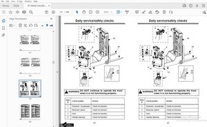
Cleaning the entire truck 27
Cleaning removed componentry 28
Cleaning other mechanical componentry 28
Maintenance schedule 30
Annual inspection in accordance with FEM 4004 30
Terms and abbreviations 30
General 31
Covers 32
Hydraulic system 33
Drive unit 34
Electrical system 35
Braking system 36
Steering 37
Lifting mechanism 37
Cylinders 39
Platform 39
Miscellaneous 40
Cold store truck requirements 41
Used abbreviations 41
Standard Torque Values (Nm) 45
Standard Torque Values (in lb/ ft lb) 46
Componentry 0
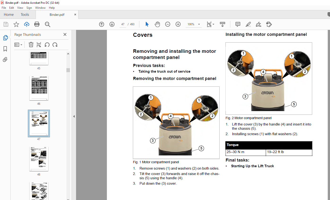
Removing and installing the motor compartment panel 47
Previous tasks: 47
Removing the motor compartment panel 47
Installing the motor compartment panel 47
Final tasks: 47
Removing and installing the bumper 48
Previous tasks: 48
Removing the bumper 48
Practical tip: 48
Installing the bumper 49
Final tasks 49
Removing and installing the lower battery cover panel (before 08/2020) 49
Removing and installing the lower battery cover panel (after 09/2020) 50
Previous tasks: 50
Removing the cover 50
Installing the cover 50
Previous tasks: 50
Removing and Installing the backrest 50
Previous tasks: 50
Removing the backrest 50
Installing the Backrest 51
Final tasks: 52
Removing and installing the cover with the storage compartment 52
Previous tasks: 52
Removing the cover with the storage compartment 52
Installing the cover with the storage compartment 52
Final tasks: 53
Replacing seat pad 53
Previous tasks: 53
Removing the seat pad 53
Installing the seat pad 53
Final tasks: 53
Previous tasks 54
Remove the overhead guard 54
Attaching the overhead guard 56
Practical tip: 56
Final tasks 58
HN 60
ALM 60
ECR1 62
ECR2, ECR3 62
M1 64
M3 64
POT 66
K1 67
BLS 68
SAS/BRS 68
FS (PF) 68
RS (FF) 68
HNS1 69
HNS2 69
HSS 69
KYS 69
LOS1 70
HPCS1, HPCS2 70
HPCS3, HPCS4 70
RAS 71
LINE 73
FPS1 74
FPS2 74
SAHS 74
TS1 75
TS2 75
STEER SENSOR 75
FU1 77
FU2 77
FU3 77
FU4 77
FU7 78
FU8 78
Access 1 80
Access 2/3 80
Access 5 80
Access 81 80
Access 82 81
BRK 83
FAN 83
DC-DC CONVERTER 83
KEYPAD 83
Electrical Componentry 88
Overview 88
Motor compartment 89
Motor compartment (continued) 90
Motor compartment (continued) 91
Platform 92
Battery compartment 92
Battery cover (515 mm wide) 93
Battery cover (440 mm wide) 94
Access 82 95
Electrical Componentry 96
Access 2/3 and Access 5 96
Line contactor 97
Motors M1-M3 98
Connectors in the motor compartment 99
Hydraulic valves and load sensor connectors100
Hydraulic System 0
TF mast105
Requirement:106
Previous tasks107
Removing the Hydraulic Unit with Reservoir107
Draining the Hydraulic Reservoir and Replacing the Filter108
Filling the Hydraulic Reservoir109
Installing the Hydraulic Unit with Hydraulic Reservoir109
Final tasks110
Previous tasks111
Removing the hydraulic unit with reservoir111
Replacing the hydraulic pump112
Filling the Hydraulic Reservoir115
Installing the hydraulic unit with hydraulic reservoir115
Final tasks116
Check the hydraulic reservoir level117
Flushing the Hydraulic System117
Venting the hydraulic circuit117
Replacing the relief valve119
Testing the relief valve119
Adjusting the relief valve119
Preparing the drift test120
Performing a drift test120
Drive Unit 0
Special tools required122
Removal122
Installation122
Change interval123
Permissible oil types123
Previous tasks123
Draining the oil123
Adding the oil124
Final tasks124
Previous tasks125
Required tools:125
Jacking up the truck126
Removing the drive wheel128
Installing the drive wheel128
Lowering the Truck129
Final tasks130
Previous tasks131
Replacing the gearbox pinion131
Replacing the rotor132
Final tasks136
Electrical System 0
Select service preset 2137
Select service preset 3137
Retrieve vehicle code138
Retrieve individual modules138
Pairing Menu140
Operator Menu141
Operator Menu142
Analyzer Menu A1–A2143
Analyzer Menu A3 Outputs and A4 Test Outputs144
Calibration Menu C1–C2145
Calibration Menu C3–C5146
Analyzer Menu Access 2 Inputs147
Analyzer Menu Access 3 Inputs148
Analyzer Menu Access 5 Inputs149
Features Menu F1–F4150
Features Menu F5–F14151
Features Menu F14–F19152
Features Menu F71–F74153
Hour Menu H1–H5154
Events Menu E1–E5155
Performance Menu P1–P3156
Performance Menu P4–P99157
Utilities Menu U1158
Utilities Menu U2159
Analyzer Menu A210160
Battery not latched161
Platform error161
Truck stopped163
Traction control module hot164
Traction motor hot166
Travel switch applied too soon167
Steer control module hot168
Steer motor hot170
Malfunctions with display of event code171
Locating malfunctions171
Event code groups171
Checking event codes171
Event code 100172
Event code 148173
Event Code – Group 200174
Event code 200174
Event code 201174
Event code 202175
Event code 203177
Event code 204177
Event code 205179
Event code 206180
Event code 207182
Event code 208183
Event code 209 to 215184
Event code 217184
Event code 218185
Event code 219186
Event code 220186
Event code 221187
Event code 223187
Event code 224188
Event code 225190
Event code 226190
Event code 228191
Event code 229192
Event code 230194
Event code 300196
Event code 301196
Event code 302197
Event code 303197
Event code 304198
Event code 305199
Event code 306200
Event code 307201
Event code 308201
Event code 309202
Event code 310203
Event code 314203
Event code 315204
Event code 316205
Event code 317205
Event code 319207
Event code 320209
Event code 321210
Event code 322211
Event code 324211
Event code 325212
Event code 326213
Event code 328214
Event code 329214
Event code 332214
Event code 333215
Event code 334215
Event code 335216
Event code 337217
Event code 338217
Event code 340218
Event code 341219
Event code 342219
Event code 343221
Event code 344222
Event code 345223
Event code 346224
Event code 347224
Event code 348225
Event code 500226
Event code 501226
Event code 502227
Event code 503227
Event code 504227
Event code 505227
Event code 506228
Event code 508228
Event code 509229
Event code 510230
Event code 511232
Event code 512232
Event code 513232
Event code 514233
Event code 515234
Event code 516234
Event code 517235
Event code 518237
Event code 519237
Event code 520238
Event code 522238
Event code 523238
Event code 524240
Event code 525240
Event code 526241
Event code 527242
Event code 528243
Event code 529243
Event code 530243
Event code 532245
Event code 535246
Event code 536247
Event code 537247
Event code 538247
Event code 539249
Event code 540250
Event code 541250
Event code 542251
Event code 543252
Event code 544252
Event code 545253
Event code 800254
Event code 801255
Event code 803256
Event code 804256
Event code 805256
Event code 806257
Event code 807257
Event code 808258
Event code 812258
Event code 813259
Event code 816259
Event code 817259
Event code 821260
Event code 822260
Event code 823261
Event code 824261
Event code 825262
Event code 826262
Event code 827263
Event code 832263
Event code 833264
Event code 834265
Event code 835265
Event code 836 and 837265
Event code 838265
Event code 839266
Event codes 840, 841 and 842266
Event code 844267
Event codes 845 and 846267
Event code 847268
Event code 900 to 905270
Event code 1000271
Event code 1001 or 1002272
Activating or deactivating performance settings276
Adjusting performance settings276
Calibrating the steering center position281
Calibrating the drive wheel for forward travel281
Calibrating the right steering lock282
Calibrating the left steering lock283
Saving and activating the settings283
Description of functionality286
Carry out test286
Requirements286
Check basic functions of the QPR system286
Check safety functions of the lift truck287
Check safety functions of the point laser287
Required tools287
Check safety function of the scanning laser288
Requirements291
Required tools291
Preparing the lift truck291
Setting the point lasers291
Setting the scanning laser292
Brushes293
Rotor293
Commutator:293
Previous tasks294
Removing the engine control unit for Infolink294
Removing the parking brake294
Removing the traction motor295
Installing the traction motor296
Installing the parking brake298
Installing the engine control unit for Infolink299
Final tasks299
Removing the control module301
Installing the control module301
Parameter setting302
Mechanical conversion303
Changing the software303
Mechanical conversion304
Changing the software304
Charging batteries305
Lithium-ion battery305
Charging a lithium-ion battery305
Lead acid battery305
Maintaining lead acid batteries305
Replacing a lead acid battery305
Required tools306
Removing the battery from the lift truck306
Installing the batteries in the truck309
Load profile and discharge curve311
Assigning a load profile311
Previous tasks312
Removing the contactor312
Installing the contactor313
Final tasks315
Dismantling the contactor316
Checking contacts and springs316
Checking the coil317
Reassembling the contactor317
Previous tasks318
Removing Access 2/3318
Installing Access 2/3321
Final tasks323
Previous tasks324
Removing Access 5324
Installing Access 5326
Final tasks329
Required tools330
Preparing the truck for the test330
Check Access 2330
Testing Access 3331
Check phase U331
Requirements331
Testing phase V331
Requirements331
Testing phase W331
Requirements331
Complete the PMT test on Access 2/3332
Testing Access 5332
Check phase U332
Requirements332
Testing phase V332
Requirements332
Testing phase W332
Requirements332
Complete the PMT test on Access 5333
Braking System 0
Service brake335
Parking brake335
Checking the air gap336
Troubleshooting336
Removing the parking brake337
Installing the parking brake337
Requirements339
Performing the test339
Required tools339
Table of stopping distances339
(Parking brake has been removed)340
Dismantling the Parking Brake340
Assembling the parking brake342
Steering 0
Steering Assembly343
Steering assembly componentry344
Removing the steering assembly344
Installing the steering assembly344
Final tasks344
Preparations345
Dismantling345
Assembly345
Final tasks346
Removing the control handle347
Installing the control handle347
Removing the return spring348
Installing the return spring348
Removing the steer sensor350
Installing the steer sensor350
Removing the X10® Control Handle352
Installing the X10® Control Handle353
Repairing the X10® Handle355
Replacing the X10 Handle shells356
Removing the shells356
Installing the Shells357
Replacing the switch unit358
Removing the switch unit358
Installing the switch unit358
Replacing the rabbit/turtle switch (HSS)359
Removing the rabbit/turtle switch359
Installing the rabbit/turtle switch359
Replacing the printed circuit boards of the X10 Control Handle360
Removing the hydraulic printed circuit board (HYD PCB)360
Installing the hydraulic printed circuit board360
Removing the main printed circuit board (MAIN PCB)360
Installing the main printed circuit board361
Replacing the traction potentiometer (POT)361
Removing the Traction Potentiometer361
Installing the traction potentiometer (POT)363
Replacing the brake switch (BRS)363
Removing the brake switch (BRS)363
Installing the BRS Switch364
Replacing the grips and horn switch (HNS)364
Previous tasks394
Removing SAHS394
Dismantling the SAHS assembly395
Installing and setting up the SAHS assembly395
Assemble SAHS396
Checking the operation of the SAHS396
Final tasks397
Removing the cable of the X10® Control Handle398
Installing the cable of the X10® Control Handle399
Final tasks401
Removing the cable of the X10® Control Handle402
Previous tasks402
Replacing the cable of the X10® Control Handle404
Installing the cable of the X10® Control Handle404
Final tasks406
Replacing the X10® Control Handle return springs407
Previous tasks407
Checking the bearings of the X10® Control Handle409
Disassembling the X10 Control Handle409
Installing the X10® Control Handle return springs410
Final tasks412
Removing the steer sensor of the X10® Control Handle413
Installing the steer sensor of the X10® Control Handle413
Lifting Mechanism 0
General415
Torques415
Removing the fork carriage418
Replacing the rollers418
Installing the fork carriage419
Checking and adjusting the fork height419
Removing the fork carriage422
Replacing the rollers422
Installing the fork carriage423
Checking and adjusting the fork height423
Removing the fork carriage426
Replacing the rollers426
Installing the fork carriage427
Checking and adjusting the fork height427
Preparations428
Replacing the rollers428
Adapting the maintenance intervals to the application conditions429
Periodic replacement of chain anchors and lift chains429
Scope of service work430
Checking the service hours for the lift chains and chain anchors430
Cleaning the lift chain430
Lubricating and preserving lift chains431
Checking the lift chain elongation432
Required tools432
Test preparation432
Checking the lift chain elongation with the wear gauge433
Checking the lift chain elongation with the steel ruler434
Checking the chain for other damage435
Requirements438
Preparing the plumb bob test438
Performing the plumb bob test438
Required Tools and Equipment439
Detachment439
Previous tasks440
Removing the lift chains440
Lubricating and Preserving the Lift Chain442
Installing the lift chain442
Removing the Block from the Fork Carriage444
Adjusting the Fork Height444
Final tasks444
Previous tasks445
Removing fork blades445
Installing fork blades446
Final tasks446
Terms and identification447
Terms447
Identification447
Checking the fork blades for cracks448
Checking the fork tip for straightness448
Checking the blade for warping449
Measuring the fork tip width449
Checking the fork height difference450
Checking the fork stop450
Measuring the fork blade wear450
Cylinders 0
Small Hook451
Extractor451
Producing extractors451
Groove aligning arbor for small rod packings451
Assembly devices for large rod packings452
Protective mechanisms452
Removing a large rod packing453
Removing a small rod packing453
Inserting a large rod packing453
Fitting a small rod packing454
Rod packing assembly, sealing lip first454
Removing the lift cylinder from the TL mast456
Assembling the lift cylinder on the TL mast456
Removing the lift cylinders from the TF mast458
Assembling the lift cylinder on the TF mast458
Free lift cylinder removal460
Free lift cylinder assembly461
Repairing the Lift Cylinder for the TL Mast463
Repairing the left lift cylinder465
Repairing the right lift cylinder468
Schematic Diagrams 0
QuickPick Remote®483
CAN Bus484
Lithium-Ion Battery Preparation Option485
With key switch485
With keypad485
Hydraulic Schematic 0
MPC 3000 Series with NT mast491
MPC 3000 Series with TL mast492
MPC 3000 Series with TF mast493
IMAGES PREVIEW OF THE MANUAL:

More products