$37
Crown Forklift RT 4000 Series Pallet Service Manual – PDF DOWNLOAD
Crown Forklift RT 4000 Series Pallet Service Manual – PDF DOWNLOAD
FILE DETAILS:
Crown Forklift RT 4000 Series Pallet Service Manual – PDF DOWNLOAD
Language : English
Pages :243
Downloadable : Yes
File Type : PDF
DESCRIPTION:
Crown Forklift RT 4000 Series Pallet Service Manual – PDF DOWNLOAD
Important Information
This maintenance manual outlines the maintenance
work necessary for the following models of the
RT 4000 Series truck1):
Service personnel qualification
To maintain the safety and functionality of the
truck, maintenance and repair work must only be
performed by service engineers who have been authorised
by Crown.
Contact Crown if you wish to have your engineers
trained.
Ordering spare parts
To order spare parts, use the spare parts catalog supplied
separately. Always quote the following numbers
when ordering spare parts:
• Truck data number
• Serial number
These numbers can be found on the truck data plate.
For details of your truck’s technical specifications refer
to the Technical Specifications chapter in the operator
manual.
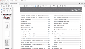
TABLE OF CONTENTS:
Crown Forklift RT 4000 Series Pallet Service Manual – PDF DOWNLOAD
Introduction 0
Important Information 1
Service personnel qualification 1
Ordering spare parts 1
Ordering documentation 1
Manual structure 1
Conventions 1
Text mark-ups in the manual 1
Brief description of equipment 1
Truck data number 3
Safety 0
Safety Notices 4
Basic Safety Notices 5
Organisational measures 5
Modifications to the truck 5
Personal safety equipment 5
Protecting the hazardous area 5
Hazards from stored energy 5
Maintenance work 5
Restoring the truck to service after maintenance work 6
Cleaning work 6
Handling batteries 6
Warning and instruction decals on the truck 6
Lifting gear and slings 6
Environmental protection 7
Safety Mechanisms and Protective Guards 8
Truck safety mechanisms 8
Truck protective guards 9
Hydraulic Schematic 0
Hydraulic Symbols 10
Hydraulic Diagram RT 4000 Series 14
Drive Unit 0
Changing the Transmission Oil 15
Change Interval 15
Permissible Oil Types 15
Preparing to change the oil 15
Draining the oil 15
Adding oil 15
Drive unit components 16
Replacing the Drive Wheel 17
Drive wheel disassembly 17
Drive wheel assembly 17
Replacing the Drive Unit 18
Special tools required 18
Disassembly 18
Assembly 18
Menu Structure 19
Operator Menu 20
Analyzer Menu A1–A2 22
Analyzer Menu A3 Outputs and A4 Test Outputs 23
Calibration Menu C1 and C3 24
Calibration Menu C2 and C4 25
Analyzer Menu A22 Access 2 26
Analyzer Menu Access 3 Inputs 27
Analyzer Menu A24 Access 81 28
Analyzer Menu A25 Access 5 29
Analyzer Menu A26 Access 10 30
Features Menu F1–F3 31
Features Menu F4–F7 32
Features Menu F8–F17 33
Features Menu F20–F30 34
Features Menu F34–F99 35
Features Menu F71–F74 36
Hour Menu H1–H5 37
Hour Menu H6 38
Events Menu E1–E3 39
Performance Menu P1–P3 40
Performance Menu P4–P11 41
Performance Menu P18–P99 42
Utilities Menu U1 Part Numbers 43
Braking System 0
Components and Operation 44
Service brake 44
Parking brake 44
Service the parking brake 45
Measure the air gap 45
Troubleshooting 45
Replace the parking brake 46
Disassemble the parking brake 46
Assemble the parking brake 46
Test the braking distance 48
Requirements 48
Performing the test 48
Braking distance table 48
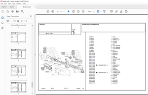
Componentry 0
RT 4020 Overview 49
RT 4040 Overview 50
Controls 51
Electrical System 52
RT 4020 Motor Compartment 52
RT 4040 Motor Compartment 53
RT 4040 Motor Compartment 54
RT 4040 Motor Compartment 54
RT 4020 and RT 4040 Motor Compartments 55
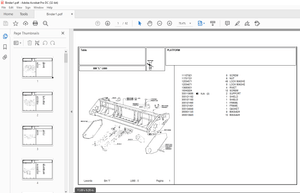
RT 4020 Platform 56
RT 4040 Platform 56
RT 4020 and RT 4040 57
Top panels removed 57
RT 4020 and RT 4040 57
Top panels removed 57
RT 4020 and RT 4040 58
Top panels removed 58
RT 4020 and RT 4040 58
Top panels removed 58
RT 4020 and RT 4040 59
Top panels removed 59
RT 4020 and RT 4040 59
Top panels removed 59
RT 4020 and RT 4040 60
Horn Button 60
RT 4020 and RT 4040 60
Battery Latch 60
RT 4020 and RT 4040 61
SAHS 61
Cylinders 0
Repairing Hydraulic Cylinders 62
Safety Notices 62
Maintenance and repair notes 62
Replacing the rod seals 62
Tools 63
Small hook 63
Extractor 63
Extractor 63
Groove aligning arbor for small rod seals 63
Assembly devices for large rod seals 64
Protective mechanisms 64
Gasket Replacement 65
Removing a large rod seal 65
Removing a small rod seal 65
Inserting a large rod seal 65
Fitting a small rod seal 66
Rod seal assembly, sealing lip first 66
Repairing Lift Cylinders 67
Hydraulic System 0
Checking and Replenishing the Hydraulic Oil Level 69
Checking the hydraulic oil level 69
Adding Hydraulic Oil 69
Adding hydraulic oil 69
Replacing the Hydraulic Oil 70
Replacing the Hydraulic Filter 71
Bleeding the Hydraulic System 73
Replacing the relief valve 74
Testing and adjusting the relief valve 75
Testing the relief valve 75
Relief valve adjustment 75
Flushing the hydraulic system 76
Requirements 76
Drift test 77
Drift test preparation 77
Drift Test 77
Hydraulic System Troubleshooting 78
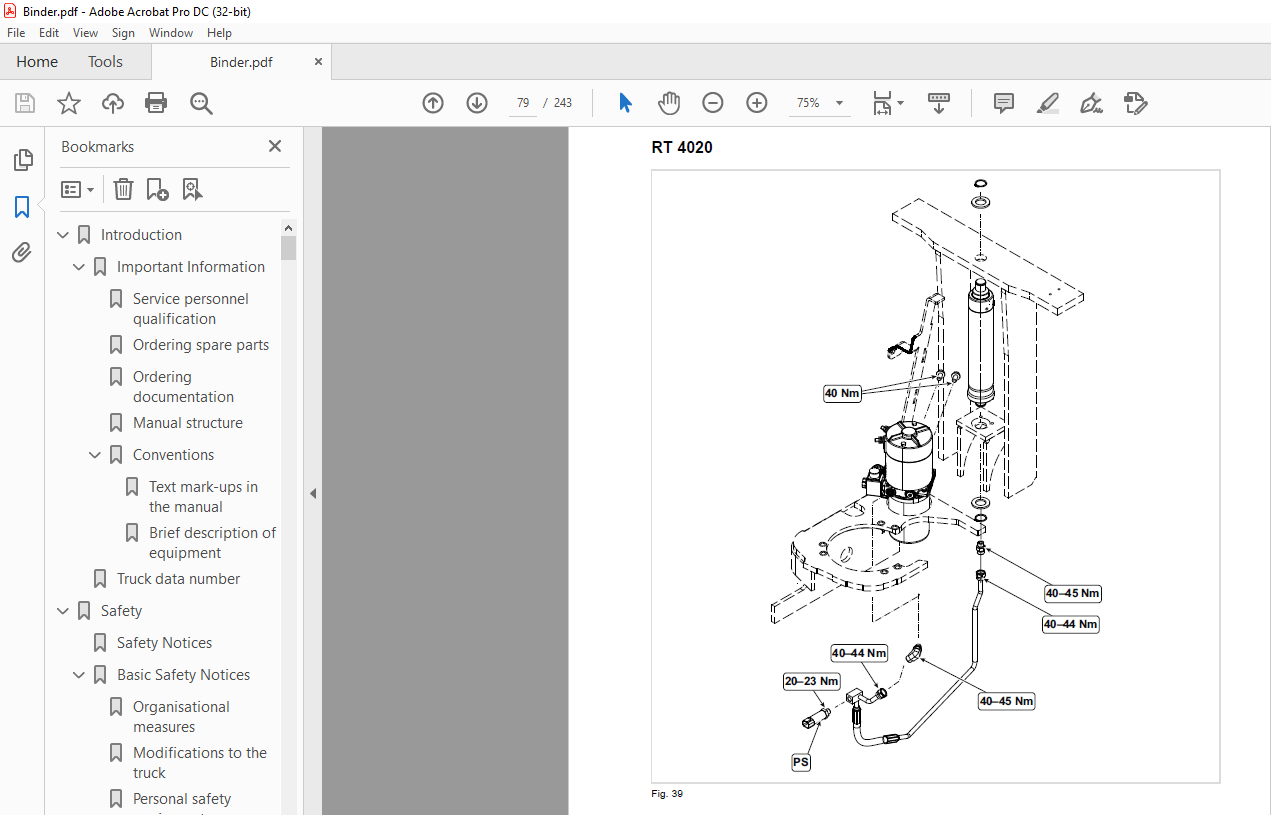
Torques 79
RT 4020 79
RT 4040 80
Inspection and Lubrication 0
Cleaning the Truck and Components 81
Effects of incorrect cleaning 81
Electrical components 81
Roller bearings and slide bearings 81
Corrosion-protected surfaces 81
Environmental protection 81
Cleaning the entire truck 81
Cleaning removed components 82
Cleaning other mechanical components 82
Lifting the Truck 83
Lifting the truck by crane 83
Securing the Truck on a Truck Bed 84
Clamping trucks with a WorkAssist™ accessory tube or load backrest 84
Clamping trucks without a WorkAssist™ accessory tube or load backrest 85
Towing the truck 86
Jacking up the truck 87
Placing the Truck in Storage 88
Taking the truck out of service 88
Testing trucks in storage 88
Returning the Truck to Service 88
Lubricants and Additives 89
Cold Store Truck Requirements 89
Abbreviations used 89
Planned Maintenance 91
Maintenance Schedule 91
Annual inspection in accordance with FEM 4004 91
Terms and Abbreviations 91
Maintenance Schedule 92
General 92
Covers 93
Hydraulic System 94
Drive Unit 95
Electrical System 96
Brake System 97
Steering 97
Lifting Mechanism 98
Cylinders 98
Platform 99
Miscellaneous 99
Repairing the Castor Wheel Assembly100
Removing the castor wheel assembly100
Installing the castor wheel assembly101
Drive wheel wear compensation101
Replacing the castor wheels102
Replacing the drive wheel104
Standard Torques105
Metric screws and nuts without flange105
Metric hex bolts and nuts with flange (Unbrako® type)105
Lifting Mechanism 0
Adjusting the Lift106
Adjust the outrigger height106
Adjust the Lift107
Gas Pressure Spring Replacement110
Electrical System 0
Selecting Service Levels112
Selecting service level 2112
Selecting service level 3112
Electrical System 0
Input Signals113
Stand-by Mode113
Electrical System 0
Parameter Settings115
Separately adjustable parameters in performance profiles P1–P3115
Identical parameters in all performance profiles115
Electrical System 0
Calibration117
Select the Calibration menu117
Calibrate the traction potentiometer117
Calibrate steering118
Requirements118
Set the maximum steer angle118
Electrical System 0
Event Codes119
Malfunctions with event code display119
Locating malfunctions119
Event code groups119
Calibrate the load sensor120
Event Code Group 100121
Event code 100121
Event Code Group 200123
Event code 202123
Event code 203125
Event code 204125
Event code 205127
Event code 208129
Event code 228130
Event code 229131
Event code 230133
Event code 231134
Event code 234136
Event Code – Group 300137
Event code 300137
Event code 301137
Event code 302138
Event code 303138
Event code 304139
Event code 305141
Event code 306141
Event code 307142
Event code 308142
Event code 309143
Event code 310144
Event code 314144
Event code 315145
Event code 316146
Event code 317147
Event code 319148
Event code 320150
Event code 321151
Event code 322152
Event code 326152
Event code 328153
Event code 329153
Event code 333154
Event code 334154
Event code 335155
Event code 337156
Event code 338156
Event code 340157
Event code 341158
Event code 342159
Event code 343160
Event code 348161
Event code 351161
Event code 353162
Event code 354163
Event code 355164
Event code 356164
Event code 357164
Event code 358166
Event code 359166
Event code 361168
Event code 362169
Event code 365169
Event code 368170
Event code 371170
Event Code Group 500172
Event codes 500–505172
Event code 506172
Event code 508173
Event code 509173
Event code 510175
Event code 511177
Event code 512177
Event code 513177
Event code 514178
Event code 515179
Event code 516179
Event code 519180
Event code 520180
Event code 522181
Event code 523181
Event code 524182
Event code 525183
Event code 527184
Event code 528184
Event code 529184
Event code 530185
Event code 532186
Event code 535187
Event code 536188
Event code 537188
Event code 538188
Event code 540190
Event code 541190
Event code 542190
Event code 543191
Event code 544192
Event code 545193
Event code 547193
Event code 550194
Event code 551194
Event code 552195
Event code 553195
Event code 554196
Event code 555197
Event code 556197
Event code 557198
Event code 558198
Event code 559199
Event code 560199
Event code 561200
Event code 562200
Event Code Group 800201
Event code 800201
Event code 801202
Event Code – Group 1000203
Event code 1000203
Event code 1001 or 1002204
Electrical System 0
Events Displayed as Text205
FPS / SES SW205
Stopped206
Traction control module hot207
Traction motor hot208
Steering controller hot209
Steer motor hot211
Electrical System 0
Checking and Adjusting the BDI Setting213
Requirements213
Checking the BDI Setting213
Adjusting the BDI setting214
Electrical System 0
Adjusting the Load Profile215
Load profile and discharge curve215
Assigning a load profile215
Electrical System 0
Replacing Traction Potentiometer on Left-hand Drive217
Electrical System 0
General DC Motor Maintenance Instructions219
Brushes219
Motor219
Rotor219
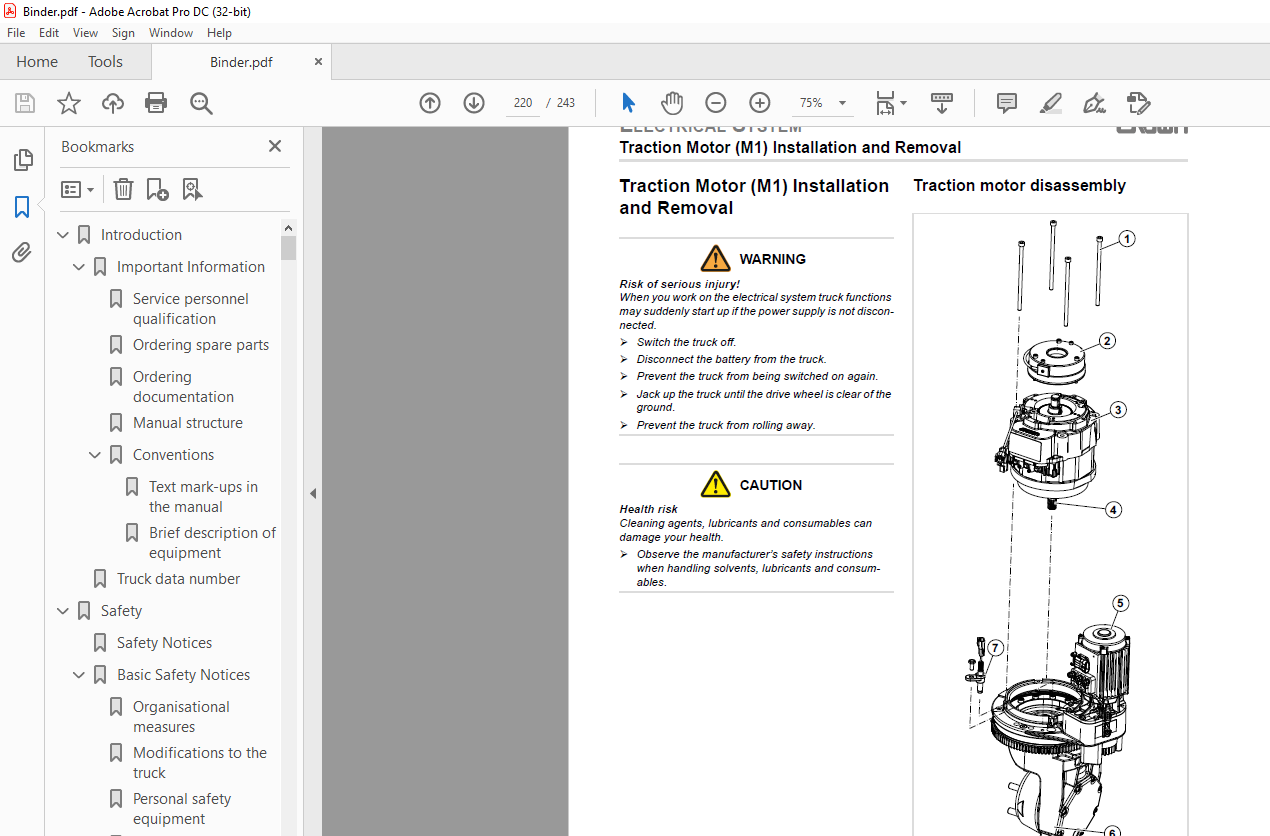
Traction Motor (M1) Installation and Removal220
Traction motor disassembly220
Traction motor assembly221
Repair the traction motor222
Preparation222
Rotor and bearing disassembly222
Rotor and bearing assembly222
Final Tasks222
Repair the pump motor (M2)223
Replace the steer motor (M3)224
Special tools required225
Steer motor disassembly225
Steer motor assembly225
Electrical System 0
Repairing Contactors226
Wear test226
Check the contacts226
Checking the coils226
Checking the springs226
Electrical System 0
PMT Test227
Required tools227
Preparing the truck for the test227
Testing Access 2227
Test Access 3228
Test Phase U228
Requirements228
Test Phase V228
Requirements228
Test Phase W228
Requirements228
Complete the PMT Test on Access 2/3229
Test Access 5229
Test Phase U229
Requirements229
Test Phase V229
Requirements229
Test Phase W229
Requirements229
Complete the PMT Test on Access 5230
Schematic Diagrams 0
Wire Colour Code231
Contact Symbol Abbreviations232
Electrical wiring diagrams234
Flow Diagram (without Options)236
Flow Diagram (with Options)237
CAN-Bus Connections238
Lithium Ion Battery Provision Option239
With Key Switch239
With Keypad240
Main Wire Harness241
Steering 0
Adjusting the SAHS242
Steering 0
Adjusting the SAHS243
IMAGES PREVIEW OF THE MANUAL:
More products