$41
Crown Forklift SC 4000 Counter Balanced Service Manual – PDF DOWNLOAD
Crown Forklift SC 4000 Counter Balanced Service Manual – PDF DOWNLOAD
FILE DETAILS:
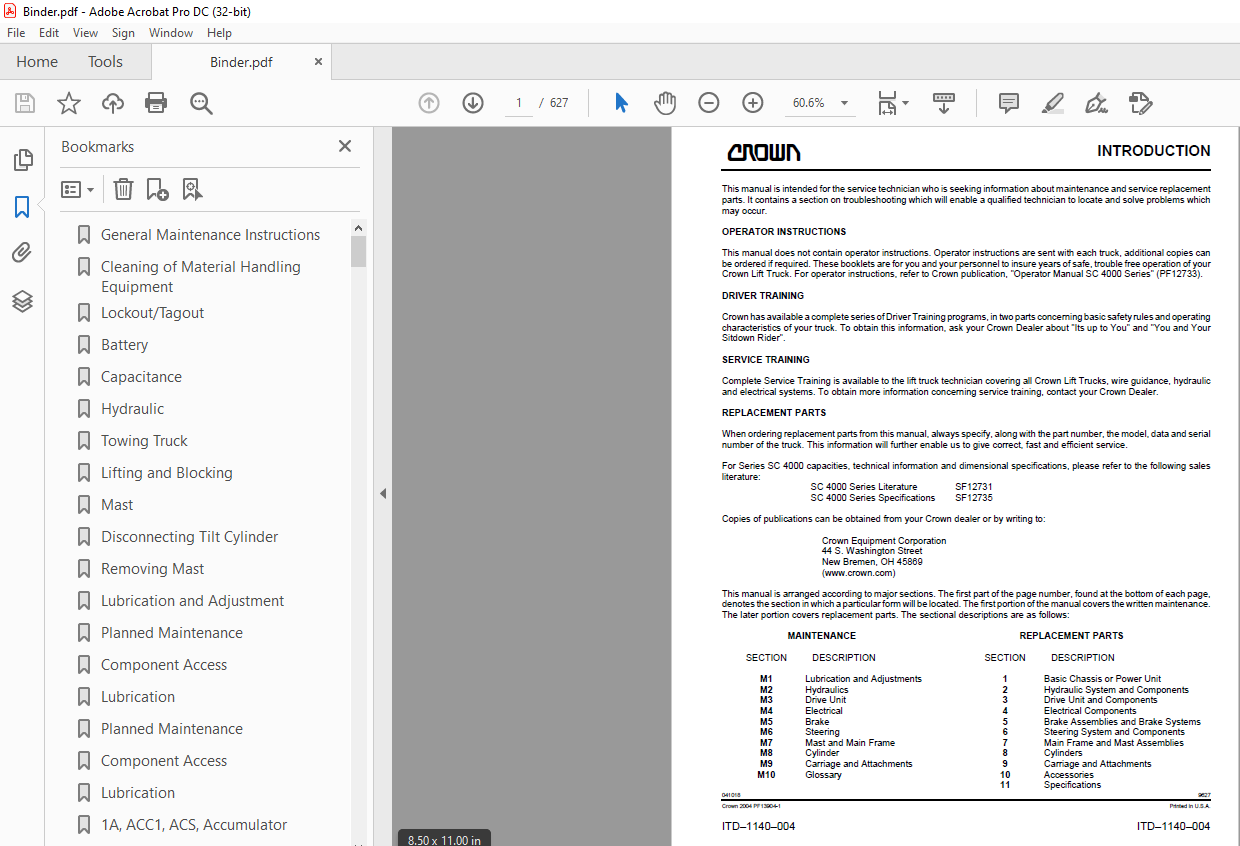
Crown Forklift SC 4000 Counter Balanced Service Manual – PDF DOWNLOAD
Language : English
Pages :627
Downloadable : Yes
File Type : PDF
TABLE OF CONTENTS:
Crown Forklift SC 4000 Counter Balanced Service Manual – PDF DOWNLOAD
General Maintenance Instructions 7
Cleaning of Material Handling Equipment 9
Lockout/Tagout 0
Battery 0
Capacitance 0
Hydraulic 0
Towing Truck 0
Lifting and Blocking 0
Mast 0
Disconnecting Tilt Cylinder 0
Removing Mast 0
Lubrication and Adjustment 0
Planned Maintenance228
Component Access 0
Lubrication 0
Planned Maintenance228
Component Access 0
Lubrication 0
1A, ACC1, ACS, Accumulator 67
ALM1, 2, AXS1, 2, BRES 68
Breather, BRS1, CBV, Cylinder (parking brake) 69
Cylinder (carriage), (lift), (steer), (tilt) 70
Display, Dipstick, Distribution Panel, DPS1, 2, 3 71
F, FAN1, 3, 4 72
FIL, Filter (return), FNS, FS 73
FU1, 2, 3, 4 74
FU5, 6, 7, 11 75
FU12, FW, Hand Pump, HGTS1 76
HN, HNS, HSS, K1 77
K2, 3, 11, 12 78
KYS, LGS1, 2, LGT1, 2, 3 79
LGT4, 5, 6, Lift/Tilt Module, M1 80
M2, 3, Manual Release Valve, MPCE 81
MRC1, 2, P1, 2 82
Pressure Check Point, PRKA, B, PS, PS1 83
Pump, R, RAS 84
RB, RES1, 2, 3 85
RS, RV1, 2, 3 86
S, SB60, 80, SCU 87
Sensor1, 2, 3, SES1, 2 88
Strainer, SV1, 2, TBS 89
THS1, 2, TLMS, TLT 90
TMM, ULV, Valve 91
Lines, Fittings, Reservoir183
Drift Test184
Bleeding184
General187
Steering and Brake189
Steer Left191
Steer Right192
Service Brake Applied193
Service Brake Released194
Lift195
Lower196
Tilt Back197
Tilt Forward198
Sideshift – Left199
Sideshift – Right200
Hydraulic Circuitry201
Steer & Brake Circuit203
Steer Left Circuit205
Steer Right Circuit206
Service Brake Applied Circuit207
Service Brake Released Circuit208
Lift Circuit209
Lower Circuit210
Tilt Back Circuit211
Tilt Forward Circuit212
Sideshift – Left Circuit213
Sideshift – Right Circuit214
Hydraulic Schematic Symbols215
Hydraulic Schematic Symbols219
Pump – Gear 0
Oil Seal Removal 0
Oil Seal Replacement 0
Pump Disassembly 0
Parts Inspection 0
Pump Reassembly 0
Start Up Procedure 0
Steer Pump228
AXS1, AXS2, TLT257
RAS258
TBS, ACS259
BRS1, BRS2, HBS260
HGTS1, SES1, SES2261
TLMS262
Wiring Color Codes276
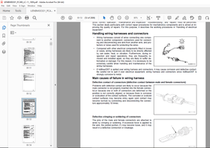
Wiring Harness277
Power Cables277
Symbol Nomenclature278
Symbols279
Wiring Color Codes281
Wiring Harness282
Power Cables282
Symbol Nomenclature283
Symbols284
Handset Operation290
Controller Settings292
GEN II SX Troubleshooting294
Handset Operation294
Event Code Access295
Battery State of Charge295
Hour Meter296
Welding296
Recommended Lubrication of Pins and Sockets296
Initial Troublehsooting Instructions297
Controller Replacement Information297
Disabling RS232 Communications297
Setting Function Code 25297
Moving Handset From Controller To Controller298
Returing Truck To Service298
Event Code Display Description298
Slave Controller (MRC2) Event298
Master Controller (MRC1) Event298
No Code Displayed299
-201 thru -299394
-301 thru – 399394
GEN II SX Troubleshooting395
Handset Operation395
Event Code Access396
Battery State of Charge396
Hour Meter397
Welding397
Recommended Lubrication of Pins and Sockets397
Initial Troublehsooting Instructions398
Controller Replacement Information398
Disabling RS232 Communications398
Setting Function Code 25398
Moving Handset From Controller To Controller399
Returing Truck To Service399
Event Code Display Description399
Slave Controller (MRC2) Event399
Master Controller (MRC1) Event399
No Code Displayed400
Handset506
ACC POT507
STR POT508
Brake Resistor Module510
Auto Calibration of Potentiometers511
Handset513
ACC POT514
STR POT515
Brake Resistor Module517
Auto Calibration of Potentiometers518
Inspection523
Component Replacement524
104483, 111634524
104140, 106109, 112220, 125707, 126209526
Adjustment545
Friction Plate and Rotor Replacement546
Removal547
Installation549
Troubleshooting550
Steer Unit570
Steering Control Unit Disassembly570
Steering Control Unit Assembly573
Fork Inspection 0
Cylinders597
Lift Cylinder597
Disassembly597
Seals597
Seal Removal597
Seal Installation – General598
Rod U-Cup Installation598
Small U-Cup598
Large U-Cup598
Cylinder U-cup Installation599
Cylinder Assembly599
Cylinder Bleeding and Flushing600
Bleeding – Free Lift Cylinder600
Bleeding – Stage Lift Cylinders600
Flushing – Stage and Free Lift Cylinders600
Drift Test600
M10-1140-008611
M10-1140-009612
M10-1140-010613
M10-1140-011614
M10-1140-012615
M10-1140-013616
M10-1140-014617
M10-1140-015618
Audible Indicators619
Battery619
Connections619
Contactors622
Controllers623
Fans623
Fuses623
Lights624
Meters624
Motors624
Potentiometers625
Relays625
Resistors625
Solenoid Valves626
Suppressor Blocks626
Switches626
IMAGES PREVIEW OF THE MANUAL:
S.M 08/24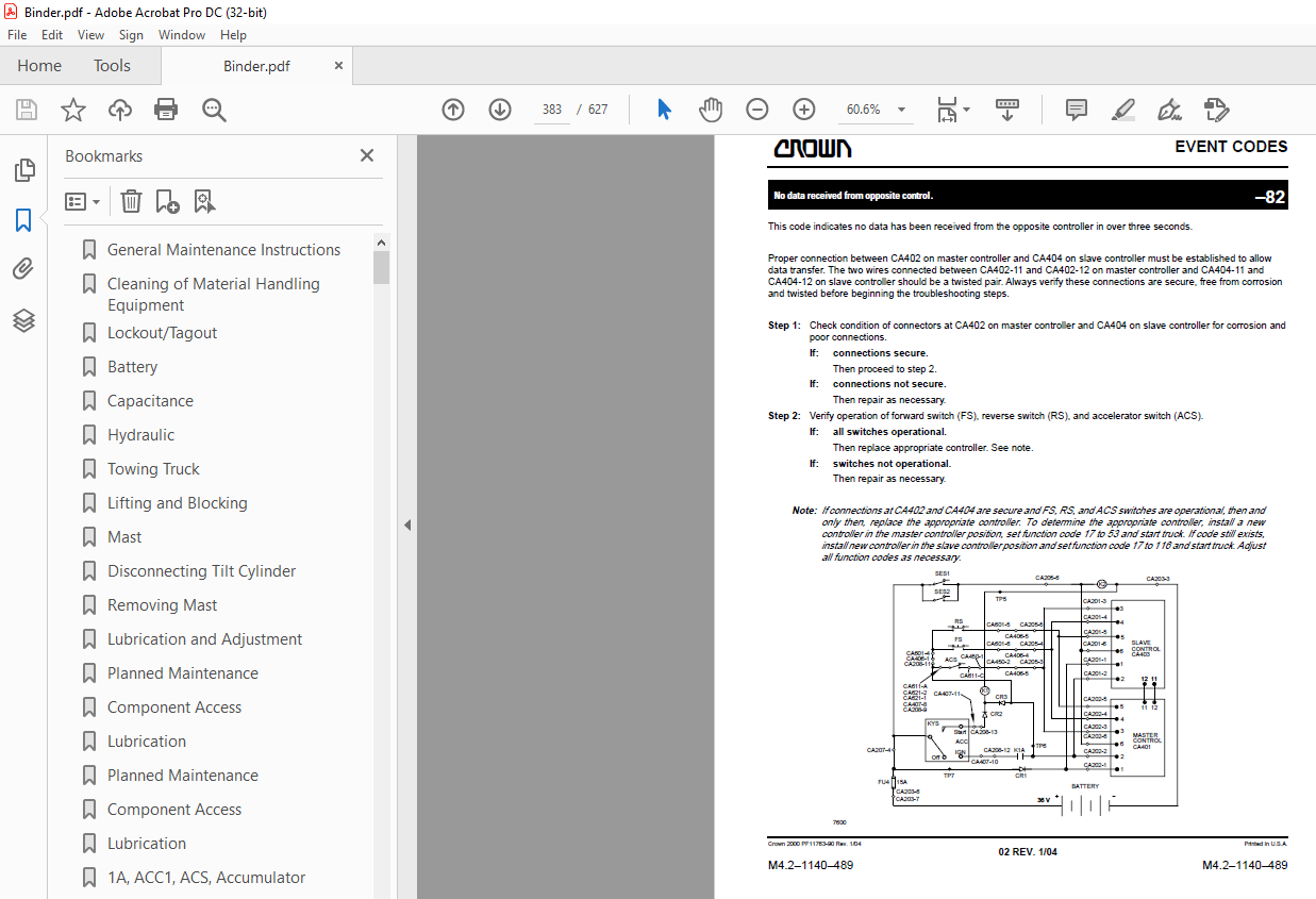
More products