$38
Crown Forklift SC 5700 Series Counter Balanced Service Manual – PDF DOWNLOAD
Crown Forklift SC 5700 Series Counter Balanced Service Manual – PDF DOWNLOAD
FILE DETAILS:
Crown Forklift SC 5700 Series Counter Balanced Service Manual – PDF DOWNLOAD
Language : English
Pages :432
Downloadable : Yes
File Type : PDF
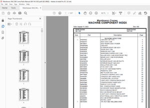
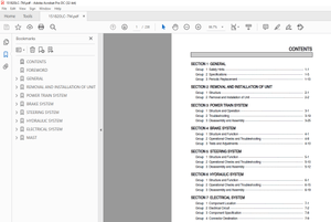
TABLE OF CONTENTS:
Crown Forklift SC 5700 Series Counter Balanced Service Manual – PDF DOWNLOAD
General Maintenance Instructions 9
Cleaning of Material Handling Equipment 11
Control of Hazardous Energy 0
Operator’s Daily Checklist 27
Lubricants, Aerosols, and Service Supplies 0
Metric Torque Values 61
Grade 61
SAE Torque Values 65
Grade 65
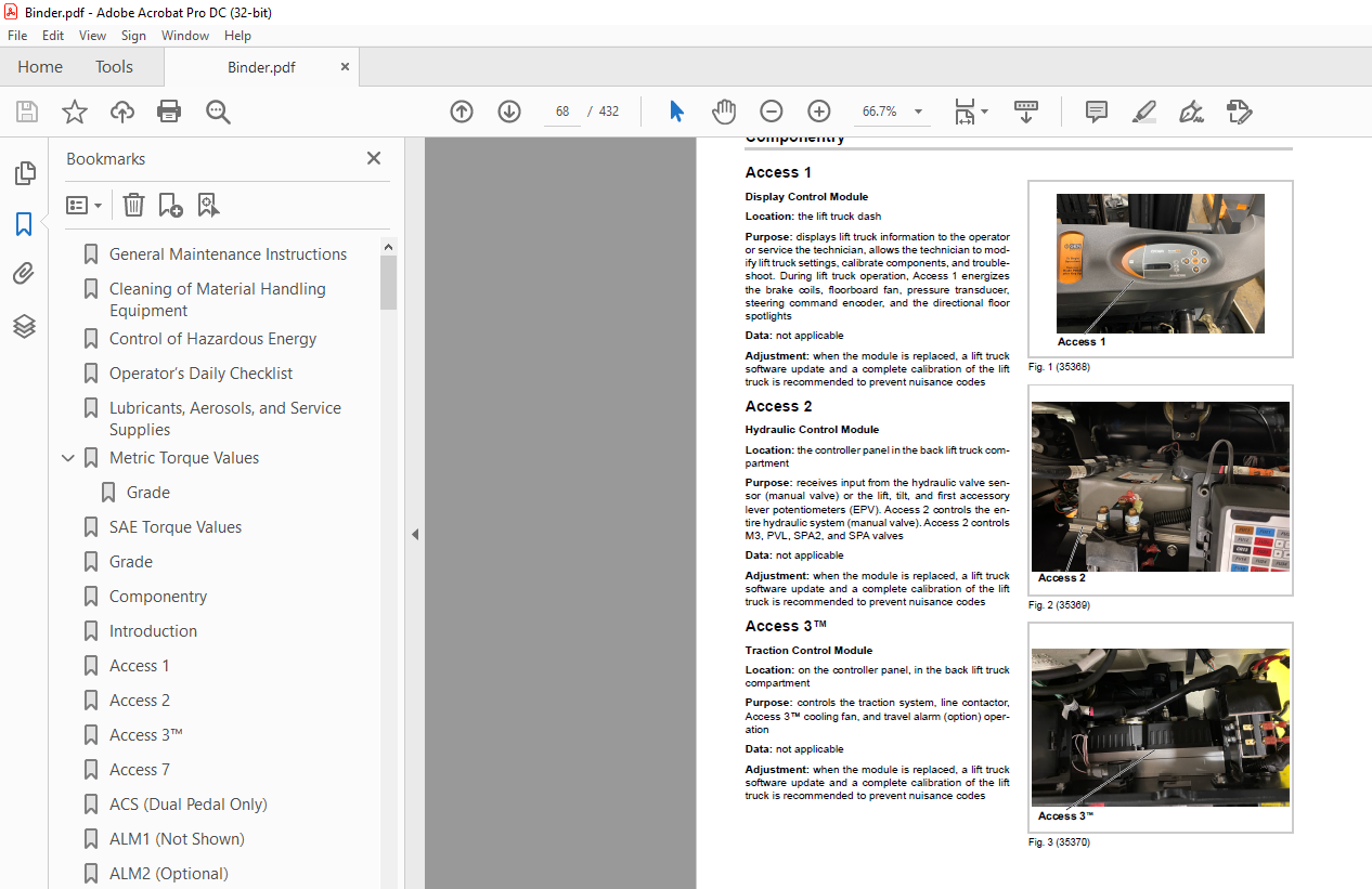
Componentry132
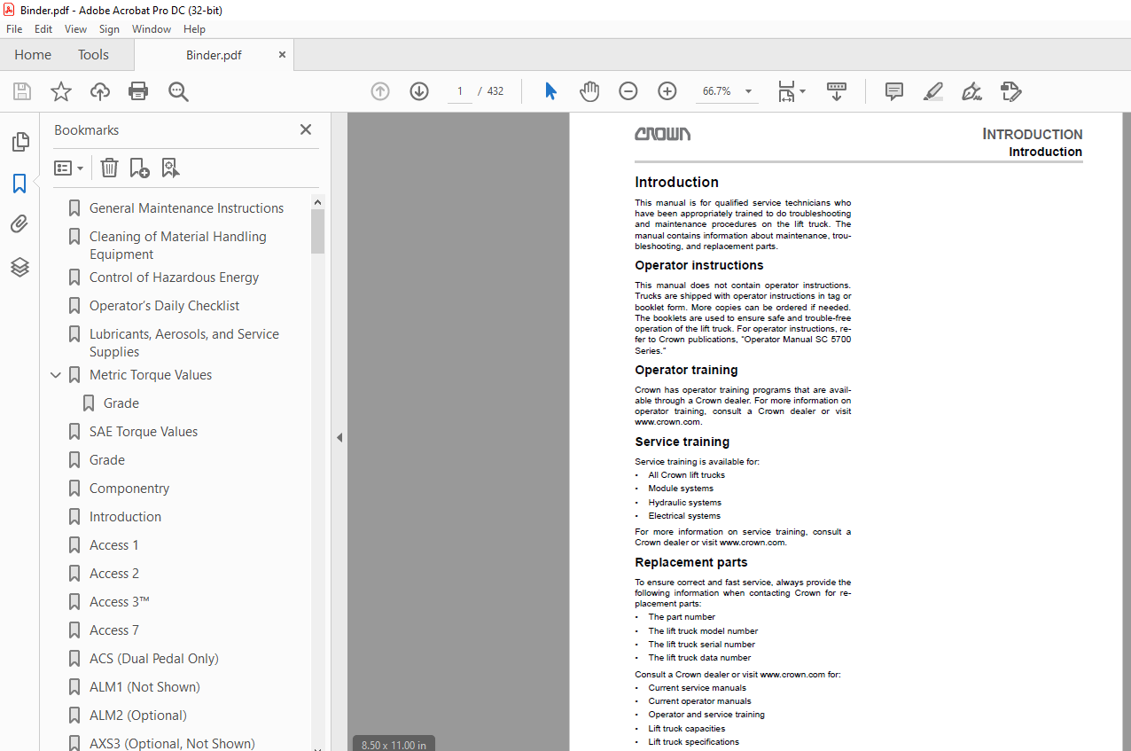
Introduction 0
Access 1 0
Access 2 0
Access 3™ 0
Access 7 0
ACS (Dual Pedal Only) 0
ALM1 (Not Shown) 0
ALM2 (Optional) 0
AXS3 (Optional, Not Shown) 0
BRES 0
BRK1 0
BRK2 0
BRKS 0
C KEY 0
C LINE 0
CBVE (EPV Only) 0
CBVR (EPV Only) 0
CLS (Optional, Not Shown) 0
CR13 0
CR184 (Not Shown) 0
CVLSA1 0
CVLSA2 0
CVLSI (EPV with Second Accessory) 0
CVLST (EPV Only) 0
CVR (EPV Only) 0
DC1 (Optional) 0
DC2 (Optional, Not Shown) 0
DFRS (Optional) 0
DR1 (Optional, Not Shown) 0
DR93 (Optional, Not Shown) 0
DR94 (Optional, Not Shown) 0
ECR1 0
ECR2 0
ECR3 0
ECR4 0
FAN1 0
FAN3 (Optional) 0
FAN4 (Optional) 0
FB IMP SNS (Optional, Not Shown) 0
FB PROX SNS (Optional, Not Shown) 0
FNS (Optional) 0
FS (EPV or Foot-Operated Directional Control Pedal Only) 0
FSR (Optional) 0
FU EWS (Optional, Not Shown) 0
FU FAN (Optional, Not Shown) 0
FU SEAT (Optional, Not Shown) 0
FU1 0
FU2 0
FU11 (Optional) 0
FU12 0
FU14 0
FU15 0
FU16 (Optional) 0
FU17 (Optional) 0
FU21 0
FU22 0
FU23 0
FU24 0
FU25 (Optional) 0
FU31 (Optional) 0
FU34 (Optional) 0
FU35 (Optional) 0
FU36 0
FU41 (Optional) 0
FU42 (Optional) 0
FU51 (Optional) 0
FU61 (Optional) 0
FU62 0
FU63 (Optional) 0
FU64 (Optional) 0
FU65 (Optional) 0
FU84 (Optional, Not Shown) 0
FU89 (Optional, Not Shown) 0
FU90 (Optional, Not Shown) 0
FWPS (Optional) 0
H20 (Optional, Not Shown) 0
HAZS (Optional) 0
HGTS1 0
HGTS2 (Optional – Not Shown) 0
HGTS3 (Optional, Not Shown) 0
HLGS (Optional) 0
HN1 0
HNS1 0
HNS2 (Not Shown) 0
HNS3 (Not Shown) 0
HNS4 (EPV Only) 0
HNS5 (Not Shown) 0
Hydraulic Valve Sensor (Manual Valve Only) 0
K4 0
K5 (Optional) 0
K20 (Optional) 0
KYS 0
LGS1 (Optional) 0
LGS2 (Optional) 0
LGT1 (Optional) 0
LGT2 (Optional) 0
LGT3 (Optional) 0
LGT4 (Optional) 0
LGT5 (Optional) 0
LGT6 (Optional) 0
LGT7 (Optional) 0
LGT8 (Optional) 0
LGT9 (Optional) 0
LGT10 (Optional) 0
LGT11 (Optional) 0
LGT WN11 (Optional, Not Shown) 0
LGT WN12 (Optional, Not Shown) 0
LGT WN13 (Optional, Not Shown) 0
LGT WN15 (Optional, Not Shown) 0
LGT WN16 (Optional, Not Shown) 0
LSPFD 0
M1 0
M2 0
M3 0
M20 (Optional) 0
M21 (Optional) 0
M22 (Optional – Not Shown) 0
MVL (EPV Only) 0
OC1 (Manual Valve Only) 0
OC2 (Manual Valve Only) 0
ORF1 (EPV Only) 0
ORF2 (EPV Only, Not Shown) 0
ORF3 (EPV Only, Not Shown) 0
ORF4 (EPV Only, Not Shown) 0
ORF5 (EPV Only, Not Shown) 0
ORF6 (EPV Only, Not Shown) 0
ORF7 (EPV with Second Accessory Only, Not Shown) 0
ORS (EPV Only, Not Shown) 0
P1 0
PCA (EPV Only) 0
PCA1 (EPV Only) 0
PCA2 (EPV With Second Accessory Only) 0
PCL (EPV Only) 0
PCT (EPV Only) 0
POT1 0
POT2 0
POT3 0
POT4 (EPV Only) 0
POT5 (EPV Only) 0
POT6 (EPV Only) 0
POT7 (EPV Only) 0
POT9 0
PROX (Optional, Not Shown) 0
PT1 (Not Shown) 0
PTC1 0
PTC2 0
RES20 (Optional, Not Shown) 0
RES21 (Optional) 0
RS (Not Shown) 0
RV1 (Manual Valve Only) 0
RV2 (Manual Valve Only) 0
RVA (EPV Only) 0
RVM (EPV Only) 0
RWPS (Optional) 0
SBS (Optional) 0
SES 0
SPA1 (EPV Only) 0
SPA2 (EPV Only) 0
SPL (EPV Only) 0
SPT (EPV Only) 0
SV1 (Manual Valve Only) 0
SV2 (Manual Valve Only) 0
SVBY (EPV Only) 0
SVC1 (Manual Valve Only, Optional, Not Shown) 0
SVL (EPV Only) 0
SVLSD (EPV Only – Optional) 0
SVX (Manual Valve Only, Optional, Not Shown) 0
TLMS 0
TPAS (Optional) 0
TS1 (Not Shown) 0
TS2 (Not Shown) 0
TS3 (Not Shown) 0
TSS (Optional) 0
VTS (Optional) 0
Hydraulic System 0
Hydraulic Schematic Symbols124
Steer Pump132
Pump Maintenance132
Fig 1 (35593)132
General132
Disassembling the pump132
Parts inspection132
Pump132
Priority valve132
Coupler132
O-ring133
Assembling the pump133
Start up procedure133
Before proceeding, Review the Control of Hazardous Energy, Lockout/Tagout and Hydraulic Sections of this manual133
Encoders134
Operation134
Wire designations134
Testing the encoders134
Channel feedback overview134
Index voltage overview135
Wiring Color Codes 0
Power Cables132
Switches 0
Battery298
Safety Rules298
Checking298
Battery Care299
Charging299
Battery Removal and Installation299
Left Side Cover Adjustment301
Right Side Cover Adjustment301
Battery Cleaning301
Troubleshooting301
Checking the Battery Under Load302
Dual Voltage Conversion302
Battery Discharge Interrupt Performance (P4)303
Battery Retainer Installation & Setup305
Event Code Introduction306
Steering – 3 Wheel312
Steer Control Unit312
Steering Column Assembly312
Steer Axle Assembly317
IMAGES PREVIEW OF THE MANUAL:
More products