$43
Crown Forklift SC 6000 Series Counter Balanced Service Manual – PDF DOWNLOAD
Crown Forklift SC 6000 Series Counter Balanced Service Manual – PDF DOWNLOAD
FILE DETAILS:
Crown Forklift SC 6000 Series Counter Balanced Service Manual – PDF DOWNLOAD
Language : English
Pages :792
Downloadable : Yes
File Type : PDF
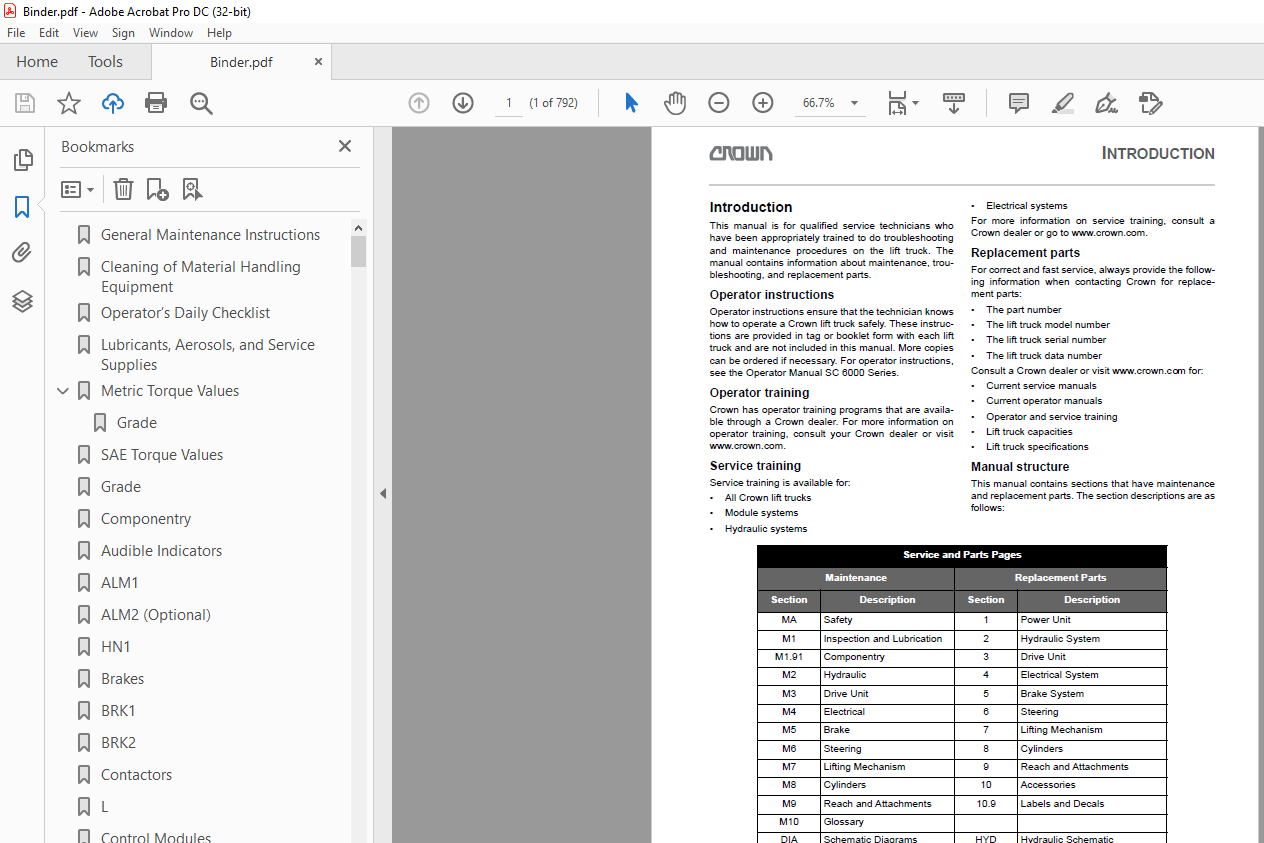
TABLE OF CONTENTS:
Crown Forklift SC 6000 Series Counter Balanced Service Manual – PDF DOWNLOAD
General Maintenance Instructions 11
Cleaning of Material Handling Equipment 13
Operator’s Daily Checklist 25
Lubricants, Aerosols, and Service Supplies 0
Metric Torque Values 67
Grade 67
SAE Torque Values 71
Grade 71
Componentry 73
Audible Indicators 74
ALM1 74
ALM2 (Optional) 74
HN1 74
Brakes 76
BRK1 76
BRK2 76
Contactors 76
L 76
Control Modules 78
Access 1 78
Access 2 78
Access 3™ 78
Access 7 (EPV Only) 78
DC1 (Option) 80
DC2 (Option) 80
Manual Valve Diagrams: DIA-1161-032 (C-2) 80
DR1 (Optional) 80
DR2 (EPV Only-Not Shown) 80
FLS 80
InfoLink® Display Module (Option) 80
Cylinders 82
Carriage Cylinder 82
Mast Cylinder 82
Sideshift Cylinder 82
Steer Cylinder-Three Wheel 82
Steer Cylinder-Four Wheel 82
Tilt Cylinder 82
Encoders 84
ECR1 84
ECR2 84
ECR3 84
ECR4 86
Fans 86
FAN1 86
FAN3 (Option) 86
FAN4 (Option-Not shown) 86
Fuses 88
FU1 88
FU2 88
FU4 88
FU5 88
FU6 90
FU7 (Option-Not Shown) 90
FU8 (Not Shown) 90
FB421 (Option) 90
FU17 (Option – not shown) 90
FU18 (Option – not shown) 90
FU19 (Option – not shown) 90
FU20 (Option – not shown) 92
Parts breakdown: N/A 92
FU30 (Option – not shown) 92
Parts breakdown: N/A 92
FU31 (Option – not shown) 92
FU40 (Option – not shown) 92
FU41 (Option – not shown) 92
FU42 (Option – not shown) 92
FU43 (Option – not shown) 93
FU44 (Option – not shown) 93
Lights 94
DS20 (Manual Valve Only-Option) 94
LGT1 (Option) 94
LGT2 (Option) 94
LGT3 (Option) 94
LGT4 (Option) 96
LGT5 (Option) 96
LGT6 (Option) 96
LGT7 (Option) 98
LGT8 (Option) 98
LGT9 (Option) 98
LGT10 (Option) 98
LGT11 (Option – Not shown) 98
Manifolds100
Carriage Relief Manifold-1st Accessory-Not Shown100
Carriage Relief Manifold-2nd Accessory-Not Shown100
EPV Manifold (EPV Only)100
Lowering Flow Control Manifold (Manual Valve Only)100
Operator Presence Manifold (Manual Valve Only)100
Tilt Manifold (Manual Valve Only)102
Two Accessories Manifold (EPV Only)102
Miscellaneous102
PT1102
Filter102
Reservoir102
Steer Unit102
Breather104
H20 (Option – Not Shown)104
Suction Strainer106
Motors106
M1106
M2106
M3108
M20 (Option – Not Shown)108
Parts breakdown: 011-1161-003 (30) (36)108
M21 (Option – Not Shown)108
M22 (Option – Not Shown)108
Potentiometers110
POT1110
POT2110
POT3112
POT4112
POT5 (EPV Only)112
POT6 (EPV Only)112
POT7 (EPV Only)114
Pumps114
Relays114
K1114
K2 (Manual Valve Only)114
K3 (EPV Only)114
K4 (Option)116
K20 (Option)116
Resistors118
RES2 (Option)118
RES3 (Option)118
RES50 (Option-Not Shown)118
RES20 (Option – not shown)118
RES21 (Option – not shown)118
Sensors120
Impact Sensor120
PT1120
THS1 (Option)120
THS2 (Option)120
TS1122
TS2122
TS3122
Solenoids124
SPA1 (EPV Only-Option)124
SPA2 (EPV Only-Option)124
SPL (EPV Only)124
SPT (EPV Only)126
SVA4 (EPV Only, Option-Not Shown)126
SV1 (Manual Valve Only)126
SV3 (Manual Valve Only)128
SVBy (EPV Only)128
SVL (EPV Only)128
SVLSD (EPV Only-Option)130
SVOP (Manual Valve Only)130
SVX (Manual Valve Only, Option-Not Shown)130
Suppressors132
CR1132
CR2132
CR3132
CR4132
CR5132
CR6132
SB80 (Option-Not Shown)134
TR1134
TR2134
Switches136
ACS136
AXS1 (Manual Valve Only-Option)136
AXS2 (Manual Valve Only-Option) Second Accessory Function Switch136
AXS3 (Manual Valve Shown-Option)136
BRES (Option)138
BRKS1138
BRKS2 (Option)138
CLS (Option-EPV Valve Only, Not Shown)138
FS140
HGTS1140
HGTS2 (Option-Not Shown)140
HGTS3 (Option-Not Shown)142
HNS1142
HNS2-Not Shown142
HNS3-Not Shown142
HNS4 – (EPV Only)144
KYS144
LGS1 (Option)144
LGS2 (Option)144
ORS (EPV Only – Not Shown)146
ORS1 (Manual Valve Only – Not Shown)146
ORS2 (Manual Valve Only – Not Shown)146
ORS3 (Manual Valve Only – Not Shown)146
RS148
SBS (Option)148
SES148
TBS (Manual Valve Only)148
THS1, THS2150
TLMS150
TLT (Manual Valve Only)150
TPAS (Option)150
TSS (Option)150
VTS150
HLGS (Option)152
FWPS (Option)152
RWPS (Option)152
DFRS (Option)152
HAZS (Option)152
Valves154
CBVE154
CBVR154
Control Valve (Manual Valve Only)154
CVLSA1 (EPV, Only)154
CVLSA2 (EPV, Only)156
CVLSI (EPV, Two Accessories Only)156
CVLST (EPV Only)156
CVR (EPV Only)156
EPV156
Flow Regulator156
MPCE (Manual Valve Only)158
MVL158
Load Sense Priority Flow Divider158
ORF1 (EPV Only)158
ORF2 (EPV Only)158
ORF3 (EPV Only)160
ORF4 (EPV Only)160
ORF5 (EPV Only)160
ORF6 (EPV Only)160
ORF7 (EPV Only)160
PCA (EPV Only)162
PCA1 (EPV Only)162
PCA2 (EPV Only)162
PCL (EPV Only)162
PCT (EPV Only)162
Quick Disconnect164
RV1 (Manual Valve Only)164
RV2 (Manual Valve Only)164
RVA (EPV Only)164
RVM (EPV Only)164
SPA1, SPA2, SPL, SPT, SV1, SV3, SVBy, SVL, SVLSD, SVOP SVX164
Velocity Fuse166
Hydraulic System253
Hydraulic Reservoir and Filters255
Reservoir255
Hydraulic Circuitry257
Manual Steering Circuit257
No Demand for Steering Circuit (Manual Valve)258
Steering Left Circuit (Manual Valve)262
Steering Left Circuit (EPV)264
Steering Right Circuit (Manual Valve)266
Steering Right Circuit (EPV)268
Lift Circuit (Manual Valve)270
Lift Circuit (EPV)272
Lower Circuit (Manual Valve)274
Lower Circuit (EPV)276
Tilt and Accessory Flow (EPV)278
Tilt Back Circuit (Manual Valve)280
Tilt Back Circuit (EPV)282
Tilt Forward Circuit (Manual Valve)284
Tilt Forward Circuit (EPV)286
Sideshift Left Circuit (Manual Valve)288
Sideshift Left Circuit (EPV – Lift Trucks with One Accessory)290
Sideshift Right Circuit (Manual Valve)292
Sideshift Right Circuit (EPV – Lift Trucks with One Accessory)294
Accessory Circuit (EPV – Lift Trucks with Two Accessories)296
Hydraulic Schematic Symbols299
Pump Maintenance303
Prepare the lift truck for maintenance303
Directional Control Valve – Manual308
Drive Unit Repair324
Encoders371
Operation371
Wire designations371
Testing the encoders371
Channel feedback overview371
Index voltage overview372
Dual Pedal393
Access 1 2 3® Menus 0
Operator level 0
Messages and menus 0
ANALYZER Menus 0
ANALYZER menu overview 0
SERVICE LEVEL 2: 0
SERVICE LEVEL 3: 0
ANALYZER menu access 0
A1 STATUS menu descriptions 0
A2 INPUTS menu descriptions 0
A21 ACCESS 1 INPUTS menu 0
A22 ACCESS 2 INPUTS menu 0
A23 ACCESS 3™ INPUTS menu 0
A27 ACCESS 7 INPUTS menu 0
A210 EPS INPUTS menu 0
A3 OUTPUTS menu descriptions 0
A31 ACCESS 1 OUTPUTS menu 0
A32 ACCESS 2 OUTPUTS menu 0
A33 ACCESS 3™ OUTPUTS menu 0
A37 ACCESS 7 OUTPUTS menu 0
A4 TEST OUTPUTS menu descriptions 0
A41 ACCESS 1 TEST OUTPUTS menu 0
A42 ACCESS 2 TEST OUTPUTS menu 0
A43 ACCESS 3™ TEST OUTPUTS menu 0
A47 ACCESS 7 TEST OUTPUTS menus 0
FEATURES Menus 0
FEATURES menu overview 0
FEATURES menu access 0
F1 LANGUAGE menu descriptions 0
F2 UNITS OF MEASURE menu descriptions 0
F3 VEHICLE DATA NUMBER menu descriptions 0
F4 HYDRAULIC VALVE TYPE menu descriptions 0
F5 ELECTRICAL POWER SOURCE menu descriptions 0
F7 FANS menu descriptions 0
F8 MESSAGE MODE menu descriptions 0
F9 HOUR METER menu descriptions 0
F10 USER PERFORMANCE menu descriptions 0
F11 USER CODES menu descriptions 0
F20 OPTIONS menu descriptions 0
PERFORMANCE Menus 0
PERFORMANCE menu overview 0
OPERATOR: 0
SERVICE LEVEL: 0
PERFORMANCE menu access 0
PX1 ACCEL menu descriptions 0
PX2 MAX TRAVEL SPEEDS menu descriptions 0
PX3 POWER menu descriptions 0
PX4 ACCY1 SPEED menu descriptions 0
PX5 ACCY2 SPEED menu descriptions 0
PX6 TILT SPEED menu descriptions 0
PX7 LIFT SPEED menu descriptions 0
PX8 LIFT ACCEL menu descriptions 0
PX9 LOWER SPEED menu descriptions 0
PX10 LOWER ACCEL menu descriptions 0
PX11 TILT ACCEL menu descriptions 0
PX12 ACCY1 ACCEL menu descriptions 0
PX13 ACCY2 ACCEL menu descriptions 0
PX14 LIFT DECEL menu descriptions 0
PX15 LOWER DECEL menu descriptions 0
PX16 TILT DECEL menu descriptions 0
PX17 ACCY1 DECEL menu descriptions 0
PX18 ACCY2 DECEL menu descriptions 0
P4 SOC menu descriptions 0
P5 PLUG menu descriptions 0
P6 COAST menu descriptions 0
P8 PERFORMANCE > FL menu descriptions 0
P9 STEER SPEED menu descriptions 0
P10 SPEED LIMIT menu descriptions 0
P11 ZONE DECEL menu descriptions 0
P99 LOAD FACTORY DEFAULTS menu descriptions 0
CALIBRATION Menus 0
Necessary calibrations 0
CALIBRATION menu access 0
C1 ACCEL POT menu 0
C2 BRAKE POT menu 0
C3 STEER POT menu 0
C4 LIFT POT menu 0
C4 HYDRAULIC LEVERS menu 0
C41 LIFT POT menu 0
C42 TILT POT menu 0
C43 ACCESSORY 1 POT menu 0
C44 ACCESSORY 2 POT menu 0
C5 ADJUST BATTERY menu 0
C6 HYDRAULIC VALVES menu 0
C61 LOWER VALVE menu 0
C62 TILT VALVES menu 0
C63 ACCESSORY 1 VALVES menu 0
C64 ACCESSORY 2 VALVES menu 0
HOUR Menus 0
HOUR menu overview 0
OPERATOR: 0
SERVICE LEVEL 2: 0
SERVICE LEVEL 3: 0
HOUR menu access 0
EVENTS Menus 0
EVENTS menu overview 0
EVENTS menu access 0
UTILITIES Menus 0
UTILITIES menu overview 0
UTILITIES menu access 0
U1 PART NUMBERS menu descriptions 0
U2 TOW MODE menu descriptions 0
U3 TRUCK LOCKOUT menu descriptions 0
U4 CLEAR EEPROM menu descriptions 0
U5 EPS menu descriptions 0
Index 0
Schematic – AC Lift Lever – EPV 0
Back of Lift Truck – EPV 0
Lift Truck Splices – EPV 0
Armrest – EPV 0
Front of Lift Truck 1 – EPV 0
Front of Lift Truck 1 – EPV – Dual Pedal 0
Access 1 – EPV 0
Hydraulics – EPV 0
Front of Lift Truck 2 – EPV 0
Overhead Guard Lights 0
Infolink® 0
Schematic – Cabin 0
Fuse Box – Cabin 0
Power Panel – Cabin 0
Front of Overhead Guard – Cabin 0
Back of Overhead Guard – Cabin 0
Switch Pod – Cabin 0
Power Cables 0
Wire Harnesses – EPV 0
Schematic – AC Lift Lever – Manual Valve 0
Back of Lift Truck – Manual Valve 0
Lift Truck Splices – Manual Valve 0
Access 3™ – Manual Valve 0
Access 2 – Manual Valve 0
Front of Lift Truck 1 – Manual Valve 0
Front of Lift Truck 1 – Manual Valve – Dual Pedal 0
Access 1 – Manual Valve 0
Hydraulics – Manual Valve 0
Front of LIft Truck 2 – Manual Valve 0
Overhead Guard Lights 0
Infolink® 0
Schematic – Cabin 0
Fuse Box – Cabin 0
Power Panel – Cabin 0
Front of Overhead Guard – Cabin 0
Back of Overhead Guard – Cabin 0
Switch Pod – Cabin 0
Power Cables 0
Wire Harnesses – Manual Valve 0
Access 3™ – EPV 0
Access 2 – EPV 0
Electrical Diagram Index 0
EPV – Schematic 0
EPV – Rear of Lift Truck – Power / CAN – Distribution Panel 0
EPV – Access 3™ 0
EPV – Front of Lift Truck 0
EPV – Front of Lift Truck – Dual Pedal 0
EPV – Access 1 0
EPV – Hydraulics 0
EPV – Front of Lift Truck – Light Options 0
Overhead Guard Worklights 0
Overhead Guard Floor Spotlights 0
Hard Cabin – Schematic – Part One 0
Hard Cabin – Schematics – Part Two 0
Hard Cabin – Fuse Box 0
Hard Cabin – Power Panel 0
Hard Cabin – Rear of Overhead Guard 0
Hard Cabin – Front of Overhead Guard 0
Hard Cabin – Switch Pod 0
EPV – Freezer Condition – EPS Options 0
InfoLink® 0
Power Cables 0
EPV – Wiring Harnesses 0
160047-001 0
155492 0
155493 0
155515 0
155516 0
158086 0
158088 0
158089 0
160000-002 0
160001-001 0
159927-002 0
164045-003 0
164045-006 0
164047 0
Manual Lever – Schematic 0
Manual Lever – Rear of Lift Truck – Power / CAN – Distribution Panel 0
Manual Lever – Access 3™ 0
Manual Lever – Access 2 0
Manual Lever – Rear of Lift Truck – Switches and Sensors 0
Manual Lever – Splices 0
Manual Lever – Front of Lift Truck 0
Manual Lever – Front of Lift Truck – Dual Pedal 0
Manual Lever – Access 1 0
Manual Lever – Hydraulics 0
Manual Lever – Front of Lift Truck – Light Options 0
Overhead Guard Worklights 0
Overhead Guard Floor Spotlights 0
Hard Cabin – Schematic – Part One 0
Hard Cabin – Schematic – Part Two 0
Hard Cabin – Fuse Box 0
Hard Cabin – Power Panel 0
Hard Cabin – Front of Overhead Guard 0
Hard Cabin – Switch Pod 0
Hard Cabin – Rear of Overhead Guard 0
Manual Lever – Freezer Condition – EPS Options 0
InfoLink® 0
Manual Lever – Power Cables 0
Manual Lever – Wiring Harnesses 0
EPV – Access 2 0
EPV – Rear of Lift Truck – Switches and Sensors 0
EPV – Armrest 0
EPV – Splices 0
Battery590
Safety Rules590
Checking590
Battery Care591
Charging591
Replacing the Battery592
Replacing the battery using a battery roller stand592
Replacing the battery using the Battery Transfer System (BTS)593
BTS system components593
Removing the battery594
Installing the battery596
To Adjust the Seat Deck Latch598
To Adjust the Battery Retainer599
Battery Cleaning599
Troubleshooting599
Checking the Battery Under Load600
Battery Discharge Interrupt Performance (P4)600
Event Codes 0
Event Code 100 0
Access 1 Invalid Event Code 0
Step 1: Verify that a module has not been recently replaced 0
Event Code 101 0
Access 1 Does Not Detect Access 7 (EPV Only) 0
Step 1: Turn on the lift truck Measure the voltage between Access 7 CA837-16 (+) and battery negative 0
Step 2: Keep the lift truck on Measure the voltage between Access 7 CA837-9 (battery negative) and battery positive 0
Step 3: Keep the lift truck on Check the wires and the connections between Access 7 CA837-1 and CAN shorting plug CA406-8 Check the wires and the connections between Access 7 CA837-2 and CAN shorting plug CA406-11 0
Fig 17 (29875) 0
Event Code 102 0
Access 1 Does Not Detect Access 2 0
Step 1: Turn on the lift truck Measure the voltage between Access 2 CA404-1 (+) and battery negative 0
Step 2: Keep the lift truck on Check the wires and the connections between CAN shorting plug CA406-7 and Access 2 CA404-15 Check the wires and the connections between CAN shorting plug CA406-10 and Access 2 CA404-23 0
Fig 18 (29872) 0
Event Code 103 0
Access 1 Does Not Detect Access 3™ (Master) 0
Step 1: Follow the Event Code 110 procedures 0
Event Code 104 0
Access 1 Does Not Detect Access 3™ (Slave) 0
Step 1: Follow the Event Code 110 procedures 0
Event Code 105 0
Access 3™ Software Incompatible With Access 1 0
Step 1: Clear the event by clearing the EEPROM in Access 3™ using the Utilities Menu (U4) 0
Event Code 106 0
Access 2 Software Incompatible With Access 1 0
Step 1: Make sure that software has be recently updated 0
Event Code 107 0
Access 7 Software is Incompatible With Access 1 0
Step 1: Make sure that software has been recently updated 0
Event Code 108 0
Step 1: Follow the Event Code 101 procedures 0
Event Code 109 0
No Communication Between Access 1 and Access 2 0
Step 1: Follow the Event Code 102 procedures 0
Event Code 110 0
No Communication Between Access 1 and Access 3™ 0
Step 1: Turn off the lift truck Verify that battery negative is present at Access 1 CA630-4, Access 2 battery negative terminal, and Access 3™ battery negative terminal 0
Step 2: Keep off the lift truck Check the CAN communication path With the battery unplugged and JC406 (shorting plug) still connected, check the resistance between CAN shorting plug CA406-1 and CAN shorting plug CA406-5 0
Fig 19 (29876) 0
Event Code 111 0
No Communication Between Access 1 and Access 3™ 0
Event Code 112 0
Brake Output Voltage Low From Access 1 0
Step 1: Turn off the lift truck Disconnect the battery Measure and record the voltage between battery positive and battery negative contacts on the battery 0
Step 2: Keep off the lift truck Connect the battery, turn on the lift truck, and go to the Analyzer Menu A2316 Battery Voltage Compare the displayed voltage with the voltage recorded in step 1 0
Step 3: Keep the lift truck on Go to the Calibration Menu (C5) Adjust the C5 setting to reflect the voltage reading recorded in step 1 Turn off the lift truck and then turn on the lift truck 0
Event Code 113 0
Step 1: Turn on the lift truck Check the voltage at Access 1 CA630-17 (+) and Access 1 CA630-4 (-), with the lift truck on and the seat switch closed 0
Fig 20 (29877) 0
Event Code 114 0
Left Brake (BRK2) Short 0
Step 1: Turn off the lift truck Disconnect Access 1 CA627 and turn on the lift truck 0
Step 2: Keep off the lift truck Disconnect Access 1 CA630 Check the resistance between Access 1 CA630-1 and Access 1 CA630-16 0
Fig 21 (25204) 0
Event Code 115 0
Right Brake (BRK1) Short 0
Step 1: Turn off the lift truck Disconnect Access 1 CA628 and turn on the lift truck 0
Step 2: Keep off the lift truck Disconnect Access 1 CA630 Check the resistance between Access 1 CA630-2 and Access 1 CA630-9 0
Fig 22 (25205) 0
Event Code 116 0
Brake Short Test Not Within Limits 0
Step 1: Turn off the lift truck and then turn on the lift truck 0
Event Code 117 0
Left Brake (BRK2) Open 0
Step 1: Turn on the lift truck Measure the voltage between Access 1 CA627-1 (+) and Access 1 CA627-2 (-) Go to the Analyzer Menu A414 and press enter to apply power to the left brake 0
Step 2: Keep the lift truck on Measure the voltage between Access 1 CA630-16 (+) and Access 1 CA630-1 (-) Go to Analyzer A414 and press enter to apply power to the right brake 0
Fig 23 (25204) 0
Event Code 118 0
Right Brake (BRK1) Open 0
Step 1: Turn on the lift truck Measure the voltage between Access 1 CA628-A (+) and Access 1 CA628-B (-) Go to the Analyzer Menu A413 and press enter to apply power to the right brake 0
Step 2: Measure the voltage between Access 1 CA630-9 (+) and Access 1 CA630-2 (-) Go to Analyzer A413 and press enter to apply power to the right brake 0
Fig 24 (25205) 0
Event Code 119 0
Bypass Solenoid (SVBY) Driver Short (EPV Only) 0
Step 1: Turn on the lift truck Measure the voltage between wire 29252 (+) and wire 5955 (-) at the SVBY coil Go to the Analyzer Menu A4110 and press enter to apply power to the bypass solenoid 0
Event Code 121 0
Seat Switch (SES) Input to Access 1 and Access 3™ Does Not Match 0
Step 1: Turn on the lift truck and go to the Analyzer Menu Compare A211 and A234 with SES open and closed 0
Step 2: Turn off the lift truck Measure the voltage between Access 1 CA630-8 (+) and Access 1 CA630-4 (-) Turn on the lift truck and go to Analyzer A211 0
Step 3: Keep the lift truck on Measure the voltage between Access 3™ CA403-5 (+) and battery negative Go to Analyzer A234 0
Fig 25 (29878) 0
Event Code 122 0
Height Switch (HGTS1) Input to Access 1 and Access 3™ Does Not Match 0
Step 1: Turn on the lift truck and go to the Analyzer Menu Compare A212 and A235 with HGTS1 open and closed 0
Step 2: Keep the lift truck on Measure the voltage between Access 1 CA630-15 (+) and Access 1 CA630-4 (-) Go to Analyzer A212 0
Step 3: Keep the lift truck on Measure the voltage between Access 3™ CA403-10 (+) and battery negative Go to Analyzer A235 0
Fig 26 (25208) 0
Event Code 123 0
Brake Switch (BRKS1) Input to Access 1 and Access 3™ Does Not Match 0
Step 1: Turn on the lift truck and go to the Analyzer Menu Compare A213 and A233 with BRKS1 open and closed 0
Step 2: Keep the lift truck on Measure the voltage between Access 1 CA630-14 (+) and Access 1 CA630-4 (-) Go to Analyzer A213 0
Step 3: Keep the lift truck on Measure the voltage between Access 3™ CA403-9 (+) and battery negative Go to Analyzer A233 0
Fig 27 (29879) 0
Event Code 124 0
Steering Command Encoder (ECR4) Out of Range 0
Step 1: Turn on the lift truck Go to the Analyzer Menu A2110 and monitor the counts as the steering wheel is slowly turned 0
Step 2: Keep the lift truck on Measure the voltage between Access 1 CA630-10 (+) and Access 1 CA630-12 (-) 0
Step 3: Keep the lift truck on Measure the voltage between Access 1 CA602-3 (+) and Access 1 CA602-1 (-) 0
Fig 28 (25210) 0
Event Code 125 0
Loss of Communication Between Access 1 and Access 2 0
Step 1: Follow the Event Code 102 procedures 0
Event Code 126 0
Loss of Communication Between Access 1 and Access 3™ 0
Step 1: Follow the Event Code 110 procedures 0
Event Code 127 0
Zone Select Switch (ZSS) Open 0
Step 1: Turn on the lift truck and go to the Analyzer Menu A219 0
Event Code 128 0
Lift Motor (M3) Stalled 0
Step 1: Turn on the lift truck Go to the Analyzer Menu A2210 and choose raise 0
Step 2: Keep the lift truck on Measure the voltage between Access 2 CA404-3 (+) and Access 2 CA404-4 (-) Turn on the lift truck 0
Step 3: Keep the lift truck on Measure the voltage between Access 2 CA408-3 (+) and Access 2 CA408-6 (-) 0
Step 4: Keep the lift truck on Measure the voltage between Access 2 CA408-4 (+) and Access 2 CA408-6 (-) Choose raise 0
Step 5: Keep the lift truck on Measure the voltage between Access 2 CA408-5 (+) and Access 2 CA408-6 (-) Choose raise 0
Step 6: Check the wires and the connections between Access 2 CA408-4 and Access 2 CA404-5 Check the wires and the connections between Access 2 CA408-5 and tow truck CA405-6 0
Fig 29 (25211) 0
Event Code 130 0
Zone Select Switch (ZSS) Shorted 0
Step 1: Turn off the lift truck Disconnect ZSS and turn on the lift truck 0
Step 2: Turn off the lift truck Disconnect Access 1 CA630 Check the resistance between Access 1 CA630-20 and Access 1 ZSS 0
Event Code 131 0
Access 1 Detects Alarm (ALM1) Driver Shorted 0
Step 1: Turn off the lift truck and then turn on the lift truck 0
Event Code 132 0
Step 1: Follow the Event Code 113 procedures 0
Event Code 133 0
No Communication Between Access 1 and Access 7 0
Step 1: Follow the Event Code 101 procedures 0
Event Code 140 0
Model Mismatch 0
Event Code 162 0
Load Sense (PT) Out of Range 0
Step 1: Turn on the lift truck and go to the Analyzer Menu A216 Raise the forks approximately 460 mm (18 in) with no load and record the reading 0
Step 2: Keep the lift truck on Place approximately 455 kg (1,000 lb) on the forks and raise the forks to 460 mm (18 in) Record the Analyzer A216 reading Slowly raise the load through staging and monitor the counts 0
Event Code 170 0
Access 1 Communication Error With EPS 0
Step 1: Turn off the lift truck Check the resistance between the EPS connector pin 1 and pin 2 0
Step 2: Check the wires between the EPS connector pin 1 and pin 2 Make sure that the wires are connected properly 0
Step 3: Turn off the battery then turn on the battery Turn on the lift truck 0
Event Code 171 0
Access 1 Communication Lost From EPS 0
Step 1: Turn off the lift truck Check the resistance between the EPS connector pin 1 and pin 2 0
Step 2: Check the wires between the EPS connector pin 1 and pin 2 Make sure that the wires are connected properly 0
Step 3: Turn on the lift truck Make sure that the Features menus are set correctly 0
Step 4: Turn off the battery then turn on the battery Turn on the lift truck 0
Event Code 172 0
Access 1 Communication Lost From EPS 0
Step 1: Turn off the lift truck Check the resistance between the EPS connector pin 1 and pin 2 0
Step 2: Check the wires between the EPS connector pin 1 and pin 2 Make sure that the wires are connected properly 0
Step 3: Turn on the lift truck Make sure that the Features menus are set correctly 0
Step 4: Turn off the battery then turn on the battery Turn on the lift truck 0
Event Code 173 0
Access 1 Communication Error With EPS 0
Step 1: Turn off the lift truck Check the resistance between the EPS connector pin 1 and pin 2 0
Step 2: Check the wires between the EPS connector pin 1 and pin 2 Make sure that the wires are connected properly 0
Step 3: Turn on the lift truck Make sure that the Features menus are set correctly 0
Step 4: Turn off the battery then turn on the battery Turn on the lift truck 0
Event Code 174 0
EPS/BRES Configuration Mismatch 0
Step 1: Use the Features > F5 Electrical Power Source > F51 Type and F52 Level menus to configure the EPS type and level 0
Step 2: Download the latest software into the lift truck and correctly set up the Features menu 0
Step 3: Download the latest software into the V Force® lithium-ion battery 0
Event Code 175 0
Access 1 Communication Error With EPS 0
Step 1: Turn off the lift truck Check the resistance between the EPS connector pin 1 and pin 2 0
Step 2: Check the wires between the EPS connector pin 1 and pin 2 Make sure that the wires are connected properly 0
Step 3: Turn off the battery then turn on the battery Turn on the lift truck 0
Event Code 177 0
EPS Error State Logged 0
Event Code 178 0
EWS Event 0
Step 1: View the external display unit on the V Force® lithium-ion battery 0
Step 2: View the fault indicator LED on the V Force® lithium-ion battery 0
Step 3: View the battery state of charge LEDs on the V Force® lithium-ion battery 0
Step 4: Confirm that the battery and the EPS harness are properly connected 0
Step 5: Measure the voltage on the EPS connector Measure the voltage between EPS-4 (+) and the battery connector (-) 0
Step 6: Measure the voltage on the EPS connector Measure the voltage between EPS-5 (+) and the battery connector (-) 0
Step 7: Disconnect the battery connector from the lift truck Measure the voltage on the (+) and (-) terminals of the battery connector 0
Step 8: Connect the battery connector to the lift truck Turn off the lift truck then turn on the lift truck 0
Step 9: Check the event code history, is event code 178 logged? 0
Step 10: Measure the voltage on the relay connector Measure the voltage between RELAY-2 (+) and the battery connector (-) 0
Step 11: Measure the voltage on the relay connector Measure the voltage between RELAY-2 (+) and RELAY-1 (-) 0
Step 12: Measure the voltage on the relay connector Measure the voltage between RELAY-2 (+) and RELAY-3 (-) 0
Step 13: Measure the voltage on the relay connector Measure the voltage between RELAY-2 (+) and CA630-3 (-) on Access 1 0
Event Code 191 0
Software Incompatibility 0
Step 1: Clear the event by clearing the EEPROMs in Access 2 and Access 3™ using Utilities Menu (U4) 0
Event Code 199 0
Step 1: Turn off the lift truck and then turn on the lift truck 0
Event Code 200 0
Step 1: Turn off the lift truck and then turn on the lift truck 0
Event Code 201 0
No Communication Between Access 2 and Access 1 0
Step 1: Follow the Event Code 102 procedures 0
Event Code 205 0
No Communication Between Access 3™ and Access 2 0
Step 1: Follow the Event Code 101 procedures 0
Event Code 207 0
Lift Potentiometer (POT4) Out of Range 0
Step 1: Turn on the lift truck Go to the Analyzer Menu A229 and watch the voltage displayed when slowly pulling the lift lever 0
Step 2: Keep the lift truck on Measure the voltage between Access 2 CA404-3 (+) and Access 2 CA404-4 (-) 0
Step 3: Keep the lift truck on Measure the voltage between Access 2 CA404-9 (+) and Access 2 CA404-4 (-) 0
Fig 30 (29880) 0
Event Code 208 0
Tilt Potentiometer (POT5) Out of Range (EPV Only) 0
Step 1: Turn on the lift truck Go to the Analyzer Menu A2215 and watch the voltage displayed when slowly pulling the tilt lever 0
Step 2: Keep the lift truck on Measure the voltage between Access 2 CA404-3 (+) and Access 2 CA404-4 (-) 0
Step 3: Keep the lift truck on Measure the voltage between Access 2 CA404-7 (+) and Access 2 CA404-4 (-) 0
Fig 31 (29881) 0
Event Code 209 0
First Accessory Potentiometer (POT6) Out of Range (EPV Only) 0
Step 1: Turn on the lift truck Go to the Analyzer Menu A2216 and watch the voltage displayed when slowly pulling the first accessory lever 0
Step 2: Keep the lift truck on Measure the voltage between Access 2 CA404-3 (+) and Access 2 CA404-4 (-) 0
Step 3: Keep the lift truck on Measure the voltage between Access 2 CA404-20 (+) and Access 2 CA404-4 (-) 0
Fig 32 (29882) 0
Event Code 210 0
TBS and TLT Switch Input to Access 2 is Not the Same (Manual Valve Only) 0
Step 1: Turn on the lift truck and go to the Analyzer Menu A2 Slowly pull the tilt lever and monitor A221 and A222 0
Step 2: Keep the lift truck on Measure the voltage between Access 2 CA631-6 (+) and Access 2 CA631-3 (-) Go to the Analyzer Menu A221 0
Step 3: Keep the lift truck on Measure the voltage between Access 2 CA631-5 (+) and Access 2 CA631-3 (-) Go to the Analyzer Menu A222 0
Fig 33 (27528) 0
Event Code 221 0
Access 2 Internal Current Sensor Out of Limits 0
Step 1: Turn off the lift truck and then turn on the lift truck 0
Event Code 222 0
Low Battery Voltage Detected in Power Circuit of Access 2 0
Step 1: Turn off the lift truck Check the coil connections of the line contactor, the tip condition of the line contactor, FU2, and the cable connections between the line contactor and Access 2 0
Step 2: Keep off the lift truck Remove the power cables from the lift motor (M3) and check between the motor terminals and the lift truck frame for shorts 0
Fig 34 (29897) 0
Event Code 223 0
High Battery Voltage Detected in Power Circuit of Access 2 0
Step 1: Turn on the lift truck and go to the Analyzer Menu A2214 0
Event Code 224 0
Access 2 Operating Temperature < -25 °C (-13 °F) 0
Step 1: Turn on the lift truck and go to the Analyzer Menu A2213 0
Event Code 225 0
Access 2 Operating Temperature < -45 °C (-49 °F) 0
Step 1: 0
Event Code 226 0
Access 2 Operating Temperature > 85 °C (185 °F) 0
Step 1: Turn on the lift truck and go to the Analyzer Menu A2213 The seat switch must be closed 0
Event Code 227 0
Access 2 Operating Temperature > 105 °C (221 °F) 0
Step 1: Turn on the lift truck and go to the Analyzer Menu A2213 The seat switch must be closed 0
Event Code 228 0
Lift Motor (M3) Temperature > 165 °C (329 °F) 0
Step 1: Turn on the lift truck and go to the Analyzer Menu A2212 (M3 temperature) Record the reading 0
Step 2: Keep the lift truck on Determine if the lift truck is under extreme duty cycles or high ambient temperatures 0
Step 3: Turn on the lift truck and go to the Analyzer Menu A2210 M3 Speed Choose a raise and monitor the motor encoder counts Incorrect encoder feedback causes the motor to overheat 0
Fig 35 (25214) 0
Event Code 229 0
Lift Motor (M3) Temperature > 180 °C (356 °F) 0
Step 1: Turn on the lift truck and go to the Analyzer Menu A2212 (M3 temperature) Record the reading 0
Step 2: Keep the lift truck on Determine if the lift truck is under extreme duty cycles or high ambient temperatures 0
Step 3: Turn on the lift truck and go to the Analyzer Menu A2210 M3 Speed Choose a raise and monitor the motor encoder counts 0
Fig 36 (25214) 0
Event Code 230 0
Lift Motor Encoder (ECR3) Out of Range 0
Step 1: Turn on the lift truck and go to the Analyzer Menu A2210 M3 Speed Choose a raise and monitor the motor encoder counts 0
Step 2: Keep the lift truck on Measure the voltage between Access 2 CA404-3 (+) and Access 2 CA404- 4 (-) 0
Step 3: Keep the lift truck on Measure the voltage between Access 2 CA408-3 (+) and Access 2 CA408-6 (-) 0
Step 4: Keep the lift truck on Measure the voltage between Access 2 CA408-4 (+) and Access 2 CA408-6 (-) Choose a raise 0
Step 5: Keep the lift truck on Measure the voltage between Access 2 CA408-5 (+) and Access 2 CA408- 6 (-) Choose a raise 0
Step 6: Check the wires and connections between Access 2 CA408-4 and Access 2 CA404-5 Check the wires and connections between Access 2 CA408-5 and Access 2 CA404-6 0
Fig 37 (25211) 0
Event Code 231 0
Access 2 Detects Lift Motor (M3) Stalled 0
Step 1: Follow the Event Code 230 procedures 0
Event Code 232 0
Access 2 Detects Lift Motor (M3) Over Speed 0
Step 1: Follow the Event Code 230 procedures 0
Event Code 233 0
Access 2 Detects Battery Under Voltage (< 13 V) 0
Step 1: Turn on the lift truck and go to the Analyzer Menu A2214 0
Event Code 234 0
Access 2 Detects Battery Voltage Very Low (< 10 V) 0
Step 1: Turn on the lift truck and go to the Analyzer Menu A2214 0
Event Code 235 0
Access 2 Detects Battery Over Voltage (> 60 V) 0
Step 1: Turn on the lift truck and go to the Analyzer Menu A2214 0
Event Code 236 0
Access 2 Detects Battery Voltage Very High (> 63 V) 0
Step 1: Turn on the lift truck and go to the Analyzer Menu A2214 0
Event Code 237 0
Access 2 Detects Key Switch (KYS) Input Voltage Very Low (< 7 V) 0
Step 1: Turn on the lift truck Measure the voltage between Access 2 CA404-1 (+) and battery negative Close the seat switch 0
Step 2: Keep the lift truck on Measure the voltage between the distribution relay board CA201-9 (+) and the distribution relay board TP3 (-) 0
Fig 38 (29883) 0
Event Code 238 0
Access 2 Detects Fluctuating Voltage at Key Switch (KYS) Input 0
Step 1: Follow the Event Code 237 procedures 0
Event Code 239 0
Access 2 Detects an Over Voltage Condition at Key Switch (KYS) Input (> 100 V) 0
Step 1: Turn on the lift truck Measure the voltage between Access 2 CA404-1 (+) and battery negative Close the seat switch 0
Step 2: Keep the lift truck on Measure the voltage between the distribution relay board CA201-9 (+) and the distribution relay board TP3 (-) 0
Fig 39 (29883) 0
Event Code 240 0
Access 2 Detects the Circuit for Tilt Interlock Solenoid (SV1) is a Short Circuit (Manual Valve Only) 0
Step 1: Turn off the lift truck Disconnect the wires 2967 and 5916 from SV1 Turn on the lift truck 0
Step 2: Turn off the lift truck and disconnect the battery Disconnect Access 2 CA404 and distribution relay board CA201 Check the resistance between the wire 2967 and the wire 5916 0
Fig 40 (29873) 0
Event Code 240 0
Access 2 Detects Proportional Lowering Solenoid (SPL) Overcurrent (EPV Only) 0
Step 1: Turn off the lift truck Disconnect the wire 29249 (battery positive) and the wire 5952 (-) from Access 2 SPL Turn on the lift truck The Access 2 SPL coil is polarity sensitive Note the location of the wire connectors before reconnecting 0
Step 2: Turn off the lift truck and disconnect the battery Disconnect Access 2 CA404 and the distribution relay board CA201 Check the resistance between wire 29249 (battery positive) and wire 5952 (-) 0
Fig 41 (26756) 0
Event Code 241 0
Access 2 Detects the Circuit for the Operator Presence Solenoid (SVOP) is a Short Circuit (Manual Valve Only) 0
Step 1: Turn off the lift truck Disconnect the wires 29103 and 5918 from SVOP Turn on the lift truck 0
Step 2: Turn off the lift truck and disconnect the battery Disconnect Access 2 CA404 and distribution relay board CA201 Check the resistance between the wire 29103 and the wire 5918 0
Fig 42 (29905) 0
Event Code 241 0
Access 2 Detects Tilt Back Solenoid (SPTR) Overcurrent (EPV Only) 0
Step 1: Turn off the lift truck Disconnect the wire 29250 (battery positive) and the wire 5953 (-) from Access 2 SPTR and turn on the lift truck 0
Step 2: Turn off the lift truck and disconnect the battery Disconnect Access 2 CA404 and the distribution relay board CA201 Check the resistance between the wire 29250 (battery positive) and the wire 5953 (-) 0
Fig 43 (29884) 0
Event Code 242 0
Access 2 Detects the Circuit for the Tilt Position Assist Solenoid (SV3) is a Short Circuit (Manual Valve Only) 0
Step 1: Turn off the lift truck Disconnect the wire 2984 and the wire 5919 from SV3 Turn on the lift truck 0
Step 2: Turn off the lift truck and disconnect the battery Disconnect Access 2 CA404 and distribution relay board CA201 Check the resistance between the wire 2984 and the wire 5919 0
Fig 44 (29906) 0
Event Code 242 0
Access 2 Detects Tilt Forward Solenoid (SPTE) Overcurrent (EPV Only) 0
Step 1: Turn off the lift truck Disconnect the wire 29251 (battery positive) and the wire 5954 (-) from Access 2 SPTE and turn on the lift truck The Access 2 SPTE coil is polarity sensitive Note the location of the wire connectors before reconnecting 0
Step 2: Turn off the lift truck and disconnect the battery Disconnect Access 2 CA404 and the distribution relay board CA201 Check the resistance between the wire 29251 (battery positive) and the wire 5954 (-) 0
Fig 45 (26757) 0
Event Code 243 0
Access 2 Detects First Accessory Proportional Solenoid Port A or Port B (SPA1A or SPA1B) Overcurrent (EPV Only) 0
Step 1: Turn off the lift truck Disconnect the wires (battery positive) and (-) from Access 2 SPA1A and turn on the lift truck 0
Step 2: Turn off the lift truck Disconnect the wires (battery positive) and (-) from Access 2 SPA1B and turn on the lift truck 0
Step 3: Turn off the lift truck and disconnect the battery Disconnect Access 2 CA404 and the distribution relay board CA201 Check the resistance between the wires (battery positive) and (-) at Access 2 SPA1A and SPA1B 0
Fig 46 (27529) 0
Event Code 244 0
Access 2 Detects First Accessory Relay Coil (K3) Overcurrent 0
Step 1: Turn off the lift truck Disconnect the wire Access 2 5943 from the distribution relay board CA201-12 and turn on the lift truck 0
Step 2: Turn off the lift truck Disconnect the battery and Access 2 CA404 Check the resistance in the wire 5943 from distribution relay board CA201-12 to Access 2 PC404-8 0
Fig 47 (27529) 0
Event Code 245 0
Access 2 Detects the Circuit for the Tilt Interlock Solenoid (SV1) is an Open Circuit (Manual Valve Only) 0
Step 1: Turn on the lift truck Measure the voltage between the wire 2967 (+) at Access 2 SV1 and battery negative 0
Step 2: Keep the lift truck on Measure the voltage between the wire 2967 (+) and the wire 5916 (-) at SV1 Go to the Analyzer Menu A421 and press enter to apply power to Access 2 SV1 0
Step 3: Keep the lift truck on Measure the voltage between the distribution relay board CA201-9 (+) and Access 2 CA404-2 (-) Go to the Analyzer Menu A421 and press enter to apply power to Access 2 SV1 0
Fig 48 (29873) 0
Event Code 245 0
Access 2 Detects Proportional Lowering Solenoid (SPL) Open (EPV Only) 0
Step 1: Turn on the lift truck Measure the voltage between the wire 29249 (battery positive) and the wire 5952 (-) at Access 2 SPL Go to the Analyzer Menu A428 and press enter to apply power to Access 2 SPL 0
Step 2: Keep the lift truck on Measure the voltage between the distribution relay board CA201-9 (battery positive) and Access 2 CA404-2 (-) Go to Analyzer A428 and press enter to apply power to Access 2 SPL 0
Fig 49 (29887) 0
Event Code 246 0
Manual Valve Only Lift Trucks Manufactured Through December 31, 2012: Access 2 Detects the Circuit for the Unloader Valve (SV2) is an Open Circuit Lift Trucks Manufactured From January 1, 2013: Access 2 Detects the Circuit for the Operator Presence 0
Step 1: Turn on the lift truck Measure the voltage between the wire 29103 (+) at Access 2 SV2 or Access 2 SVOP and battery negative 0
Step 2: Keep the lift truck on Measure the voltage between the wire 29103 (+) and the wire 5918 (-) at Access 2 SV2 (+) or Access 2 SVOP Go to the Analyzer Menu A422 and press enter to apply energy to Access 2 SV2 or Access 2 SVOP 0
Step 3: Keep the lift truck on Measure the voltage between the distribution relay board CA201-9 (+) and Access 2 CA404-18 (-) Go to the Analyzer Menu A422 and press enter to apply energy to Access 2 SV2 or Access 2 SVOP 0
Fig 50 (29905) 0
Event Code 246 0
Access 2 Detects Tilt Back Solenoid (SPTR) Open (EPV Only) 0
Step 1: Turn on the lift truck Measure the voltage between the wire 29250 (battery positive) and the wire 5953 (-) at Access 2 SPTR Go to the Analyzer Menu A429 and press enter to apply power to Access 2 SPTR 0
Step 2: Keep the lift truck on Measure the voltage between the distribution relay board CA201-9 (battery positive) and Access 2 CA404-18 (-) Go to Analyzer A429 and press enter to apply power to Access 2 SPTR 0
Fig 51 (29886) 0
Event Code 247 0
Access 2 Detects the Circuit for the Tilt Position Assist Solenoid (SV3) is an Open Circuit (Manual Valve Only) 0
Step 1: Turn on the lift truck Measure the voltage between the wire 2984 (+) at Access 2 SV3 and battery negative 0
Step 2: Keep the lift truck on Measure the voltage between the wire 2984 (+) and the wire 5919 (-) at Access 2 SV3 Go to the Analyzer Menu A423 and press enter to apply energy to Access 2 SV3 0
Step 3: Keep the lift truck on Measure the voltage between the distribution relay board CA201-9 (+) and Access 2 CA404-21 (-) Go to the Analyzer Menu A423 and press enter to apply power to Access 2 SV3 0
Fig 52 (29906) 0
Event Code 247 0
Access 2 Detects Tilt Forward Solenoid (SPTE) Open (EPV Only) 0
Step 1: Turn on the lift truck Measure the voltage between the wire 29251 (battery positive) and the wire 5954 (-) at Access 2 SPTE Go to the Analyzer Menu A4210 and press enter to apply power to Access 2 SPTE 0
Step 2: Keep the lift truck on Measure the voltage between the distribution relay board CA201-9 (battery positive) and Access 2 CA404-21 (-) Go to Analyzer A4210 and press enter to apply power to Access 2 SPTE 0
Fig 53 (29885) 0
Event Code 248 0
Access 2 Detects First Accessory Proportional Solenoid Port A or B (SPA1A or SPA1B) Open (EPV Only) 0
Step 1: Turn on the lift truck Measure the voltage between the wire Access 2 SPA1A 29248 (+) and battery negative 0
Step 2: Keep the lift truck on Measure the voltage between the wire Access 2 SPA1B 29267 (+) and battery negative 0
Step 3: Keep the lift truck on Measure the voltage between the wire Access 2 SPA1A (battery positive) and battery negative Go to the Analyzer Menu A4211 and press enter to apply power to Access 2 SPA1A 0
Step 4: Keep the lift truck on Measure the voltage between the wire Access 2 SPA1B (battery positive) and battery negative Go to the Analyzer Menu A4212 and press enter to apply power to Access 2 SPA1B 0
Step 5: Keep the lift truck on Measure the voltage between the distribution relay board CA201-9 (battery positive) and Access 2 CA404-22 (-) Go to Analyzer A4211 or A4212 and press enter to apply power to Access 2 SPA1A or Access 2 SPA1B 0
Fig 54 (29904) 0
Event Code 249 0
Access 2 Detects First Accessory Relay (K3) Open (EPV Only) 0
Step 1: Turn on the lift truck Measure the voltage between the distribution relay board CA201-12 (-) and battery positive Go to the Analyzer Menu A4213 and press enter to apply power to the distribution relay board K3 coil 0
Step 2: Keep the lift truck on Measure the voltage between the Access 2 CA404-8 (-) and battery positive Go to Analyzer A4213 and press enter to apply power to the distribution relay board K3 coil 0
Fig 55 (29904) 0
Event Code 250 0
Access 2 Detects Proportional Lowering Solenoid (SPL) Driver Shorted 0
Step 1: Follow the Event Code 240 procedures 0
Event Code 251 0
Access 2 Detects Tilt Back Solenoid (SPTR) Driver Shorted 0
Step 1: Follow the Event Code 242 procedures 0
Event Code 252 0
Access 2 Detects Tilt Forward Solenoid (SPTE) Driver Shorted 0
Step 1: Follow the Event Code 241 procedures 0
Event Code 253 0
Access 2 Detects First Accessory Proportional Solenoid Port A (SPA1A) Driver Shorted 0
Step 1: Follow the Event Code 243 procedures 0
Event Code 254 0
Access 2 Detects First Accessory Proportional Solenoid Port B (SPA1B) Driver Shorted 0
Step 1: Follow the Event Code 244 procedures 0
Event Code 255 0
Access 2 Detects Coil Drivers Over Voltage 0
Step 1: Follow the Event Code 237 procedures 0
Event Code 256 0
Access 2 Detects Line Contactor (L) Tips Open 0
Step 1: Turn off the lift truck Check the tip condition of the line contactor (L) 0
Step 2: Turn on the lift truck Verify that the line contactor closes with the operator in the seat 0
Step 3: Keep the lift truck on Measure the voltage between the wire 2911 (+) and the wire 5901 (-) at the line contactor coil (L) Go to the Analyzer Menu A431 and press enter to apply power to the line contactor (L) 0
Step 4: Keep the lift truck on Measure the voltage between Access 2 battery positive and Access 2 battery negative Go to Analyzer Menu A431 and press enter to apply power to the line contactor (L) 0
Fig 56 (29897) 0
Event Code 257 0
Access 2 Detects Line Contactor (L) Tips Welded 0
Step 1: Turn off the lift truck Check the tip condition of the line contactor (L) 0
Step 2: Turn off the lift truck Measure the voltage between Access 2 battery positive and Access 2 battery negative 0
Fig 57 (29896) 0
Event Code 258 0
Access 2 Precharge Above Electrical Limit 0
Step 1: Follow the Event Code 238 procedures 0
Event Code 259 0
Access 2 Precharge Out of Parameters 0
Step 1: Follow the Event Code 238 procedures 0
Event Code 260 0
Access 2 Precharge Shorted 0
Step 1: Follow the Event Code 238 procedures 0
Event Code 261 0
Access 2 Calibration Memory Reset to Default Values 0
Step 1: Perform the calibrations C1–C5 0
Event Code 264 0
Access 2 Internal 5 V Power Supply Over Voltage 0
Step 1: Turn on the lift truck Measure the voltage between Access 2 CA404-1 (+) and battery negative 0
Fig 58 (29888) 0
Event Code 265 0
Access 2 Internal 5 V Power Supply Under Voltage 0
Step 1: Turn on the lift truck Measure the voltage between Access 2 CA404-1 (+) and battery negative 0
Fig 59 (29888) 0
Event Code 266 0
Access 2 12 V Power Supply Over Voltage 0
Step 1: Turn off the lift truck Disconnect Access 2 CA408 and turn on the lift truck 0
Step 2: Turn off the lift truck Disconnect Access 2 CA633 on manual valve lift trucks or Access 2 CA670 on EPV lift trucks Turn on the lift truck 0
Fig 60 (29889) 0
Event Code 267 0
Access 2 12 V Power Supply Under Voltage 0
Event Code 268 0
Access 2 15 V Power Supply Over Voltage 0
Step 1: Follow the Event Code 265 procedures 0
Event Code 269 0
Access 2 15 V Power Supply Under Voltage 0
Step 1: Follow the Event Code 265 procedures 0
Event Code 270 0
Access 2 5 V Power Supply Over Voltage 0
Step 1: Follow the Event Code 265 procedures 0
Event Code 271 0
Access 2 5 V Power Supply Under Voltage 0
Step 1: Follow the Event Code 265 procedures 0
Event Code 272 0
Access 2 227 mV Reference Over Voltage 0
Step 1: Follow the Event Code 265 procedures 0
Event Code 273 0
Access 2 227 mV Reference Under Voltage 0
Step 1: Follow the Event Code 265 procedures 0
Event Code 274 0
Access 2 25 V Reference Over Voltage 0
Step 1: Follow the Event Code 265 procedures 0
Event Code 275 0
Access 2 25 V Reference Under Voltage 0
Step 1: Follow the Event Code 265 procedures 0
Event Code 276 0
Access 2 Analog Ground Over Voltage 0
Step 1: Follow the Event Code 265 procedures 0
Event Code 277 0
Access 2 Analog Ground Under Voltage 0
Step 1: Follow the Event Code 265 procedures 0
Event Code 278 0
Access 2 Detects Overcurrent in Lift Motor (M3) Power Circuit 0
Step 1: Turn off the lift truck Remove the power cables from the lift motor (M3) Check between the motor terminals and the lift truck frame for shorts 0
Event Code 279 0
Access 2 Detects a Short in Lift Motor (M3) Power Circuit 0
Step 1: Follow the Event Code 278 procedures 0
Event Code 280 0
Access 2 Detects a Short in Lift Motor (M3) Power Circuit 0
Step 1: Follow the Event Code 278 procedures 0
Event Code 281 0
Access 2 Detects a Short Between Terminal U on the Lift Motor (M3) and battery positive 0
Step 1: Turn off the lift truck Disconnect the U power cable from Access 2 and turn on the lift truck 0
Event Code 282 0
Access 2 Detects a Short Between Terminal U on the Lift Motor (M3) and battery negative 0
Step 1: Follow the Event Code 281 procedures 0
Event Code 283 0
Access 2 Detects a Short Between Terminal V on the Lift Motor (M3) and battery positive 0
Step 1: Turn off the lift truck Disconnect the V power cable from Access 2 and turn on the lift truck 0
Event Code 284 0
Access 2 Detects a Short Between Terminal V on the Lift Motor (M3) and battery negative 0
Step 1: Follow the Event Code 283 procedures 0
Event Code 285 0
Access 2 Detects a Short Between Terminal W on the Lift Motor (M3) and battery positive 0
Step 1: Turn off the lift truck Disconnect the W power cable from Access 2 and turn on the lift truck 0
Event Code 286 0
Access 2 Detects a Short Between Terminal W on the Lift Motor (M3) and battery negative 0
Step 1: Follow the Event Code 285 procedures 0
Event Code 287 0
Access 2 Detects a Short Between Terminals U and V in the Lift Motor (M3) Power Circuit 0
Step 1: Follow the Event Code 281 procedures 0
Event Code 288 0
Access 2 Detects a Short Between Terminals U and V in the Lift Motor (M3) Power Circuit 0
Step 1: Follow the Event Code 281 procedures 0
Event Code 289 0
Access 2 Detects a Short Between Terminals U and V in the Lift Motor (M3) Power Circuit 0
Step 1: Follow the Event Code 281 procedures 0
Event Code 290 0
Access 2 Detects a Short Between Terminal V and W in the Lift Motor (M3) Power Circuit 0
Step 1: Follow the Event Code 283 procedures 0
Event Code 291 0
Access 2 Detects a Short Between Terminal V and W in the Lift Motor (M3) Power Circuit 0
Step 1: Follow the Event Code 283 procedures 0
Event Code 292 0
Access 2 Detects a Short Between Terminal V and W in the Lift Motor (M3) Power Circuit 0
Step 1: Follow the Event Code 283 procedures 0
Event Code 293 0
Access 2 Detects a Short Between Terminal U and W in the Lift motor (M3) Power Circuit 0
Step 1: Follow the Event Code 285 procedures 0
Event Code 294 0
Access 2 Detects a Short Between Terminal U and W in the Lift Motor (M3) Power Circuit 0
Step 1: Follow the Event Code 285 procedures 0
Event Code 295 0
Access 2 Detects a Short Between Terminal U and W in the Lift Motor (M3) Power Circuit 0
Step 1: Follow the Event Code 285 procedures 0
Event Code 300 0
Step 1: Turn on the lift truck Verify the line contactor (L) closes with the operator in the seat 0
Event Code 301 0
Access 3™ Detects Internal Current Over Limit 0
Step 1: Turn off the lift truck Block the drive tires off the floor (see the SAFETY / Control of Hazardous Energy section for proper blocking procedures) Release the parking brake (see the SAFETY / Control of Hazardous Energy section for proper bra 0
Step 2: Keep off the lift truck Turn the drive tires manually to verify that the traction motors are not locked 0
Step 3: Keep off the lift truck Check the motor and the Access 3™ power cables and connections 0
Event Code 302 0
Access 3™ Detects Traction Motors Voltage Feedback Circuit Out of Range 0
Step 1: Turn off the lift truck Verify that the motor power cables are connected to the proper terminals of each traction motor and Access 3™ 0
Step 2: Keep off the lift truck Check for traction motors short circuit to the frame Remove the power cables from WM, VM, and UM on M1 Remove the power cables from WS, VS, and US on M2 Check the resistance from each motor terminal to the frame of 0
Event Code 303 0
Access 3™ Detects an Under or Over Voltage Condition at Key Switch (KYS) Input 0
Step 1: Turn on the lift truck Measure the voltage between Access 3™ CA403-3 (+) and battery negative Close the seat switch 0
Step 2: Keep the lift truck on Measure the voltage between the distribution relay board CA201-6 (+) and the distribution relay board TP3 (-) 0
Fig 61 (26769) 0
Event Code 304 0
Low Voltage on Right Motor (M1) Terminal Outputs 0
Step 1: Turn off the lift truck Check the coil connections of the line contactor, the tip condition of the line contactor, FU1, and the cable connections between the line contactor and Access 3™ 0
Step 2: Keep off the lift truck Remove the power cables from the right traction motor (M1) and check between the motor terminals and the lift truck frame for shorts 0
Event Code 305 0
High Voltage on Right Motor (M1) Terminal Outputs 0
Step 1: Follow the Event Code 334 procedures 0
Event Code 306 0
Voltage Present at Battery Positive Terminal of Access 3™ Before the Lift Truck is Turned on 0
Step 1: Turn off the lift truck Check the tip condition of the line contactor 0
Step 2: Keep off the lift truck Measure the voltage between Access 3™ battery positive and battery negative 0
Fig 62 (29894) 0
Event Code 307 0
Voltage Not Present at Battery Positive Terminal on Access 3™ After the Lift Truck is Turned on 0
Step 1: Turn on the lift truck Verify that the line contactor closes with the seat switch closed 0
Step 2: Keep the lift truck on Measure the voltage between Access 3™ battery positive and battery negative Close the seat switch 0
Fig 63 (29894) 0
Event Code 308 0
Access 3™ Detects Left Motor (M2) Shorted 0
Step 1: Follow the Event Code 304 procedures 0
Event Code 309 0
The traction motor short circuit to the frame causes this event 0
Step 1: Follow the Event Code 303 procedures 0
Event Code 310 0
Access 3™ Internal Communication Not Present 0
Step 1: Turn on the lift truck Verify that the line contactor closes with the seat switch closed 0
Event Code 311 0
Line Contactor Driver Shorted 0
Step 1: Turn off the lift truck Unplug the battery, disconnect the wire 5901, and the wire 2911 from the line contactor coil Connect the battery and turn on the lift truck 0
Step 2: Keep off the lift truck Disconnect the Access 3™ wire 5901 (CA403-26) and the Access 3™ wire 2911 (CA403-27) Turn on the lift truck and close the seat switch 0
Fig 64 (29895) 0
Event Code 312 0
Line Contactor Driver Open 0
Step 1: Turn on the lift truck Measure the voltage between Access 3™ CA403-26 (-) and Access 3™ CA403-27 (+) Go to the Analyzer Menu A431, close the seat switch, and press enter 0
Step 2: Keep the lift truck on Measure the voltage between the wire 5901 (-) and the wire 2911 (+) at the line contactor coil Go to Analyzer A431, close the seat switch, and press enter 0
Fig 65 (29895) 0
Event Code 313 0
Line Contactor Coil Shorted 0
Step 1: Follow the Event Code 311 procedures 0
Event Code 314 0
Right Traction Motor Encoder (ECR1) Out of Range 0
Step 1: Turn off the lift truck Block the drive tires off the floor (see SAFETY / Control of Hazardous Energy section for proper blocking procedures) Turn on the lift truck Straighten the steering wheels and go to the Analyzer Menu A2310 for ECR 0
Step 2: Keep the lift truck on Measure the voltage between Access 3™ CA403-1 (+) and Access 3™ CA403-2 (-) 0
Step 3: Keep the lift truck on Measure the voltage between Access 3™ CA626-3 (+) and Access 3™ CA626-6 (-) 0
Step 4: Keep the lift truck on Measure the voltage between Access 3™ CA626-4 (+) and Access 3™ CA626-6 (-) Release the brakes and select forward travel 0
Step 5: Keep the lift truck on Measure the voltage between Access 3™ CA626-5 (+) and Access 3™ CA626-6 (-) Release the brakes and select forward travel 0
Step 6: Keep the lift truck on Check the wires and the connections between Access 3™ CA626-4 and Access 3™ CA403-14 Check the wires and the connections between Access 3™ CA626-5 and Access 3™ CA403-13 0
Fig 66 (29890) 0
Event Code 315 0
Incorrect Battery Voltage Detected at Access 3™ 0
Step 1: Turn off the lift truck Verify that the correct battery is installed and properly charged 0
Step 2: Keep off the lift truck Disconnect the battery Measure and record the voltage on the battery between battery positive and battery negative 0
Step 3: Keep off the lift truck Connect the battery Turn on the lift truck and enter the Calibration Menu (C5) Adjust the C5 setting to reflect the voltage reading recorded in step 2 Turn off the lift truck and then on 0
Event Code 316 0
Step 1: Turn on the lift truck Verify that the line contactor (L) is closed with the operator in the seat 0
Event Code 317 0
Brake Switch (BRKS1) and Brake Pot (POT2) Mismatch 0
Step 1: Turn on the lift truck Go to the Analyzer Menu A233 with the operator in the seat 0
Step 2: Keep the lift truck on Slowly depress the brake pedal 0
Fig 67 (29891) 0
Event Code 318 0
The lift truck parameters revert to default when this event is logged The lift truck operates using the default parameters Turn off the lift truck and then turn on the lift truck to use the custom parameters 0
Step 1: Turn off the lift truck and then turn on the lift truck 0
Event Code 319 0
Step 1: Follow the Event Code 318 procedures 0
Event Code 320 0
Step 1: Follow the Event Code 318 procedures 0
Event Code 321 0
FAN1 Does Not Operate 0
Step 1: Turn on the lift truck Measure the voltage between Access 3™ FAN1 wire 2912 (+) and Access 3™ FAN1 wire 5902 (-) Go to the Analyzer Menu A432 and press enter to apply power to Access 3™ FAN1 with the seat switch closed 0
Step 2: Keep the lift truck on Measure the voltage between Access 3™ CA403-30 (+) and Access 3™ CA403-31 (-) Go to Analyzer A432 and press enter to apply power to Access 3™ FAN1 with the seat switch closed 0
Fig 68 (25874) 0
Event Code 322 0
Access 3™ Module Temperature Out of Range 0
Step 1: Turn on the lift truck Go to the Analyzer Menu A2315 with the seat switch closed 0
Event Code 323 0
Left Traction Motor (M2) Temperature Out of Range 0
Step 1: Turn on the lift truck Go to the Analyzer Menu A2314 (M2 temperature) and record the reading 0
Step 2: Keep the lift truck on Determine if the lift truck is under extreme duty cycles or high ambient temperatures 0
Step 3: Turn on the lift truck Go to Analyzer A2311 M2 Speed Choose a travel direction and monitor the M2 encoder counts 0
Fig 69 (25297) 0
Event Code 324 0
Internal Forward and Reverse Switch Input Error 0
Step 1: Follow the Event Code 318 procedures 0
Event Code 325 0
Step 1: Turn on the lift truck Verify that the line contactor (L) closes with the operator in the seat 0
Event Code 326 0
Accelerator Potentiometer (POT3) Out of Range 0
Step 1: Turn on the lift truck Go to the Analyzer Menu A239 and monitor the voltage displayed as the accelerator pedal is slowly depressed 0
Step 2: Keep the lift truck on Measure the voltage between Access 3™ CA403-33 (+) and Access 3™ CA403-20 (-) 0
Step 3: Keep the lift truck on Measure the voltage between Access 3™ CA403-21 (+) and battery negative 0
Fig 70 (29892) 0
Event Code 327 0
Forward and Reverse Switches Closed at the Same Time 0
Step 1: Turn on the lift truck Go to the Analyzer Menu A231 (FS) and A232 (RS) 0
Step 2: Keep the lift truck on Measure the voltage between Access 3™ CA403-6 (FS) or Access 3™ CA403-7 (RS) and battery negative 0
Fig 71 (29893) 0
Event Code 329 0
Step 1: Turn off the lift truck and then turn on the lift truck 0
Event Code 330 0
Step 1: Turn off the lift truck and then turn on the lift truck 0
Event Code 331 0
Steering Potentiometer (POT1) Out of Range 0
Step 1: Turn on the lift truck Go to the Analyzer Menu A237 and monitor the voltage displayed as the steering wheel is slowly turned in both directions 0
Step 2: Keep the lift truck on Measure the voltage between Access 3™ CA403-16 (+) and Access 3™ CA403-15 (-) 0
Step 3: Keep the lift truck on Measure the voltage between Access 3™ CA403-17 (+) and Access 3™ CA403-15 (-) 0
Fig 72 (26774) 0
Event Code 332 0
Indicates Accelerator Potentiometer (POT3) Open 0
Step 1: Follow the Event Code 326 procedures 0
Event Code 334 0
Low Voltage on Left Motor (M2) Terminal Outputs 0
Step 1: Turn off the lift truck Check the coil connections and tip condition of the line contactor, FU1, and the cable connections between the line contactor and Access 3™ 0
Step 2: Keep off the lift truck Remove the power cables from the left traction motor (M2) Check between the motor terminals and the lift truck frame for shorts 0
Fig 73 (29894) 0
Event Code 335 0
High Voltage on Left Motor (M2) Terminal Outputs 0
Step 1: Follow the Event Code 304 procedures 0
Event Code 336 0
Left Traction Motor Encoder (ECR2) Out of Range 0
Step 1: Turn off the lift truck Block the drive tires off the floor (see the SAFETY / Control of Hazardous Energy section for proper blocking procedures) Turn on the lift truck Straighten the steering wheels and go to the Analyzer Menu A2311 for 0
Step 2: Keep the lift truck on Measure the voltage between Access 3™ CA403-11 (+) and Access 3™ CA403-12 (-) 0
Step 3: Keep the lift truck on Measure the voltage between Access 3™ CA625-3 (+) and Access 3™ CA625-6 (-) 0
Step 4: Keep the lift truck on Measure the voltage between Access 3™ CA625-4 (+) and Access 3™ CA625-6 (-) Release the brakes and select forward travel 0
Step 5: Keep the lift truck on Measure the voltage between Access 3™ CA625-5 (+) and Access 3™ CA625-6 (-) Release the brakes and select forward travel 0
Step 6: Keep the lift truck on Check the wires and the connections between Access 3™ CA625-4 and Access 3™ CA403-23 Check the wires and the connections between Access 3™ CA625-5 and Access 3™ CA403-22 0
Fig 74 (25296) 0
Event Code 337 0
Access 3™ Module Temperature Out of Range 0
Step 1: Follow the Event Code 322 procedures 0
Event Code 338 0
Right Traction Motor (M1) Temperature Out of Range 0
Step 1: Turn on the lift truck Go to the Analyzer Menu A2313 (M1 temperature) and record the reading 0
Step 2: Keep the lift truck on Determine if the lift truck is under extreme duty cycles or high ambient temperatures 0
Step 3: Turn on the lift truck Go to Analyzer A2310 (M1 Speed) Choose a travel direction and monitor the M1 encoder counts 0
Fig 75 (29874) 0
Event Code 339 0
Internal Forward and Reverse Switch Input Error 0
Step 1: Follow the Event Code 318 procedures 0
Event Code 399 0
Step 1: Turn off the lift truck and then turn on the lift truck 0
Event Code 700 0
Access 7 Cannot Write to Memory (EPV Only) 0
Step 1: Turn off the lift truck and then turn on the lift truck 0
Event Code 701 0
Access 7 Lost Event History (EPV Only) 0
Step 1: Turn off the lift truck and then turn on the lift truck 0
Event Code 702 0
Access 7 Hour Meter Memory Error (EPV Only) 0
Step 1: Turn off the lift truck and then turn on the lift truck 0
Event Code 703 0
Access 7 Lost Calibration (EPV Only) 0
Step 1: Turn on the lift truck Go to the Calibration Menu and calibrate the lift truck Turn off the lift truck and then turn on the lift truck 0
Event Code 704 0
Access 7 Detects Battery Under Voltage (< 13 V- EPV Only) 0
Step 1: Turn on the lift truck Go to the Analyzer Menu A2214 0
Event Code 705 0
Access 7 Detects Battery Over Voltage (> 60 V-EPV Only) 0
Step 1: Turn on the lift truck Go to the Analyzer Menu A2214 0
Event Code 706 0
No Communication Between Access 1 and Access 7 (EPV Only) 0
Step 1: Turn on the lift truck Measure the voltage between Access 7 CA837-16 (+) and battery negative 0
Step 2: Keep the lift truck on Measure the voltage between Access 7 CA837-9 (battery negative) and battery positive 0
Step 3: Keep the lift truck on Check the wires and the connections between Access 7 CA837-1 and CAN shorting plug CA406-8 Check the wires and the connections between Access 7 CA837-2 and CAN shorting plug CA406-11 0
Fig 76 (26779) 0
Event Code 707 0
No Communication Between Access 2 and Access 7 (EPV Only) 0
Step 1: Turn on the lift truck Check the wires and the connections between Access 7 CA837-1 and CAN shorting plug CA406-7 Check the wires and the connections between Access 7 CA837-2 and CAN shorting plug CA406-10 0
Fig 77 (26780) 0
Event Code 708 0
Access 7 Detects Second Accessory Proportional Solenoid Port A (SPA2A) Overcurrent (EPV Only) 0
Step 1: Turn off the lift truck Disconnect the Access 7 battery positive wire and the Access 7 battery negative wire from Access 7 SPA2A and turn on the lift truck 0
Step 2: Turn off the lift truck and disconnect the battery Disconnect Access 7 CA837 and distribution relay board CA201 Check the resistance between Access 7 SPA2A battery positive and Access 7 SPA2A battery negative coil wires 0
Fig 78 (29898) 0
Event Code 709 0
Access 7 Detects Second Accessory Proportional Solenoid Port B (SPA2B) Overcurrent (EPV Only) 0
Step 1: Turn off the lift truck Disconnect the Access 7 battery positive wire and the Access 7 battery negative wire from Access 7 SPA2B and turn on the lift truck 0
Step 2: Turn off the lift truck and disconnect the battery Disconnect Access 7 CA837 and distribution relay board CA201 Check the resistance between Access 7 SPA2B battery positive and Access 7 SPA2B battery negative coil wires 0
Fig 79 (29899) 0
Event Code 710 0
Access 7 Detects Accessory Solenoid 4 (SVA4) Overcurrent (EPV Only) 0
Step 1: Turn off the lift truck Disconnect the Access 7 battery positive wire and the Access 7 battery negative wire from Access 7 SVA4 and turn on the lift truck 0
Step 2: Turn off the lift truck and disconnect the battery Disconnect Access 7 CA837 and distribution relay board CA201 Check the resistance between Access 7 SVA4 battery positive and Access 7 SVA4 battery negative coil wires 0
Fig 80 (29900) 0
Event Code 713 0
Access 7 Detects Solenoid Valve Load Sense Dump (SVLSD) Overcurrent (EPV Only) 0
Step 1: Turn off the lift truck Disconnect the Access 7 battery positive wire and the Access 7 battery negative wire from Access 7 SVLSD and turn on the lift truck 0
Step 2: Turn off the lift truck and disconnect the battery Disconnect Access 7 CA837 and distribution relay board CA201 Check the resistance between Access 7 SVLSD battery positive and Access 7 SVLSD battery negative coil wires 0
Fig 81 (29903) 0
Event Code 715 0
Access 7 Detects Second Accessory Proportional Solenoid Port A (SPA2A) Shorted Driver (EPV Only) 0
Step 1: Follow the Event Code 708 procedures 0
Event Code 716 0
Access 7 Detects Second Accessory Proportional Solenoid Port B (SPA2B) Shorted Driver (EPV Only) 0
Step 1: Follow the Event Code 709 procedures 0
Event Code 717 0
Access 7 Detects Accessory Solenoid 4 (SVA4) Shorted Driver (EPV Only) 0
Step 1: Follow the Event Code 717 procedures 0
Event Code 720 0
Access 7 Detects Solenoid Valve Load Sense Dump (SVLSD) Shorted Driver (EPV Only) 0
Step 1: Follow the Event Code 713 procedures 0
Event Code 722 0
Access 7 Detects Second Accessory Proportional Solenoid Port A (SPA2A) Open (EPV Only) 0
Step 1: Turn on the lift truck Measure the voltage between Access 7 SPA2A wire battery positive and Access 7 SPA2A wire battery negative Go to the Analyzer Menu A472 and press enter to apply power to Access 7 SPA2A 0
Step 2: Keep the lift truck on Measure the voltage between distribution relay board CA201-9 (battery positive) and Access 7 CA837-23 (-) Go to Analyzer A472 and press enter to apply power to Access 7 SPA2A 0
Fig 82 (29898) 0
Event Code 723 0
Access 7 Detects Second Accessory Proportional Solenoid Port B (SPA2B) Open (EPV Only) 0
Step 1: Turn on the lift truck Measure the voltage between Access 7 SPA2B wire battery positive and Access 7 SPA2B wire battery negative Go to the Analyzer Menu A473 and press enter to apply power to Access 7 SPA2B 0
Step 2: Keep the lift truck on Measure the voltage between distribution relay board CA201-9 (battery positive) and Access 7 CA837-22 (-) Go to Analyzer A473 and press enter to apply power to Access 7 SPA2B 0
Fig 83 (29899) 0
Event Code 724 0
Access 7 Detects Accessory Solenoid 4 (SVA4) Open (EPV Only) 0
Step 1: Turn on the lift truck Measure the voltage between Access 7 SPA4 wire battery positive and Access 7 SPA4 wire battery negative Go to the Analyzer Menu A471 and press enter to apply power to Access 7 SPA4 0
Step 2: Measure the voltage between distribution relay board CA201-9 (battery positive) and Access 7 CA837-21 (-) Go to Analyzer A471 and press enter to apply power to Access 7 SPA4 0
Fig 84 (29900) 0
Event Code 727 0
Access 7 Detects Solenoid Valve Load Sense Dump (SVLSD) Open (EPV Only) 0
Step 1: Turn on the lift truck Measure the voltage between Access 7 SVLSD wire battery positive and Access 7 SVLSD wire battery negative Go to the Analyzer Menu A476 and press enter to apply power to Access 7 SVLSD 0
Step 2: Keep the lift truck on Measure the voltage between distribution relay board CA201-9 (battery positive) and Access 7 CA837-18 (-) Go to Analyzer A476 and press enter to apply power to Access 7 SVLSD 0
Fig 85 (29903) 0
Event Code 735 0
Access 7 Cannot Calculate Calibration Data (EPV Only) 0
Step 1: Turn on the lift truck Go to the Calibration Menu and calibrate the lift truck Turn off the lift truck and then turn on the lift truck 0
Event Code 736 0
Access 7 Cannot Obtain Calibration Data (EPV Only) 0
Step 1: Turn on the lift truck Go to the Calibration Menu and calibrate the lift truck Turn off the lift truck and then turn on the lift truck 0
Event Code 737 0
Access 7 Performance Set-up Issue (EPV Only) 0
Step 1: Turn off the lift truck and then turn on the lift truck 0
Event Code 738 0
Access 7 Features Set up Issue (EPV Only) 0
Step 1: Turn off the lift truck and then turn on the lift truck 0
Event Code 743 0
Second Accessory Potentiometer (POT7) Out of Range (EPV Only) 0
Step 1: Turn on the lift truck Go to the Analyzer Menu A271, slowly pull the second accessory lever, and watch the voltage displayed 0
Step 2: Keep the lift truck on Measure the voltage between Access 2 CA404-3 (+) and Access 2 CA404-4 (-) 0
Step 3: Keep the lift truck on Measure the voltage between Access 7 CA837-3 (+) and battery negative 0
Fig 86 (29901) 0
Event Code 799 0
(EPV Only) 0
Step 1: Turn off the lift truck and then turn on the lift truck 0
Event Code No Indication 0
With the battery connected and the key switch (KYS) on, the lift truck does not turn on, Access 2 (if equipped) power LED is not on 0
Step 1: Turn and hold KYS in the START position 0
Step 2: With KYS off and the battery connected, measure the voltage between TP1 (+) and a known battery negative 0
Step 3: With KYS off and the battery connected, measure the voltage between distribution relay board TP3 (-) and distribution relay board TP1 (+) 0
Fig 87 (29902) 0
Notes: 0
Event Code Introduction658
Brake660
Brake663
Steering – 3 Wheel666
Steer Control Unit666
Steering Column Assembly666
Steer Axle Assembly671
Steering – Four-Wheel678
Steer control unit678
Steering column assembly678
Column679
Mast686
Torque requirements686
TT lift chain adjustment686
TT mast inspection686
TT mast disassembly687
Mast removal from the power unit693
TT mast assembly-lying horizontal697
Quad mast inspection709
Replacing the wear pads on TT mast711
Fork Inspection 0
Steer Cylinder757
Steer cylinder troubleshooting757
Integral Sideshifter765
Integral Sideshifter775
Manual Valve787
TL, TF, and Quad Mast788
EPV – Single Accessory789
EPV – Double Accessory790
IMAGES PREVIEW OF THE MANUAL:

More products