$33
Crown Forklift ST 3000-25 Walkie Stacker Service Manual – PDF DOWNLOAD
Crown Forklift ST 3000-25 Walkie Stacker Service Manual – PDF DOWNLOAD
FILE DETAILS:
Crown Forklift ST 3000-25 Walkie Stacker Service Manual – PDF DOWNLOAD
Language : English
Pages :128
Downloadable : Yes
File Type : PDF
TABLE OF CONTENTS:
Crown Forklift ST 3000-25 Walkie Stacker Service Manual – PDF DOWNLOAD
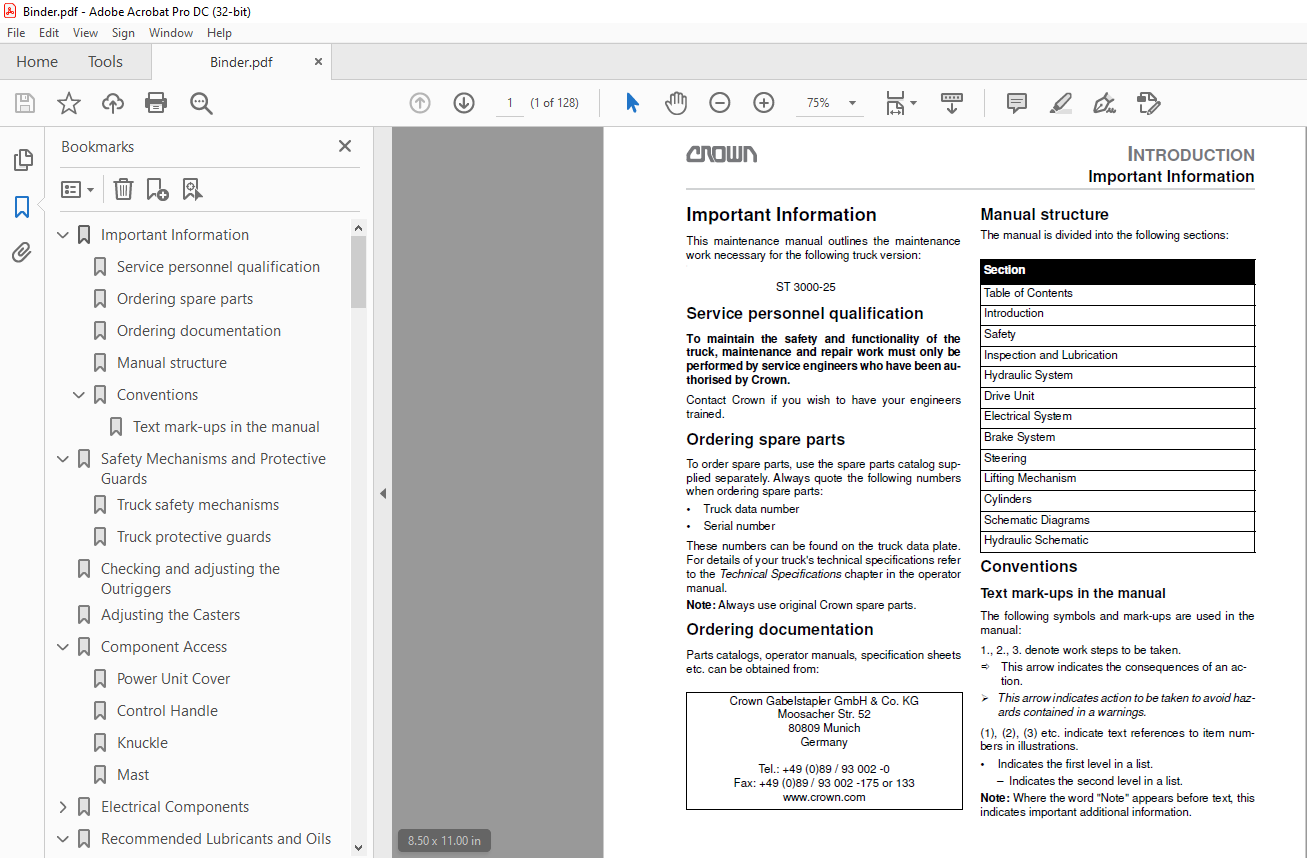
Important Information 1
Service personnel qualification 1
Ordering spare parts 1
Ordering documentation 1
Manual structure 1
Conventions 1
Text mark-ups in the manual 1
Safety Mechanisms and Protective Guards 3
Truck safety mechanisms 3
Truck protective guards 3
Checking and adjusting the Outriggers 5
Adjusting the Casters 6
Component Access 7
Power Unit Cover 7
Control Handle 7
Knuckle 7
Mast 7
Electrical Components 9
Traction Pod (POT, FS, RS) 9
Fast / Slow Travel Switch (HSS) 9
Safety Reverse Switch (SAS) 9
Brake Switch (BRS) 9
Override Switch (ORS) 9
Raise / Lower Switches (RAS, LOS) 9
Limit Switch (LMS) 9
Horn Switch (HNS) 10
Key Switch (KYS) 10
Emergency Disconnect (BD) 10
Fuses (FU) 10
Thermal Switch (THS) 10
Hydraulic Control Module (HCM) 10
Unigage (BDI) 10
Integrated Charger 10
Plug Holder (PC) 10
Drive motor (M1) 10
Pump Motor (M2) 10
Main Contactor (Line/LC) 10
Lift Contactor (P/P1+P2) 10
Electromagnetic Brake (BRK) 10
Terminal Board (TB) 10
Travel Alarm Driver (DR) 10
Aux Hydraulic Switch (SLS/SRS) 11
Remote Control Toggle Switch (ECS) 11
Aux Hydraulic Valves (SVA1/SVA2) 11
Horn (HN) 11
Main Circuit Board (MAIN PCB) 11
Hydraulic Circuit Board (HYD PCB) 11
Travel Alarm (ALM) 11
Receiver 11
Transmitter 11
Recommended Lubricants and Oils 15
Lubricants 15
Cold Store Trucks 15
Truck Decommissioning 15
Restoring the Truck to Service 15
Planned Maintenance 17
Lubrication points and intervals 18
Inspection and Maintenance Schedule 20
Operation 29
Raise 29
Lower 30
General Rules for Hydraulic Lines and Fittings 31
Hydraulic Unit 32
Hydraulic reservoir capacity 32
Changing the hydraulic oil and hydraulic filter 32
Maintaining the Hydraulic Unit 34
Removing the hydraulic unit 35
Maintaining the pump motor 35
Maintaining the pump 35
Installing the hydraulic unit 35
Replacing and Adjusting the Relief Valve 36
Troubleshooting 37
Gear Unit Overview 39
Removing and Installing the Drive Unit 40
Drive unit removal 40
Drive unit installation 40
Drive motor 41
Removing the drive motor 41
Disassembling the drive motor 41
Assembling the drive motor 41
Fitting the drive motor to the gear unit 41
Gear Unit Disassembly and Assembly 45
Disassembling the gear unit 46
Assembling the gear unit 46
Installing the gear unit cover 49
Drive unit installation 49
SEM0 Traction Controller 51
General 51
Precautionary Measures 51
Functional Characteristics 51
Speed control 51
Reduced speed ranges 51
Downhill speed control 51
Regenerative braking 51
Anti Roll Down Function 51
Hourmeter 52
Self-Diagnostic System 52
Monitored Circuits 52
Safety Mechanisms 52
Incorrect polarity 52
Wiring Errors 52
Temperature protection 52
Start sequence 52
Protection rating 52
Controller Maintenance 53
Replacing and Setting Up the SEM0 Traction Controller 54
Replacing the controller 54
Parameter Setting 54
Status LED 56
Programmer 57
General 57
Operating SEM0 Controller Menu 58
General 58
Menu structure 58
Menu Functions 59
PARAMETER CHANGE 59
TEST 59
ALARMS 59
PROGRAM VACC 59
CONFIG 59
Functions Menu, general 60
Parameter Change Menus 61
Settings and Error Messages 62
Tester Menu 63
TESTER Menu 64
Alarms Menu 65
Calibrating the Traction Potentiometer, PROGRAM VACC menu 69
Preparatory Measures 69
Calibration 69
CONFIG Menu 70
SET OPTIONS, ADJUSTMENTS and SET MODEL sub-menus 71
SET MODEL 71
SET OPTIONS 71
ADJUSTMENTS 71
On Board Battery Charger 73
To set the battery tpye at the On Board Battery Charger 73
Calibrating the Hydraulic Control Module (HCM) 75
Battery Discharge Indicator (BDI) 77
OPERATION 77
General 77
Battery Discharge Indicator Setting (BDI) 79
Calibration for wet batteries 79
Traction Controller Safety Test 81
General 81
Required tools 81
PMT Test 81
Pump Motor Maintenance 83
Maintaining the brushes 83
Disassembly 83
Inspection 83
Assembly 83
Traction Motor Maintenance 85
Accessing the brushes 85
Maintenance 85
Armature 85
Bearings 85
Brake 87
Brake Function 87
Brake disassembly 87
Brake assembly 88
Air gap setting 88
Brake moment setting 89
Brake test 89
Definition of run-in/new rotor 89
General Notes 90
Trobleshooting 91
Live ring bearing 93
Disassembly 93
Assembly 93
Mast 95
General 95
Torque Requirements 95
Lifting Gear Minimum Capacity 95
TL Mast 95
TT Mast 95
Mast Removal 95
Installation 96
Fork Carriage Removal 96
Fork Carriage Installation 96
Fork Carriage Adjustment 97
Mast Maintenance 99
Lubricating the roller tracks 99
TL Mast Assembly100
TT Mast Assembly101
General103
Safety when working on hydraulic systems103
General Instructions for Repairing Hydraulic Components103
Mast Lift Cylinder Repair104
Seal Replacement104
Removing the mast lift cylinder104
Disassembling the mast lift cylinder104
Assembling the mast lift cylinder105
Installing the mast lift cylinder105
Free Lift Cylinder Repair106
Seal Replacement106
Removing the free lift cylinder106
Disassembling the free lift cylinder106
Assembling the free lift cylinder107
Installing the free lift cylinder107
Cylinder Bleeding and Flushing108
Bleeding — Mast Lift Cylinders108
Flushing – Mast Lift Cylinders and Free Lift Cylinder (if applicable)108
Drift Test109
Cylinder Shimming110
Free lift cylinder shimming110
Mast lift cylinder shimming110
Overview Schematic (Standard, without Options)111
Traction Controller SEM0, Logic Side112
Traction Controller SEM0, Power Side113
Power Unit Control Circuit114
Control Handle Circuit115
Hydraulic Control Modul (HCM)116
Overview Schematic (with Options)117
Traction Controller SEM0, Logic Side118
Traction Controller SEM0, Power Side119
Power Unit Control Circuit120
Control Handle Circuit121
Hydraulic Control Module (HCM) – Travel Alarm and Flashing Beacon122
Remote Control Power Unit123
Remote Control Operator Platform124
InfoLink® Pinout125
Hydraulic Circuit ST 3000-25127
IMAGES PREVIEW OF THE MANUAL:
More products