$43
Crown Forklift TSP 7000 Series Service Manual – PDF DOWNLOAD
Crown Forklift TSP 7000 Series Service Manual – PDF DOWNLOAD
FILE DETAILS:
Crown Forklift TSP 7000 Series Service Manual – PDF DOWNLOAD
Language : English
Pages :816
Downloadable : Yes
File Type : PDF
DESCRIPTION:
Crown Forklift TSP 7000 Series Service Manual – PDF DOWNLOAD
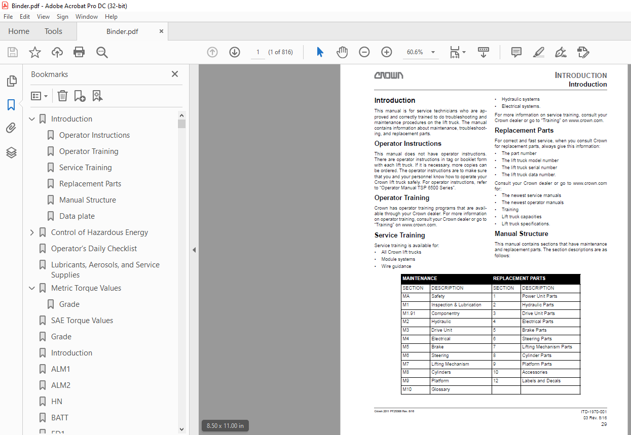
Introduction
This manual is for service technicians who are approved
and correctly trained to do troubleshooting and
maintenance procedures on the lift truck. The manual
contains information about maintenance, troubleshooting,
and replacement parts.
Operator Instructions
This manual does not have operator instructions.
There are operator instructions in tag or booklet form
with each lift truck. If it is necessary, more copies can
be ordered. The operator instructions are to make sure
that you and your personnel know how to operate your
Crown lift truck safely. For operator instructions, refer
to “Operator Manual TSP 6500 Series”.
TABLE OF CONTENTS:
Crown Forklift TSP 7000 Series Service Manual – PDF DOWNLOAD
Introduction 1
Operator Instructions 1
Operator Training 1
Service Training 1
Replacement Parts 1
Manual Structure 1
Data plate 2
Control of Hazardous Energy 0
Lockout/Tagout 0
Battery 0
Safety Rules 0
Battery Maintenance 0
Only personnel that have experience with batteries can do maintenance and repair on batteries 0
Battery Charging 0
Do not smoke or use a flame near the battery Gas made while you charge a battery is very explosive and can cause injury 0
Battery Removal 0
When you remove the battery, move the truck to an area that is used for battery maintenance The floor must be flat Lower the mast(s) fully, turn the truck OFF, and remove the key Disconnect the battery and lockout/tagout the truck (refer to SAFETY 0
Fig 1 (8251) 0
Battery Installation 0
Turn the truck OFF and remove the key If the battery was removed with the mast(s) raised, use a lift attached to the mast to supply tip over protection Do not metal objects to touch the top of the battery cells This may cause a short circuit when 0
Make sure the battery that you use agrees to the weight, capacity, amperage, and voltage requirements of the truck (refer to serial plate) NEVER operate the truck with a battery that does not agree with the requirements 0
Lockout/Tagout 0
Fig 2 (12723) 0
Capacitance 0
1 Move the truck to a maintenance area that has a flat and level floor 0
2 Turn the truck OFF and remove the key 0
3 Lockout/tagout the truck Refer to SAFETY>Control of Hazardous Energy>Lockout/Tagout 0
4 Wait for 2 minutes after you disconnect the battery for the capacitors to release 0
5 To make sure that the capacitors are released, put a volt-meter across the B+ and B- terminals of the ACCESS 2 and ACCESS 3 modules 0
Fig 3 (26141) 0
Hydraulic 0
AVOID HIGH PRESSURE FLUIDS 0
• High pressure fluid can go through the skin and cause serious injury 0
• Release the pressure before you disconnect the hydraulic lines 0
• Tighten all connections before you apply the pressure 0
• Keep your hands and body away from pin holes which eject high pressure fluids 0
• Use a piece of cardboard or paper to examine for leaks Do not use your hand 0
• High pressure fluid that goes into the skin can become a severe medical emergency even when the skin looks normal 0
• There is a delayed start of pain, and severe tissue damage may occur 0
• You must get medical aid from a specialist who has had experience with this type of injury 0
Fig 4 (26021) 0
Releasing the Brakes 0
To release the brakes through the Access 123 UTILITIES Menu 0
1 Lower the mast(s) fully 0
2 Lockout/tagout the truck Refer to SAFETY>Control of Hazardous Energy>Lockout/Tagout 0
3 Put chocks against the wheels of the truck to prevent unwanted movement of the truck when the brakes are released 0
4 When you tow the truck, make sure that the operator knows of the procedures to apply the brakes 0
5 Connect the battery and start the truck in the “Service” mode of ACCESS 1 and put in the password 0
6 Scroll the display of ACCESS 1 using the down arrow to the “UTILITIES” Menu and push the ENTER key 0
7 Use the up/down arrows to scroll to U2 “Active Tow Mode” and push the ENTER key 0
8 The operator can release the brakes at this time by closing the gates and then sit or stand-up with 2 feet on the presence pedals (DMS) and having the right hand on the right Multi-Task Handle 0
When the brakes are released the truck will be free to move 0
9 The truck can be towed and the operator can steer the truck (NOTE: If the operator opens a gate, removes a foot or the right hand, the brakes will apply) 0
10 Move the truck to a maintenance area that has a flat and level floor 0
11 Turn the truck off to disable tow mode 0
To release the brakes using the Drive/Tow Switch (DTS) 0
Use precaution when you use the Drive/Tow Switch (DTS) to release the brakes The truck will be free to move and the brake pedal in the operator compartment will have no effect on the brakes Also, the steering system will not operate The brakes wil 0
1 Lower the mast(s) fully 0
2 Lockout/tagout the truck Refer to SAFETY>Control of Hazardous Energy>Lockout/Tagout 0
3 Put chocks against the wheels of the truck to prevent unwanted movement of the truck when the brakes are released 0
4 When you tow the truck, make sure that all the operators and other personnel know the trucks brakes do not operate correctly 0
5 Disconnect the brake harness from the primary harness at connector PC407 and connect the brake harness to the distribution panel at CA203 0
6 Connect the battery and move the Drive/Tow Switch (DTS) from the Drive position to the Tow position 0
7 Remove the wheel chocks and move the truck to a level area that is used for maintenance 0
8 Move the Drive/Tow Switch (DTS) from the Tow position to the Drive position 0
9 Disconnect the battery 0
10 Disconnect the brake harness from the distribution panel and connect the brake harness to its first connection, CA407 0
Fig 5 (17675) 0
To release the brakes mechanically 0
Be careful when you use the manual brake procedure to release the brake The truck will be free to move and the brake pedal in the operator compartment will have no effect on the brakes With the truck OFF, the truck will not have traction or steerin 0
1 Lower the mast(s) fully 0
2 Lockout/tagout the truck Refer to SAFETY>Control of Hazardous Energy>Lockout/Tagout 0
3 Put chocks against the wheels of the truck to prevent unwanted movement of the truck when the brakes are released 0
4 Use a wrench, a punch or a screwdriver to turn the torque adjuster plate This will remove the spring preload 0
5 Remove the wheel chocks and move the truck to a maintenance area When you tow the truck, make sure all the operators and other personnel are told of the problem with the truck’s brake operation and steering Refer to SAFETY>Control of Hazardous E 0
6 To reapply the brake, turn the torque adjuster plate back to its first position to get the correct spring load 0
The truck will not have braking if you do not put the adjuster plate in its original position 0
7 Put a thin layer of lubricant on the top surface of the adjuster plate to decrease the likelihood of bending the compression springs 0
8 Refer to Torque Gap Adjustment in the Brake section of this manual for the factory adjustments 0
Towing the Truck 0
Towing by Pulling in Power Unit First Direction 0
• The towed truck must always have 3 points touching the floor and/or the towing device 0
• The maximum travel speed while you tow the truck is 16 km/h (1 mph) 0
• Do not make sharp turns when you lift and tow this truck 0
• The floor must be flat, level, and clean 0
Fig 6 (26147) 0
Towing by Pushing in Forks First Direction 0
• The towed truck must always have 3 points touching the floor and/or the towing device 0
• The maximum travel speed while you tow the truck is 16 km/h (1 mph) 0
• Do not make sharp turns when you lift and tow this truck 0
• The floor must be flat, level, and clean 0
Fig 7 (26148) 0
Jacking and Blocking 0
1 Move the truck to a maintenance area that has a flat and level floor 0
2 No load on forks 0
3 Lockout/tagout the truck Refer to SAFETY>Control of Hazardous Energy>Lockout/Tagout 0
4 To lift the mainframe, refer to Figure 8 To lift the power unit, refer to Figure 9 0
Fig 8 (26149) 0
Fig 9 (26150) 0
5 Put chocks against the load wheels if the power unit is being lifted 0
6 Put the hydraulic jack in the cutout of the component being lifted 0
Do not raise the operator platform component more than 450 mm (18 in) from the floor 0
Truck stability decreases dramatically if the load wheels are raised more than 13 mm (05 in) 0
Do not put hardwood blocks at the back of the power unit between the jack notches Doing so can result in damage to the guidance sensor 0
7 Use the hydraulic jack and lift the truck enough to put a hardwood block below the mainframe or the power unit Then lower the truck onto the hardwood block 0
Fig 10 (26151) 0
Main Mast – TF & TN 0
1 Move the truck to a maintenance area that has a flat and level floor 0
2 Put chocks against the wheels of the truck to prevent movement of the truck Refer to SAFETY>Control of Hazardous Energy>Jacking and Blocking 0
3 Connect the battery 0
4 Raise the main mast to get the necessary second stage height and then put the applicable length blocks in each mainframe rail 0
5 Hold the blocks on the mainframe with a strap or clamp 0
6 Lower the mast onto the blocks and make sure the platform is against the stops 0
7 Lockout/tagout the truck Refer to SAFETY>Control of Hazardous Energy>Lockout/Tagout 0
Fig 11 (26276) 0
Main Mast – TT 0
1 Move the truck to a maintenance area that has a flat and level floor 0
2 Put chocks against the wheels of the truck to prevent movement of the truck Refer to SAFETY>Control of Hazardous Energy>Jacking and Blocking 0
3 Connect the battery 0
4 Remove the screw and nut from one end of the locking tube tool and put the tool through the first stage mast Then install the screw and nut back through the locking tube tool to secure it in position 0
5 Lower the mast until the second stage is on the locking tube tool and the platform is fully lowered 0
6 Lockout/tagout the truck Refer to SAFETY>Control of Hazardous Energy>Lockout/Tagout 0
Fig 12 (20176) 0
Blocking Third Stage Mast Above Second Stage Mast 0
1 Move the truck to a maintenance area that has a flat and level floor 0
2 Put chocks against the wheels of the truck to prevent movement of the truck Refer to SAFETY>Control of Hazardous Energy>Jacking and Blocking 0
3 Connect the battery 0
4 Refer to Figure 13 Raise the mast until there is a sufficient distance to install the two 100 x 75 x 355 mm (4 x 3 x 14 in) hardwood blocks into the second stage mast rails (I-beams) and the two 100 x 75 x 1219 mm (4 x 3 x 48 in) hardwood blocks 0
5 Refer to Figure 13 Attach the hardwood blocks to the mast rails with clamps or straps 0
Fig 13 (26153) 0
6 Refer to Figure 13 Lower the mast so the third stage mast is on the two 355 mm (14 in) long blocks and the platform is on the two 1219 mm (48 in) long blocks 0
7 Lockout/tagout the truck Refer to SAFETY>Control of Hazardous Energy>Lockout/Tagout 0
Auxiliary Mast 0
1 Move the truck to a maintenance area that has a flat and level floor 0
2 Put chocks against the wheels of the truck to prevent movement of the truck Refer to SAFETY>Control of Hazardous Energy>Jacking and Blocking 0
3 Connect the battery 0
4 Raise the fork carriage to get the correct height and then put the correct length blocks in each of the mast rails 0
5 Hold the hardwood blocks on the mast rails with a strap or clamp 0
6 Lower the fork carriage so the carriage is on the blocks 0
7 Lockout/tagout the truck Refer to SAFETY>Control of Hazardous Energy>Lockout/Tagout 0
Fig 14 (26277) 0
Platform – TT 0
1 Move the truck to a maintenance area that has a flat and level floor 0
2 Put chocks against the wheels of the truck to prevent movement of the truck Refer to SAFETY>Control of Hazardous Energy>Jacking and Blocking 0
3 Connect the battery 0
4 Raise the platform enough in free lift to put the jack stands or hardwood blocks in the channels of the mast 0
5 Lower the platform onto the jack stands or hardwood blocks 0
6 Lockout/tagout the truck Refer to SAFETY>Control of Hazardous Energy>Lockout/Tagout 0
Fig 15 (20178) 0
Height Sensor 0
The spring is reverse wound and if it is not kept restrained, it will unwind fully and then wind in the opposite direction Personal injury is possible if you do not use extreme caution It is recommended to wear safety glasses and gloves when you re 0
Tool Fabrication 0
Fig 16 (17667) 0
Spring Removal 0
1 Remove the height sensor from the truck and lock the sensor in a vice 0
When you remove the last screw, turn the cover approximately 5 revolutions to release the spring force 0
2 Remove the four screws from the reel cover and let the spring force release through cover rotation 0
3 Pull the cover approximately 254 mm (10 in) from the housing Then, using a screwdriver, slowly remove the arbor off the square shaft of the cover 0
4 Remove the cover from the spacer Remove the grease 0
5 Carefully pull the arbor from the spring using a needle nose pliers 0
6 Move the opening in the inner spacer around until you have access to the spring retainer screws 0
7 Remove the spring retainer screws 0
The spring is reverse wound and if it is not kept restrained, it will unwind fully and then wind in the opposite direction Personal injury is possible if you do not use extreme caution It is recommended to wear safety glasses and gloves when you re 0
8 Use a fabricated rod or screwdriver, start to remove the spring approximately 127 mm (05 in) out of the reel 0
Fig 17 (17680) 0
9 Hold the spring with locking pliers near the end of the spring on the outside diameter While you hold the locking pliers with one hand, remove the spring from the reel with the fabricated tool 0
Fig 18 (17681) 0
10 Carefully put cable ties around the spring so the locking pliers can be removed Discard the spring 0
Spring Installation 0
1 When the height sensor is ready to have the spring installed, put a locking pliers carefully on the reel shaft and secure the locking pliers to keep the reel from turning Put a bolt through the reel housing to lock the reel 0
Fig 19 (17636) 0
2 The new spring is shipped with a rod wrapped partially around the circumference of the spring and is tied with cable ties Make sure the rod is in the center of the spring and then remove the cable ties 0
3 Move the shipping rod around the circumference of the spring so the end of the spring extends out between the ends of the rod 0
4 Assemble the hook of the spring retainer in the hole of the spring The retainer mounting tab must be on the opposite side of the spring as the diagonally cut corner at the end of the spring 0
5 Put the inner spacer between the spring and the spring retainer so the raised portion of the spacer is away from the spring 0
6 Put the assembly into the reel, spring retainer first, and work the shipping bar to the outer edge of the spring Move the assembly around until the holes in the spring retainer and reel align Start the screws to hold the spring retainer to the reel 0
7 Carefully push the spring into the reel and let it expand in the reel Tighten the screws holding the spring retainer 0
8 Fully soak the spring with lubricant 063001-009 Use lubricant 063002-059 for trucks used for operation in a freezer 0
9 Put the arbor into the center of the spring so when the arbor is turned clockwise, the flat on the arbor pulls the spring 0
10 Put a layer of lubricant (063001-009) on the surfaces of the end spacer and position it in the reel housing 0
11 Put the square shaft of the cover into the arbor and put the cover against the housing Turn the cover clockwise five revolutions Then put the screws in and tighten them 0
Platform and Load Handler Lifting 0
Load Handler 0
1 Move the truck to a maintenance area that has a flat and level floor 0
2 Lower the main and auxiliary masts fully No load on forks 0
3 Lockout/tagout the truck Refer to SAFETY>Control of Hazardous Energy>Lockout/Tagout 0
4 Put chocks against the wheels of the truck to prevent movement of the truck Refer to SAFETY>Control of Hazardous Energy>Jacking and Blocking 0
5 Remove the top and bottom traverse stop blocks from the left end of the top and bottom traverse gear racks 0
6 Put the display in “Shipping Mode” 0
7 Connect a lift to the auxiliary mast and raise the load handler enough to move the load handler weight from the platform to the lift 0
8 Slowly power the load handler off the left end of the traverse gear racks by requesting “traverse left” using the thumb ball on the right multi-task handle Use precaution to prevent damage to the gang hose and load handler wire harness 0
9 Disconnect the load handler wire harness 0
10 Disconnect the hoses and seal the hose ends to prevent hydraulic system contamination 0
11 Carefully move the load handler away from the truck 0
Platform 0
1 Move the truck to a maintenance area that has a flat and level floor 0
2 Lower all the masts fully No load on forks 0
3 Lockout/tagout the truck Refer to SAFETY>Control of Hazardous Energy>Lockout/Tagout 0
4 Put chocks against the wheels of the truck to prevent movement of the truck Refer to SAFETY>Control of Hazardous Energy>Jacking and Blocking 0
5 Remove the load handler 0
6 Remove the spotlights and overhead fan from the overhead guard, if applicable 0
7 Put a 100 x 100 mm (4 x 4 in) hardwood block below the overhead guard, tight against the back of the platform Make sure the hardwood block is a minimum of 305 mm (120 in) longer than the overhead guard and is on center8 Use a 3-point hook-up and attach a strap, chain, etc to the hardwood block and the back of the overhead guard Raise the platform to the necessary height 0
9 Block or remove the platform Refer to PLATFORM>Platform>Removing the Platform for procedures to remove the platform 0
Fig 20 (17670) 0
Operator’s Daily Checklist 27
Lubricants, Aerosols, and Service Supplies 0
Metric Torque Values 48
Grade 48
SAE Torque Values 52
Grade 52
Introduction 0
Hydraulic System119
General Information119
Hydraulic Plumbing and Fittings120
Reservoir and Filters120
Drift Tests122
Hydraulic Circuits123
Lift Circuit123
Lower Circuit124
Lower Circuit (MVL)125
Load Handler Circuit through the Mainframe Manifold Block126
Mainframe Manifold Auxiliary Circuit:126
Auxiliary Lift Circuit127
Auxiliary Lower Circuit128
Traverse Left Circuit129
Traverse Right Circuit130
Fork Extend Circuit132
Fork Retract Circuit134
Pivot Right Circuit136
Pivot Left Circuit138
Hydraulic Schematic Symbols141
Manifolds148
Relief Valve (RV1)148
Manifold Block O-Ring Replacement148
Preparation Before Disassembly 0
Tools and Materials Required for Servicing 0
Reassembly 0
Final Checks 0
Traverse Motor170
Prepare the Traction Motor for Disassembly170
Traverse Motor Disassembly171
Traverse Motor Assembly178
Troubleshooting185
Drive Unit186
Drive Tire Replacement186
Changing the Oil187
Drive Unit Removal188
Drive Unit Installation189
Traction Motor Removal189
Traction Motor Installation189
Encoders190
Operation190
Wire designations190
Testing the encoders190
Channel feedback overview190
Index voltage overview191
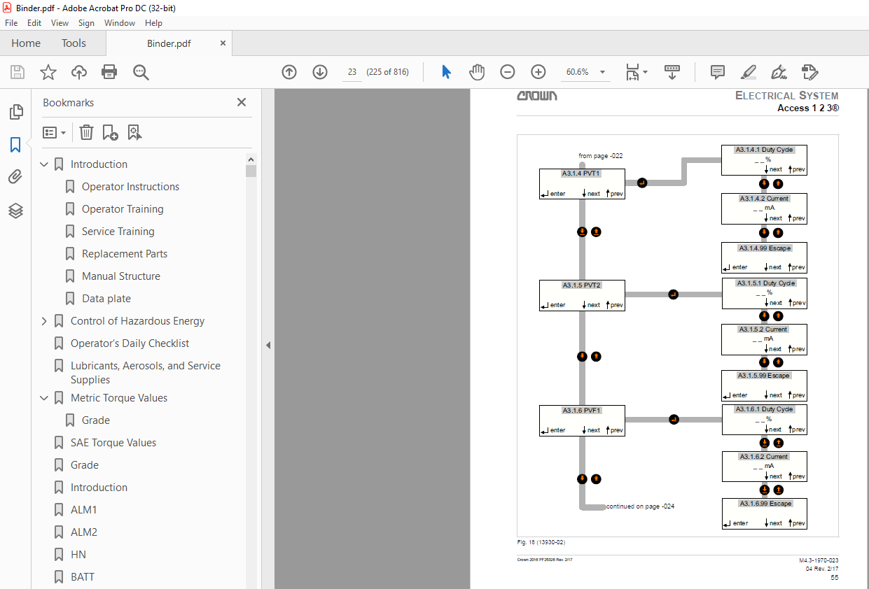
Access 1 2 3®203
Static Return to Off (SRO)203
Access 1 2 3® Menus203
User Codes204
Message Mode205
HOUR METERS Menu Description206
EVENT CODES Menu Description206
LEVEL 2 and LEVEL 3 Menu Description207
ANALYZER301
FEATURES Menus326
PERFORMANCE Menus345
PERFORMANCE Menu Overview345
CALIBRATION360
HOUR METERS377
EVENT CODES379
UTILITIES381
Guidance System384
Operation of the Wire Guidance System384
Steer Modes385
Sensors387
Line Driver Output387
Calibration389
Troubleshooting389
Contactors397
Emergency Disconnect Contactor (ED1)397
Contact Replacement398
Coil Replacement399
Logic Power Contactors (K2 & K3)399
Battery401
Safety Procedures402
Battery Inspection402
Battery Charging402
Battery Removal404
Battery Installation404
Battery Load Test405
Motors407
Event Codes408
Access Module Listing:408
Event Code 101409
Event Code 104410
Event Code 105411
Event Code 106412
Event Code 107413
Event Code 108413
Event Code 112414
Event Code 113414
Event Code 114414
Event Code 115414
Event Code 116414
Event Code 117414
Event Code 118415
Event Code 119415
Event Code 122415
Event Code 123415
Event Code 125415
Event Code 150415
Event Code 191416
Event Code 194416
Event Code 195416
Event Code 196416
Event Code 197416
Event Code 198416
Event Code 212416
Event Code 213417
Event Code 214417
Event Code 215417
Event Code 216417
Event Code 217418
Event Code 218418
Event Code 222418
Event Code 223418
Event Code 224419
Event Code 225419
Event Code 228420
Event Code 229420
Event Code 231420
Event Code 232421
Event Code 233422
Event Code 234424
Event Code 235425
Event Code 236426
Event Code 237426
Event Code 238427
Event Code 246427
Event Code 247427
Event Code 249427
Event Code 251427
Event Code 253427
Event Code 254427
Event Code 255428
Event Code 256428
Event Code 268428
Event Code 269428
Event Code 272429
Event Code 273429
Event Code 278430
Event Code 289430
Event Code 293430
Event Code 298430
Event Code 300430
Event Code 312431
Event Code 313431
Event Code 315431
Event Code 317431
Event Code 322432
Event Code 323433
Event Code 325433
Event Code 326434
Event Code 327434
Event Code 328435
Event Code 329435
Event Code 331435
Event Code 332436
Event Code 333436
Event Code 334437
Event Code 336437
Event Code 337438
Event Code 346438
Event Code 347438
Event Code 349438
Event Code 351438
Event Code 368438
Event Code 369439
Event Code 372439
Event Code 373440
Event Code 378440
Event Code 400440
Event Code 402441
Event Code 403442
Event Code 406443
Event Code 407443
Event Code 408444
Event Code 410445
Event Code 411445
Event Code 436446
Event Code 437446
Event Code 438446
Event Code 439447
Event Code 440447
Event Code 441448
Event Code 442448
Event Code 443449
Event Code 444449
Event Code 445449
Event Code 446450
Event Code 447451
Event Code 491451
Event Code 501451
Event Code 502452
Event Code 503453
Event Code 504453
Event Code 505454
Event Code 507454
Event Code 508455
Event Code 509455
Event Code 511456
Event Code 522456
Event Code 524457
Event Code 526457
Event Code 528458
Event Code 530458
Event Code 532459
Event Code 534459
Event Code 536460
Event Code 537460
Event Code 538461
Event Code 540461
Event Code 541462
Event Code 542463
Event Code 543463
Event Code 544464
Event Code 545464
Event Code 546464
Event Code 551465
Event Code 552465
Event Code 554465
Event Code 555465
Event Code 557466
Event Code 558466
Event Code 562467
Event Code 563468
Event Code 564468
Event Code 565468
Event Code 566469
Event Code 567469
Event Code 571469
Event Code 576470
Event Code 582470
Event Code 586471
Event Code 588472
Event Code 590473
Event Code 592473
Event Code 598473
Event Code 605474
Event Code 611474
Event Code 631474
Event Code 632474
Event Code 633475
Event Code 636476
Event Code 637476
Event Code 638476
Event Code 652477
Event Code 660478
Event Code 664478
Event Code 668478
Event Code 672478
Event Code 681479
Event Code 682479
Event Code 683479
Event Code 684479
Event Code 685480
Event Code 686480
Event Code 687480
Event Code 688480
Event Code 689480
Event Code 690481
Event Code 691481
Event Code 692481
Event Code 693481
Event Code 694481
Event Code 695481
Event Code 696482
Event Code 697482
Event Code 698482
Event Code 700483
Event Code 701484
Event Code 702485
Event Code 707486
Event Code 708487
Event Code 711488
Event Code 736488
Event Code 737488
Event Code 738489
Event Code 739489
Event Code 740490
Event Code 741490
Event Code 742491
Event Code 743491
Event Code 744492
Event Code 745492
Event Code 746493
Event Code 747494
Event Code 750494
Event Code 751495
Event Code 752496
Event Code 753496
Event Code 754497
Event Code 755498
Event Code 756498
Event Code 757499
Event Code 758500
Event Code 759500
Event Code 760501
Event Code 761501
Event Code 762502
Event Code 763502
Event Code 764503
Event Code 765503
Event Code 767504
Event Code 768504
Event Code 769505
Event Code 770505
Event Code 771505
Event Code 772506
Event Code 773506
Event Code 774507
Event Code 775507
Event Code 776507
Event Code 777508
Event Code 778509
Event Code 779509
Event Code 780509
Event Code 781510
Event Code 782511
Event Code 783512
Event Code 784512
Event Code 785513
Event Code 790513
Event Code 800513
Event Code 801514
Event Code 802515
Event Code 803516
Event Code 804517
Event Code 805518
Event Code 806519
Event Code 807520
Event Code 816521
Event Code 821521
Event Code 822521
Event Code 823521
Event Code 824522
Event Code 825522
Event Code 836523
Event Code 837523
Event Code 838524
Event Code 839524
Event Code 840525
Event Code 841526
Event Code 842526
Event Code 843526
Event Code 844527
Event Code 845527
Event Code 846527
Event Code 847528
Event Code 848529
Event Code 849531
Event Code 850532
Event Code 853532
Event Code 856533
Event Code 860533
Event Code 864534
Event Code 868534
Event Code 870535
Event Code 872536
Event Code 875537
Event Code 878538
Event Code Introduction540
Brake Force Adjustment 0
Torque Gap Adjustment 0
Air Gap Adjustment 0
Rotor and Brake Pad Replacement 0
Brake Assembly 0
Brake548
Stopping the Truck548
Stopping Distance Adjustment548
Torque Gap Adjustment548
Air Gap Adjustment551
Rotor and Brake Pad Replacement552
To Assemble the Brake554
Steering Gearbox558
Replacing Steering Gearbox558
Steer Motor563
Replacing the Steer Motor Brushes563
Steer Motor Replacement564
Steering Gearbox567
Steering Gearbox Replacement567
Hose Take-Up Cable574
Hose Take-Up Cable Replacement574
Mast 0
TN (Telescopic No Free Lift) Mast 0
TF (Telescopic Full Free Lift) Mast 0
TT (Triple Telescopic Full Free Lift) Mast 0
New Truck Installation Procedures 0
Second Stage Mast Removal and Installation – TF and TN 0
Second and Third Stage Mast Removal – TT 0
Second Stage Mast Installation – TF and TN 0
Second and Third Stage Mast Installation – TT 0
Side Thrust Roller Adjustment – TF, TN, and TT 0
Lift Chains614
Inspection614
Wear614
Corrosion615
Plates with Cracks615
Tight Joints616
Turned Pins616
Lift Chain Side Wear616
Lift Chain Lubrication617
Lift Chain Replacement617
Chain Leaf Disconnect617
Fork Inspection620
Abrasion620
Blade Measurement620
Hanger Bore Measurement621
Overloading623
Fatigue623
Bent or Twisted Forks623
Hanger624
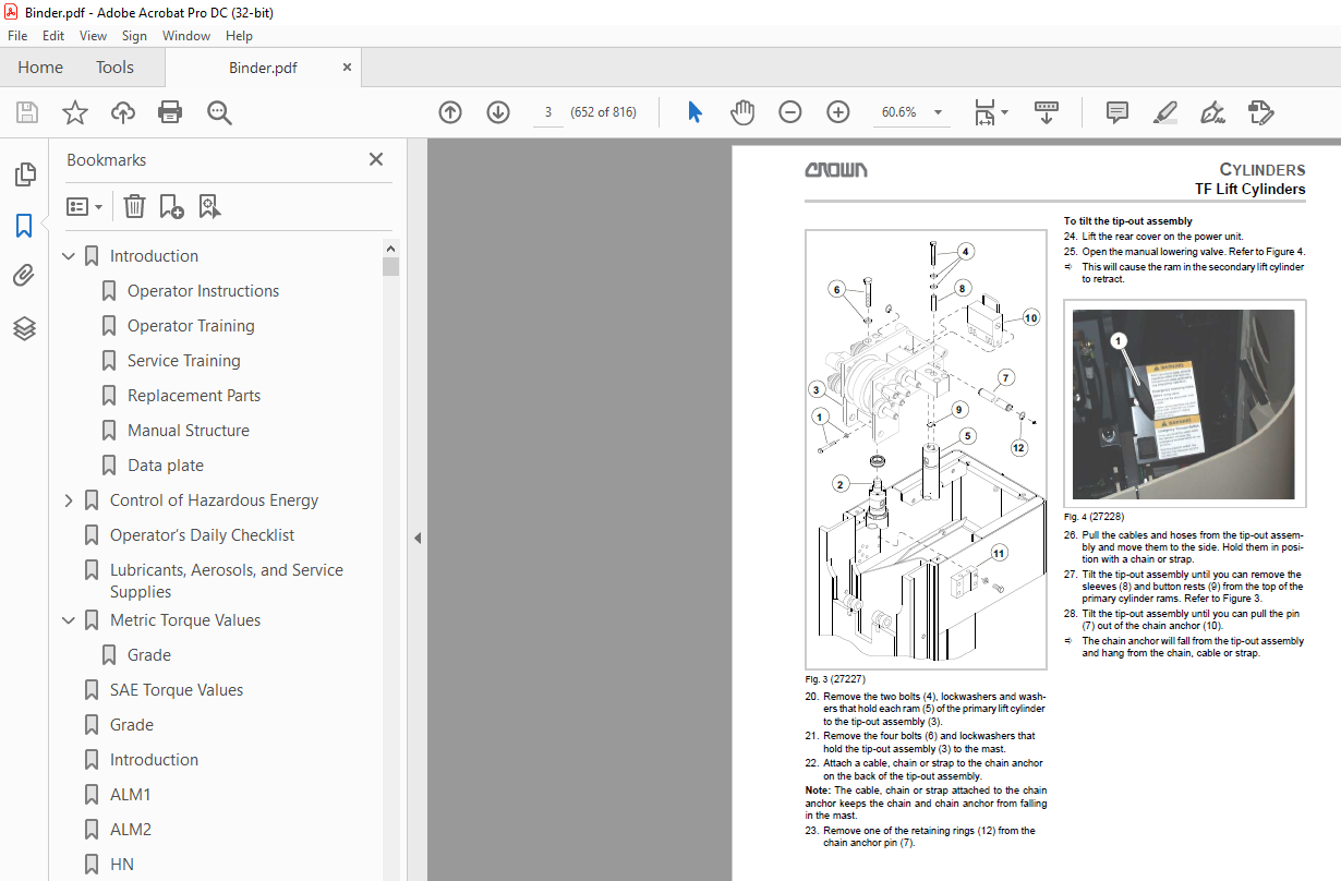
Pivoting The Tip-Out Assembly 0
Primary (Free) Lift Cylinder Repair 0
Cylinder Packing Installation 0
Reassembling Mast Tip-Out 0
Primary (Free) Lift Cylinder Removal 0
Secondary (Main) Lift Cylinder Removal 0
Primary (Free) Lift Cylinder Installation 0
Secondary (Main) Lift Cylinder Installation 0
Lift Cylinder Bleeding 0
Auxiliary Lift Cylinder Repair 0
Rod Packing Installation 0
Auxiliary Lift Cylinder Bleeding 0
Cylinder Disassembly 0
Piston Rod Disassembly 0
Cylinder Reassembly 0
Access to the Lift Cylinders650
To Replace the Seals in the PrimaryLift Cylinder653
Primary Lift Cylinder Removal656
Primary Lift Cylinder Installation657
Secondary Lift Cylinder Removal657
Secondary Lift Cylinder Installation658
To Bleed the Lift Cylinders659
Pivoting The Tip-Out Assembly 0
Lift Cylinder Repair 0
Cylinder Packing Installation 0
Reassembling Mast Tip-Out 0
Lift Cylinder Removal 0
Lift Cylinder Installation 0
Lift Cylinder Bleeding 0
Cylinder Removal 0
Cylinder Disassembly 0
Cylinder Reassembly 0
Cylinder Installation 0
Pivot Cylinder Bleeding 0
Access to the Lift Cylinder673
To Replace the Seals in the Lift Cylinder675
Lift Cylinder Removal678
Lift Cylinder Installation678
To Bleed the Lift Cylinders679
Pivot Cylinders695
General Information695
Basic Troubleshooting695
Pivot Cylinder Removal696
Pivot Cylinder Disassembly696
Assemble the Pivot Cylinder698
Pivot Cylinder Installation699
Pivot Cylinders Bleeding699
Inspection and Adjustment701
Lubrication702
Mast Shield702
Gates703
GTSL & GTSR704
Chain Anchor and Platform Height Adjustment704
Side Thrust Roller Adjustment – Platform (TF, TN and TT Mast)704
Traverse Hose Replacement705
Platform Removal706
Platform Assembly709
Seat Pivot Bearing Assembly710
Seat Rotate Switch Adjustment710
Seat Power Cable Installation711
Seat Up/Down Switch Adjustment712
Mirror Installation713
Mirror Adjustment715
Inspection and Adjustment 0
Lubrication 0
Mast Shield 0
Gates 0
GTSL & GTSR 0
Chain Anchor and Platform Height Adjustment 0
Side Thrust Roller Adjustment – Platform (TF, TN and TT Mast) 0
Traverse Hose Replacement 0
Platform Removal 0
Platform Assembly 0
Height Sensor Assembly – ECR5734
Height Sensor Assembly Removal734
Height Sensor Assembly Installation735
Height Sense Encoder (ECR5) Replacement736
Cable Replacement736
Height Sensor Assembly – ECR5738
Height Sensor Assembly Removal738
Height Sensor Assembly Installation739
Height Sense Encoder (ECR5) Replacement740
Cable Replacement740
Hydraulic Schematic813
IMAGES PREVIEW OF THE MANUAL:
More products