$44
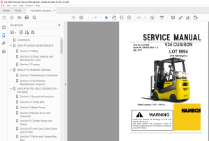
Crown Forklift V34 PNEUMATIC LOT 9994 [ PSI 4G63 Engine] Service Manual - PDF DOWNLOAD
Crown Forklift V34 PNEUMATIC LOT 9994 [ PSI 4G63 Engine] Service Manual - PDF DOWNLOAD
FILE DETAILS:
Crown Forklift V34 PNEUMATIC LOT 9994 [ PSI 4G63 Engine] Service Manual - PDF DOWNLOAD
Language : English
Pages :791
Downloadable : Yes
File Type : PDF
TABLE OF CONTENTS:
Crown Forklift V34 PNEUMATIC LOT 9994 [ PSI 4G63 Engine] Service Manual - PDF DOWNLOAD
CONTENTS 3
GROUP SASAFE MAINTENANCE 4
Section 1 Safety 5
Section 2 Lifting, Jacking, and Blocking the Truck 7
Section 3 Towing 13
GROUP PS PERIODIC SERVICE 15
Section 1 Maintenance Schedules 16
Section 2 The Planned Maintenance Program 21
GROUP 00 (PSI 4G63) ENGINE (LPG - PSI 4G63) 31
Section 1 General Information 32
Section 2 Timing Belt 42
Section 3 Water Pump 55
Section 4 Rocker Arms and Camshaft 58
Section 5 Cylinder Head and Valves 64
Section 6 Front Case, Silent Shaft and Oil Pan 72
Section 7 Piston and Connecting Rod 84
Section 8 Crankshaft and Cylinder Block 94
Section 9 Engine Compression Test107
Section 10 Maintenance111
Section 11 LPG Fuel System118
Section 12 Gasoline Fuel System125
Section 13 Emissions Control System129
Section 14 Electrical Section145
Section 15 Diagnostic Service Tool (DST)148
Section 16 Engine Wire Harness Repair170
Section 17 Diagnostic Trouble Code (DTC)174
GROUP 01 ENGINE COOLING SYSTEM428
Section 1 Engine Cooling System Specifications and Description429
Section 2 Engine Cooling System Troubleshooting430
Section 3 Engine Cooling System Testing and Maintenance431
Section 4 Engine Cooling System and Alternator Belt Service437
Section 5 Radiator Removal and Replacemant441
GROUP 03 INTAKE AND EXHAUST SYSTEM446
Section 1 Intake and Exhaust Systems Specifications and Description447
Section 2 Intake System Troubleshooting448
Section 3 Intake System Service449
Section 4 Exhaust Systems452
GROUP 06 TRANSAXLE (TA12A1 TRANSAXLE)455
Section 1 Transaxle Specifications and Description456
Section 2 Transaxle Disassembly462
Section 3 Transaxle Reassembly470
GROUP 13 ELECTRICAL SYSTEM485
Section 1 Cautions for working on the electrical system486
Section 2 Electrical system Specifications and features487
Section 3 Electrical Circuit Diagram & Electrical Parts Arrangement488
Section 4 Instrument Pod496
Section 5 Electrical Components Specification and Operation521
Section 6 Troubleshooting of Electrical System545
GROUP 22 WHEELS AND TIRES561
Section 1 Wheels and Tires Specifications and Description562
Section 2 Cushion Wheels and Tires563
Section 3 Pneumatic Wheels and Tires566
GROUP 23 BRAKE SYSTEM576
Section 1 Braking / Inching System Specifications and Description577
Section 2 Service Brake Troubleshooting580
Section 3 Brake / Inching Pedals and Linkages Adjustments582
Section 4 Brake System Bleeding585
Section 5 Brake Master Cylinder Service586
Section 6 Service Brake Adjustment and Overhaul589
Section 7 Parking Brake Service595
GROUP 25 STEERING COLUMN AND GEAR597
Section 1 Steering System Specifications and Description598
Section 2 Steering System Troubleshooting600
Section 3 Steering Column and Component Removal and Replacement602
Section 4 Stering System Relief Pressure Check and Adjustment611
Section 5 Steering Gear Overhaul613
GROUP 26 STEER AXLE620
Section 1 Steer Axle Specifications and Description621
Section 2 Steer Axle Wheel Bearing Maintenance and Adjustment623
Section 3 Steer Axle Removal and Replacement627
Section 4 Steer Axle Overhaul631
Section 5 Steer Cylinder Removal and Replacement635
Section 6 Steer Cylinder Overhaul637
GROUP 29 HYDRAULIC SUMP, FILTERS, AND PUMP641
Section 1 Hydraulic Sump, Filters, and Pump Specifications and Description642
Section 2 Main Hydraulic Pump Troubleshooting645
Section 3 Hydraulic Filters and Fluid Maintenance and Change647
Section 4 Hydraulic Pump Removal and Replacement651
Section 5 Hydraulic Pump Overhaul (Jinsung Pump)653
GROUP 30 HYDRAULIC CONTROL VALVE/LIFT CIRCUIT659
Section 1 Hydraulic Control Valve/Lift Circuit Specifications and Description660
Section 2 Hydraulic System Schematics662
Section 3 Hydraulic System Troubleshooting664
Section 4 Hydraulic System Pressure Checks and Adjustments666
Section 5 Hydraulic Control Valve Removal and Replacement671
Section 6 Disassembly and Assembly675
Section 7 Testing of Hydraulic Valve691
GROUP 32 TILT CYLINDERS692
Section 1 Tilt Cylinder Specifications and Description693
Section 2 Tilt Cylinder Checks and Adjustments695
Section 3 Tilt Cylinder Removal and Replacement698
Section 4 Tilt Cylinder Overhaul702
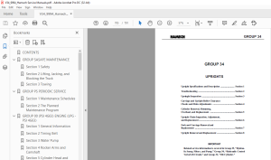
GROUP 34 UPRIGHTS705
Section 1 Upright Specifications and Description706
Section 2 Troubleshooting715
Section 3 Upright Inspection719
Section 4 Carriage and Upright Roller Clearance Checks and Shim Adjustments729
Section 5 Cylinder Removal, Shimming, Overhaul, and Replacement738
Section 6 Upright Chain Inspection, Adjustment, and Replacement744
Section 7 Fork and Carriage Removal and Replacement755
Section 8 Upright Removal and Replacement759
GROUP 38 COUNTERWEIGHT AND CHASSIS763
Section 1 Counterweight Specifications and Description764
Section 2 Counterweight Removal and Replacement765
Section 3 Overhead Guard/Operator’s Cell Removal and Replacement767
Section 4 Floorboard, Cowls, and Seat Deck Removal and Replacement769
Section 5 Operator’s Seat Removal and Replacement773
GROUP 40 SPECIFICATIONS775
Section 1 Nameplates and Decals776
Section 2 General Specifications780
Section 3 Hydraulic Fitting Tightening Procedure790
IMAGES PREVIEW OF THE MANUAL:
S.M 07/24
More products