$40.95
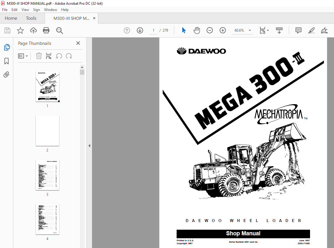
Daewoo Mega 300-III Excavator Shop Manual - PDF DOWNLOAD
Daewoo Mega 300-III Excavator Shop Manual – PDF DOWNLOAD
FILE DETAILS:
Daewoo Mega 300-III Excavator Shop Manual – PDF DOWNLOAD
Language : English
Pages :279
Downloadable : Yes
File Type : PDF
TABLE OF CONTENTS:
Daewoo Mega 300-III Excavator Shop Manual – PDF DOWNLOAD
SAFETY
To the Operator of a Daewoo Wheel Loader 1-1
Basic Wheel Loader Operating Safety 1-1
General Safety Essentials 1-1
Locations of Safety Labels 1-2
Summary of Safety Precautions for Lifting 1-5
Operation 1-7
Equipment 1-10
Maintenance 1-11
Shipping and Transportation 1-13
SPECIFICATIONS
Component Locations 2-1
General Specifications 2-2
Excavator Engine Specifications 2-3
Engine Performance Curves 2-4
Working Range and Dimensions 2-5
Working Capacities 2-7
Approximate Weight of Workload Materials 2-8
INSPECTION, MAINTENANCE AND ADJUSTMENT
Preventive Maintenance 3-1
Safety Precautions 3-1
Maintenance Intervals 3-2
Table of Recommended Lubricants 3-3
Inspection and Maintenance 3-4
Daily or Every 10 Operating Hours 3-7
Weekly or Every 50 Operating Hours 3-10
Every 250 Operating Hours 3-12
Every 500 Operating Hours 3-13
Every 1,000 Operating Hours 3-13
Every 1,500 Operating Hours 3-18
Annually or Every 2,000 Operating Hours 3-18
Severe Conditions Maintenance 3-20
General Maintenance 3-21
Check Hydraulic Pressures 3-22
Tires and Wheels 3-25
Electrical System 3-26
Bolt Torque Chart 3-27
Long Term Storage 3-28
TORQUE CONVERTER AND TRANSMISSION
Drive Train 4-1
Transmission 4-2
Transmission Troubleshooting 4-5
Control Valve 4-7
Second Gear Valve 4-12
Transmission WG-180 Control Valve 4-18
Transmission Disassembly 4-21
Mega 300-III Shop Manual i
TABLE OF CONTENTS
ii Mega 300-III Shop Manual
Transmission Assembly 4-42
Power Disengagement Gearbox 4-82
Differential Type Output Gearing 4-87
WK Torque Converter 4-98
WK Converter Clutch Valve 4-109
POWER STEERING
Power Steering System 5-1
Steering System Troubleshooting 5-5
Steering Unit 5-6
Priority Valve 5-19
AXLES
Front and Rear Axles 6-1
Axle Troubleshooting 6-2
Front Axle Housing 6-3
Axle Differential 6-4
Planetary Gear Set 6-7
Parking Brake 6-9
Rear Axle 6-11
Brake System 6-13
HYDRAULIC SYSTEM
Hydraulic Circuits Description 7-1
Hydraulic Pump 7-3
Hydraulic Circuits and Components 7-18
Manually Controlled Pilot Valve 7-23
Automatic Bucket Return-to-Dig System 7-24
Automatic Boom Kick-out System 7-25
Automatic Boom Float System 7-25
Hydraulic Cylinders 7-27
Accumulator 7-40
Hydraulic System Schematic 7-45
ENGINE
Engine Specifications (D2366T) 8-1
Valve Adjustment Sequence 8-2
Engine Cylinder Compression Test 8-2
Wear Limits of Major Engine Components 8-2
Engine Oil Pump Overhaul and Rebuilding 8-7
Fuel Injection Pump Installation, Alignment and Timing 8-9
Cylinder Head Bolt Torque Requirements 8-11
ELECTRICAL SYSTEM
Electrical Schematic 9-1
24 Volt Operation 9-1
Wiring Color Code for Electrical Schematic Diagrams 9-1
Engine Start Circuit 9-2
Engine Stop Motor 9-4
Engine Intake Preheat Circuit 9-6
Windshield Wiper Circuit 9-8
Electrical System Schematic 9-11
INDEX 10-1
IMAGES PREVIEW OF THE MANUAL:


