$38
DANA Spicer T20000 Powershift Transmission Repair & Maintenance Manual – PDF DOWNLOAD
DANA Spicer T20000 Powershift Transmission Repair & Maintenance Manual – PDF DOWNLOAD
FILE DETAILS:
DANA Spicer T20000 Powershift Transmission Repair & Maintenance Manual – PDF DOWNLOAD
Language : English
Pages : 209
Downloadable : Yes
File Type : PDF
IMAGES PREVIEW OF THE MANUAL:
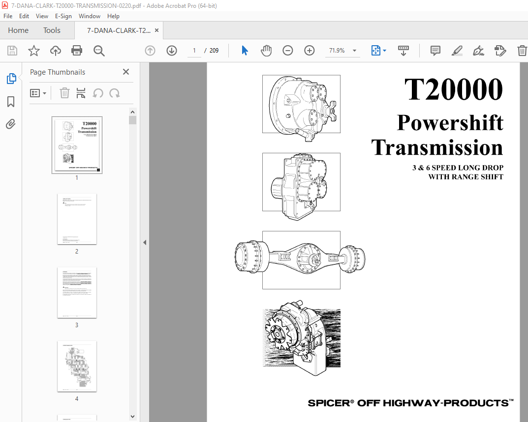
TABLE OF CONTENTS:
DANA Spicer T20000 Powershift Transmission Repair & Maintenance Manual – PDF DOWNLOAD
1 SAFETY PRECAUTIONS
2 CLEANING, INSPECTION AND LEGEND SYMBOLS
2 1 CLEANING 2-1
2 1 1 Bearings 2-1
2 1 2 Housings 2-1
2 2 INSPECTION 2-1
2 2 1 Bearings 2-1
2 2 2 Oil Seals, Gaskets, Etc 2-2
2 2 3 Gears and Shafts 2-2
2 2 4 Housing, Covers, etc 2-2
2 3 LEGEND SYMBOLS 2-2
3 TECHNICAL SPECIFICATIONS
3 1 IDENTIFICATION OF ТНЕ UNIT 3-1
3 2 WEIGHT, DIMENSIONS, OIL CAPACITY 3-1
3 3 ТIGHTENING TORQUES 3-2
3 3 1 Torque specifications for lubricated or plated screw threads 3-2
3 3 2 Elastic stop nut torque 3-3
3 3 3 “О” ring port plug torque chart 3-3
3 3 4 Pipe plug torque chart 3-3
3 3 5 Permanent metric plug torque chart 3-3
3 3 5 Coil and cartridge torque 3-4
3 4 PRESSURE AND TEMPERATURE SPECIFICATIONS 3-5
3 5 ELECTRICAL SPECIFICATIONS 3-6
3 6 HYDRAULIC COOLER AND FILTER LINE SPECIFICATIONS 3-6
4 MAINTENANCE
4 1 OIL SPECIFICATION 4-1
4 1 1 Recommended lubricants 4-1
4 2 MAINTENANCE INTERVALS 4-3
4 2 1 Daily 4-3
4 2 2 Normal drain period 4-3
4 3 SERVICING MACHINE AFTER COMPONENTS OVERHAUL 4-4
Т20000 3 & 6 LD RS 08/99 1-i
5 INSTALLATION DETAILS
5 1 CONVERTER DRIVE COUPLING 5-1
5 2 TRANSMISSION ТО ENGINE INSTALLATION PROCEDURE 5-2
5 3 EXTERNAL PLUMBING 5-3
5 3 1 Optional: remote filter 5-3
5 3 2 Cooler & filter lines specifications 5-3
5 4 SPEED SENSOR INSTALLATION 5-4
6 OPERATION OF ТНЕ TRANSMISSION
6 1 ТНЕ TRANSMISSION ASSEMBLY 6-1
6 1 1 The converter, pump drive section and pressure regulating valve 6-2
6 1 2 The input shaft and directional clutches 6-3
6 1 3 The range clutches 6-4
6 1 4 The output section 6-4
6 1 5 The transmission controls (refer to hydraulic diagram) 6-5
6 2 ELECTRIC SOLENOID CONTROLS 6-6
6 3 POWERFLOWS, ACТIVATED SOLENOIDS AND HYDRAULIC CIRCUIT
6 3 1 Neutral, 3rd clutch engaged and high range selected 6-7
6 3 2 Forward 1 st speed and high range selected 6-9
6 3 3 Forward 2nd speed and high range selected 6-11
6 3 4 Forward 3rd speed and high range selected 6-13
6 3 5 Reverse 1 st speed and high range selected 6-15
6 3 6 Forward 1st speed and low range selected 6-17
6 4 GEAR AND CLUTCH LAY-OUT 6-19
6 4 1 3-Speed with standard ratio 6-19
6 4 2 3-Speed with deep ratio 6-20
6 4 2 6-Speed with range shift 6-21
7 TROUBLESHOOTING GUIDE FOR ТНЕ Т20000 TRANSMISSION
7 1 Т20000 TRANSMISSION 7-1
7 2 TROUBLESHOOТING PROCEDURES 7-1
7 2 1 StallTest 7-1
7 2 2 Transmission pressure checks 7-2
7 2 3 Mechanical and electrical checks 7-2
7 2 4 Hydraulic checks 7-2
7 3 TROUBLESHOOТING GUIDE 7-3
7 3 1 Low clutch pressure 7-3
7 3 2 Low charging pump output 7-3
7 3 3 Overheating 7-3
7 3 4 Noisy converter 7-3
7 3 5 Lack of power 7-3
7 4 СНЕСК POINTS 7-4
7 5 SPEED SENSOR – STATIC STANDALONE TEST 7-7
Т20000 3 & 6 LD RS 08/99 1-ii
8 SECTIONAL VIEWS AND PARTS IDENTIFICATION
GROUP – CONVERTER HOUSING 8-2
GROUP – TRANSMISSION CASE AND REAR COVER 8-4
GROUP – TURBINE SHAFТ 8-6
GROUP – DRIVE PLATE 8-8
GROUP – TORQUE CONVERTER 8-10
GROUP -AUXILIARY PUMP DRIVE 8-12
GROUP – PUMP DRIVE 8-14
GROUP – FORWARD SHAFT 8-16
GROUP – REVERSE AND 2ND SHAFТ 8-18
GROUP – REVERSE IDLER 8-20
GROUP – LOW SPEED SHAFT 8-22
GROUP – 3RD SHAFТ 8-24
GROUP – IDLER SHAFТ (USED IN 6 SPEED AND 3 SPEED WITH DEEP RATIO) 8-26
GROUP – IDLER SHAFT (USED IN 3 SPEED STANDARD RATIO) 8-28
GROUP – OUTPUT SHAFТ (6 SPEED) 8-30
GROUP – OUTPUT SHAFТ (3 SPEED STANDARD RATIO) 8-32
GROUP – OUTPUT SHAFT ( 3 SPEED DEEP RATIO) 8-34
GROUP – HI & LOW RANGE SHIFТ CONTROL 8-36
GROUP – CHARGING PUMP & FILTER 8-38
GROUP – ELECTRIC CONTROL VALVE MOUNTING 8-40
GROUP – ELECTRIC CONTROL VALVE ASSEMBLY 8-42
9 ASSEMBLY INSTRUCTIONS
10 DISASSEMBLY AND REASSEMBLYT20000 LDTRANSMISSION
11 OPTIONS
11 1 HYDRAULIC ACTUATED AXLE DISCONNECT 11-1
11 1 1 Sectional views and parts identification 11-1
11 1 2 AssemЫy instructions 11-4
11 1 3 DisassemЫy of output shaft with axle disconnect 11-5
11 1 4 ReassemЫy of output shaft with axle disconnect 11-8
11 1 5 DisassemЫy of axle disconnect 11-11
11 1 6 ReassemЫy of axle disconnect 11-14
11 2 PARКING BRAKES 11-18
11 2 1 Mechanical Brake 11-18
11 2 1 1 Sectional views and parts identification 11-18
11 2 1 2 Adjustment and rebuild criteria 11-23
11 2 1 3 Replacing friction pads 11-23
11 2 1 4 DisassemЫy 11-24
11 2 1 5 Cleaning and inspection 11-24
11 2 1 6 AssemЫy 11-25
11 2 1 7 Replacing mount bushings 11-25
11 2 1 8 Servicing rotor assemЫy 11-25
Т20000 3 & 6 LD RS 08/99 1-iii
11 OPTIONS (Continued)
11 2 2 Spring applied hydraulic released brake (high pressure) 11-26
11 2 2 1 Sectional views and parts identification 11-26
11 2 2 2 Operation 11-31
11 2 2 3 Adjustment and rebuild criteria 11-31
11 2 2 4 Replacing friction pads 11-31
11 2 2 5 DisassemЫy 11-31
11 2 2 6 Cleaning and inspection 11-32
11 2 2 7 AssemЫy 11-32
11 2 2 8 lnstallation 11-33
11 2 2 9 Torque specs 11-33
11 2 3 Spring applied hydraulic released brake (low pressure) 11-34
11 2 3 1 Sectional views and parts identification 11-34
11 2 3 2 Operation 11-39
11 2 3 3 Adjustment and rebuild criteria 11-39
11 2 3 4 Replacing friction pads 11-39
11 2 3 5 DisassemЫy 11-39
11 2 3 6 Cleaning and inspection 11-40
11 2 3 7 AssemЫy 11-40
11 2 3 8 lnstallation 11-41
11 2 3 9 Torquespecs 11-41
12 SERVICE TOOLS
12 1 REVERSE IDLER SHAFT NUT SOCKET (TG 1304-54)
Т20000

