$33
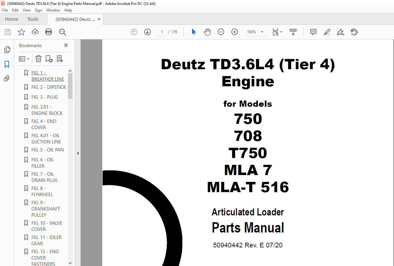
Deutz TD3.6L4 (Tier 4) Engine for Models 750 708 T750 MLA 7 MLA-T 516 Loader Parts Manual PDF
Deutz TD3.6L4 (Tier 4) Engine for Models 750 708 T750 MLA 7 MLA-T 516 Articulated Loader Parts Manual 50940442 – PDF DOWNLOAD
FILE DETAILS:
Deutz TD3.6L4 (Tier 4) Engine for Models 750 708 T750 MLA 7 MLA-T 516 Articulated Loader Parts Manual 50940442 – PDF DOWNLOAD
Language : English
Pages : 176
Downloadable : Yes
File Type : PDF
Size: 47.1 MB
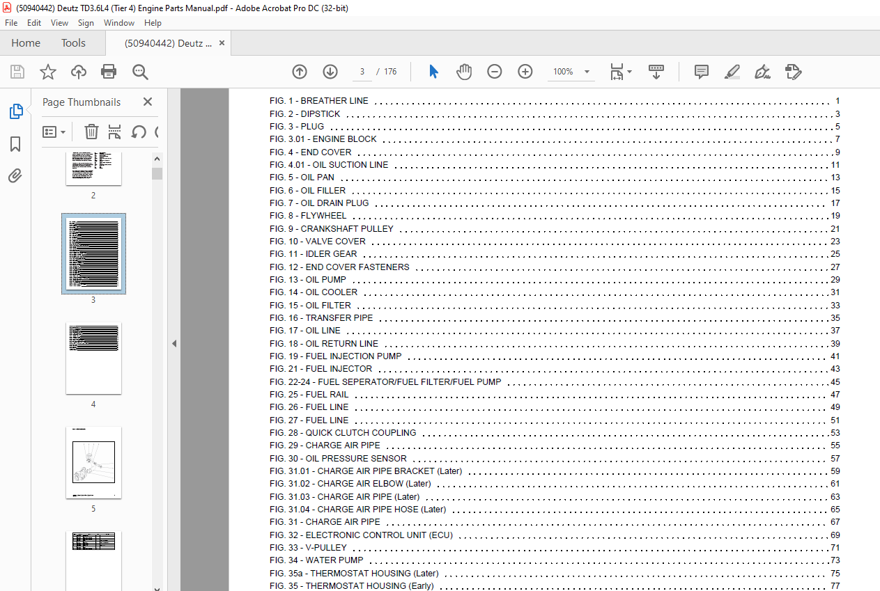
TABLE OF CONTENTS:
Deutz TD3.6L4 (Tier 4) Engine for Models 750 708 T750 MLA 7 MLA-T 516 Articulated Loader Parts Manual 50940442 – PDF DOWNLOAD
FIG. 1 – BREATHER LINE 1
FIG. 2 – DIPSTICK 3
FIG. 3 – PLUG 5
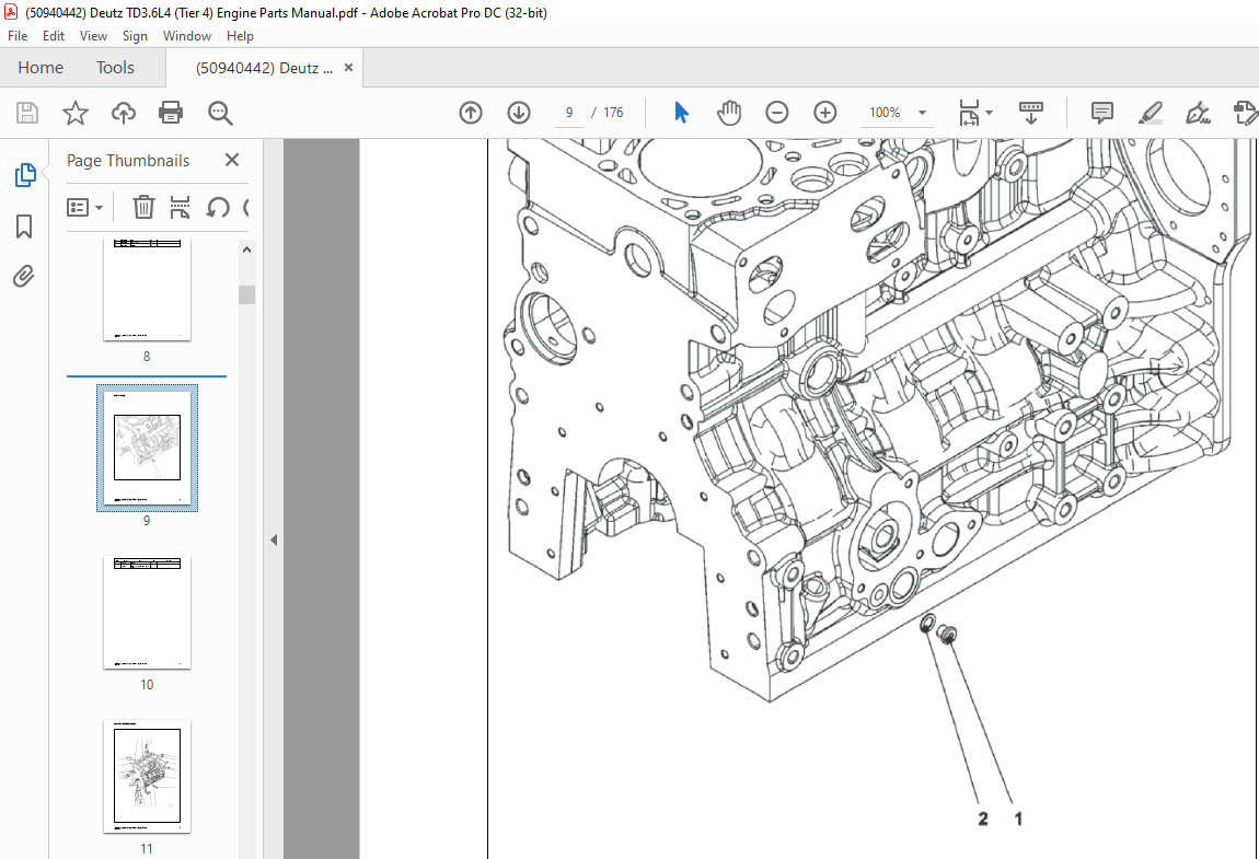
FIG. 3.01 – ENGINE BLOCK 7
FIG. 4 – END COVER 9
FIG. 4.01 – OIL SUCTION LINE 11
FIG. 5 – OIL PAN 13
FIG. 6 – OIL FILLER 15
FIG. 7 – OIL DRAIN PLUG 17
FIG. 8 – FLYWHEEL 19
FIG. 9 – CRANKSHAFT PULLEY 21
FIG. 10 – VALVE COVER 23
FIG. 11 – IDLER GEAR 25
FIG. 12 – END COVER FASTENERS 27
FIG. 13 – OIL PUMP 29
FIG. 14 – OIL COOLER 31
FIG. 15 – OIL FILTER 33
FIG. 16 – TRANSFER PIPE 35
FIG. 17 – OIL LINE 37
FIG. 18 – OIL RETURN LINE 39
FIG. 19 – FUEL INJECTION PUMP 41
FIG. 21 – FUEL INJECTOR 43
FIG. 22-24 – FUEL SEPERATOR/FUEL FILTER/FUEL PUMP 45
FIG. 25 – FUEL RAIL 47
FIG. 26 – FUEL LINE 49
FIG. 27 – FUEL LINE 51
FIG. 28 – QUICK CLUTCH COUPLING 53
FIG. 29 – CHARGE AIR PIPE 55
FIG. 30 – OIL PRESSURE SENSOR 57
FIG. 31.01 – CHARGE AIR PIPE BRACKET (Later) 59
FIG. 31.02 – CHARGE AIR ELBOW (Later) 61
FIG. 31.03 – CHARGE AIR PIPE (Later) 63
FIG. 31.04 – CHARGE AIR PIPE HOSE (Later) 65
FIG. 31 – CHARGE AIR PIPE 67
FIG. 32 – ELECTRONIC CONTROL UNIT (ECU) 69
FIG. 33 – V-PULLEY 71
FIG. 34 – WATER PUMP 73
FIG. 35a – THERMOSTAT HOUSING (Later) 75
FIG. 35 – THERMOSTAT HOUSING (Early) 77
FIG. 36 – COOLANT LINE 79
FIG. 37 – COOLANT PIPE (Early) 81
FIG. 38a – EGR COOLER (Later) 83
FIG. 38 – EGR COOLER (Early) 85
FIG. 39 – EGR CONNECTOR 87
FIG. 40 – INTAKE EXPANSION JOINT 89
FIG. 41 – EGR BRACKET 91
FIG. 42 – EGR COOLANT PIPE 93
FIG. 43 – EGR COOLANT LINE 95
FIG. 44 – EGR BRACKET 97
FIG. 45 – COOLANT LINE PLUG 99
FIG. 39a – EXHAUST PIPE (Later) 101
FIG. 46.01 – EXHAUST MANIFOLD (SN 12460170 and Up) 103
FIG. 46 – EXHAUST MANIFOLD (SN 12460169 and Before) 105
FIG. 47 – TURBOCHARGER 107
FIG. 48 – EXHAUST CONNECTION 109
FIG. 49 – V-BELT 111
FIG. 50.01 – ALTERNATOR (Later) 113
FIG. 50 – ALTERNATOR (Early) 115
FIG. 51 – ALTERNATOR ADJUSTMENT BRACKET 117
FIG. 52 – ALTERNATOR BRACKET 119
FIG. 53 – STARTER 121
FIG. 54 – PLUG-IN CONNECTOR 123
FIG. 55 – RELAY 125
FIG. 56 – STARTER RELAY CABLE 127
FIG. 57 – PROTECTION CAP 129
FIG. 58 – PLUG-IN CONNECTOR 131
FIG. 59 – WIRE HARNESS FASTENERS 133
FIG. 60.01 – WIRE HARNESS (Later) 135
FIG. 60 – WIRE HARNESS (Early) 137
FIG. 61 – TACHO-ALTERNATOR 139
FIG. 62 – TACHOMETER SENSOR 141
FIG. 62a – PRESSURE SENSOR 143
FIG. 63 – FLYWHEEL HOUSING 145
FIG. 63a – FLYWHEEL HOUSING BRACKET 147
FIG. 64 – GLOW PLUGS 149
FIG. 65.01 – DOC PARTICULATE FILTER (Later) 151
FIG. 65.02 – DOC TEMPERATURE TRANSMITTER (Later) 153
FIG. 65 – DOC BRACKET 155
FIG. 65a – DOC RISER 157
FIG. 67 – DOC CLAMP 159
FIG. 75 – GASKETS 161
Appendix A:Pages Index 163
Appendix B:Parts Index 164
DESCRIPTION:
Deutz TD3.6L4 (Tier 4) Engine for Models 750 708 T750 MLA 7 MLA-T 516 Articulated Loader Parts Manual 50940442 – PDF DOWNLOAD
Introduction:
- For your safety and continued proper operation, use only genuine XPRT® Genuine Parts. When ordering service parts, specify the correct part number, full description, quantity required, the unit model number, and serial number. The model and serial number decal for this unit are located on the left chassis upright.
- Manitou Americas reserves the right to make changes or improvements in the design or construction of any part of the unit without incurring the obligation to install such changes on any previously delivered units. Purchase equivalent, quality XPRT tires for your loader. Contact your dealer for replacement tire information. Replacement batteries are not provided by Manitou Americas. Battery specifications are listed in the Electrical section where the battery is shown. ALL REPLACEMENT BATTERIES MUST BE PURCHASED LOCALLY.
How to Use This Manual:
- “Right” and “Left” are determined from a position sitting on the seat and facing forward. Unless otherwise indicated, all parts page graphics are shown as viewed from the front left. If the view is from a different perspective, a directional arrow on the lower-left corner will identify the front of the machine. Items shown in the parts list that do not have part numbers are shown for reference purposes only and are NOT available for purchase. Dimensions are in inches unless otherwise specified.
- Refer to the abbreviations table to the right for various fastener descriptions. Standard hardware torque values are provided at the end of this manual. For parts requiring non-standard torque values, the correct torque value will appear on the parts page graphic or parts list next to the corresponding item number.
IMAGES PREVIEW OF THE MANUAL:
More products