$30
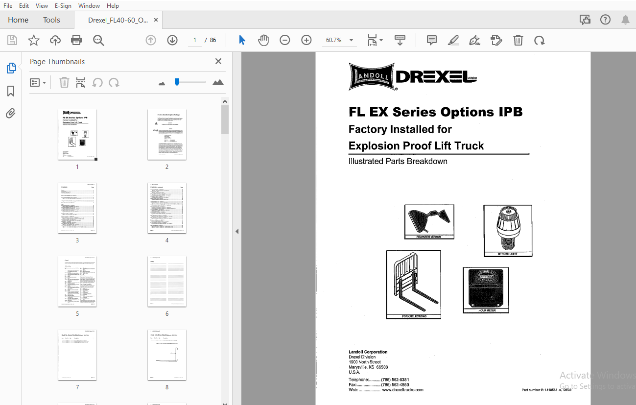
Drexel FL EX Series Options IPB Explosion Proof Lift Truck Parts Manual 1418583 – PDF DOWNLOAD
Drexel FL EX Series Options IPB Explosion Proof Lift Truck Parts Manual 1418583 – PDF DOWNLOAD
FILE DETAILS:
Drexel FL EX Series Options IPB Explosion Proof Lift Truck Parts Manual 1418583 – PDF DOWNLOAD
Language : English
Pages : 86
Downloadable : Yes
File Type : PDF
IMAGES PREVIEW OF THE MANUAL:

TABLE OF CONTENTS:
Drexel FL EX Series Options IPB Explosion Proof Lift Truck Parts Manual 1418583 – PDF DOWNLOAD
General 5
Abbreviations 5
Phantoms/ Reference Parts 5
Task Groups/Assemblies 5
Back Up Alarm Modification, p/n: 1404516-A 7
Fork, with Brass Sheathing, p/n: 50105-03-G 8
Figure 1: Fork, with Brass Sheathing, p/n: 50105-03-G 8
Handbrake Interlock Group, p/n: 1414771-A 9
Figure 2: Handbrake Interlock Group, p/n: 1414771-A 10
Paint, Yellow Enamel, p/n: 37260-04-A 12
Lights
Strobe Light Assembly, p/n: 1410703-C 13
Figure 3: Strobe Light Assembly, p/n: 1410703-C 14
Strobe Light Installation, p/n: 1414212-A 15
Figure 4: Strobe Light Installation, p/n: 1414212-A 16
Strobe Light, Modified, p/n: 1411822-A 17
Figure 5: Strobe Light, Modified, p/n: 1411822-A 18
Strobe Light, Amber, p/n: 1410315-A 19
Figure 6: Strobe Light, Amber, p/n: 1410315-A 20
Tire Group, Smooth, p/n: 18262-A 21
Figure 7: Tire Group, Smooth, p/n: 18262-A 21
Hydraulic Assembly, p/n: 18056-07-F 23
Hydraulic Assembly, p/n: 18056-07-F (continued) 24
Figure 8-1: Hydraulic Assembly, p/n: 18056-07-F (sheet 1 of 2) 25
Figure 8-2: Hydraulic Assembly, p/n: 18056-07-F (sheet 2 of 2) 27
Valve Control Assembly, p/n: 18211-02-G 28
Figure 8-3: Valve Control Assembly, p/n: 18211-02-G 29
Control Valve, p/n: 27757-A 30
Figure 8-4: Control Valve, p/n: 27757-A 31
Valve Assembly, Check, p/n: 50426-J 33
Figure 8-5: Valve Assembly, Check p/n: 50426-J , 33
Tank Hydraulic Assembly, p/n: 18043-01-A 34
Figure 8-6: Tank Hydraulic Assembly, p/n: 18043-01-A (sheet 1 of 2) 35
Figure 8-7: Tank Hydraulic Assembly, p/n: 18043-01-A (sheet 2 of 2) 37
Tilt Cylinder Assembly, p/n: 9822-05-A 39
Figure 8-8: Tilt Cylinder Assembly, p/n: 9822-05-A 39
Tilt Cylinder, p/n: 6982-K 40
Figure 8-9: Tilt Cylinder; p/n: 6982-K 41
Pump and Motor Assembly, p/n: 9510-02-E 42
Figure 8-1 O: Pump and Motor Assembly, p/n: 9510-02-E 43
Pump and Motor Assembly, p/n: 18055-C 44
Figure 8-11: Pump and Motor Assembly, p/n: 18055-C 45
Power Steering Pump, p/n: 50654-A 46
Figure 8-12: Power Steering Pump, p/n: 50654-A 47
Steering Control Unit, p/n: 25715-B 48
Figure 8-13: Steering Control Unit, p/n: 25715-B 49
Hydraulic Assembly, p/n: 18056-08-E 52
Hydraulic Assembly, p/n: 18056-08-E (continued) 53
Figure 8-14: Hydraulic Assembly 4 Spool Valve, p/n: 18056-08-E (sheet 1 of 2) 54
Figure 8-15: Hydraulic Assembly 4 Spool Valve, p/n: 18056-08-E (sheet 2 of 2) 55
Valve Control Assembly, p/n: 18211-03-E 56
Figure 8-16: Valve Control Assembly 4 p/n: 18211-03-E 57
Tank Hydraulic Assembly, pin: 18043-01-A 58
Figure 8-17: Tank Hydraulic Assembly, p/n: 18043-01-A 59
Figure 8-18: Tank Hydraulic Assembly, p/n: 18043-01-A (sheet 2 of 2) 61
Tilt Cylinder Assembly, p/n: 9822-05-A 62
Figure 8-19: Tilt Cylinder Assembly, p/n: 9822-05-A 63
Tilt Cylinder, p/n: 6982-K 64
Figure 8-20: Tilt Cylinder, p/n: 6982-K 65
Pump and Motor Assembly, p/n: 9510-02-E 66
Figure 8-21: Pump and Motor Assembly, p/n: 9510-02-E 67
Cable Operated Horn, 3-Spool, p/n: 1419728-A 70
Figure 8-22: Cable Operated Horn, 3-Spool, p/n: 1419728-A 71
Cable Operated Horn, 4-Spool, p/n: 1420988-A 74
Figure 8-23: Cable Operated Horn, 4-Spool, p/n: 1420988-A 75
Tilt Cylinder Modification, p/n: 9822-08-A 77
Tilt Cylinder Breakdown, p/n: 6982-K 78
Figure 8-24: Tilt Cylinder Breakdown, p/n: 6982-K 79
Pin Pivot Weldment Assembly, p/n: 1420652-A 81
Figure 8-25: Pin Pivot Weldment Assembly, p/n: 1420652-A 81
Decal Kit, Russian, p/n: 1420565-A 83
Figure 8-26: Decal Kit, Russian, p/n: 1420565-A (sheet 1 of 2) 84
Figure 8-27: Decal Kit, Russian, p/n: 1420565-A (sheet 2 of 2) 85


