$29
Drexel R40 LPG Engine & Transmission SwingMast Lift Truck Parts Manual_1416917 – PDF DOWNLOAD
Drexel R40 LPG Engine & Transmission SwingMast Lift Truck Parts Manual_1416917 – PDF DOWNLOAD
FILE DETAILS:
Drexel R40 LPG Engine & Transmission SwingMast Lift Truck Parts Manual_1416917 – PDF DOWNLOAD
Language : English
Pages : 72
Downloadable : Yes
File Type : PDF
IMAGES PREVIEW OF THE MANUAL:
![]()
TABLE OF CONTENTS:
Drexel R40 LPG Engine & Transmission SwingMast Lift Truck Parts Manual_1416917 – PDF DOWNLOAD
R-40-SL “LPG” Engine/Transmission IPB
General 5
Abbreviations 5
Phantoms/ Reference Parts 5
Task Groups/Assemblies 5
Engine
Cylinder Block Assembly 8
Figure 1: Cylinder Block Assembly 9
Crankshaft, Pistons and Connecting Rods 10
Figure 2: Crankshaft, Pistons and Connecting Rods 11
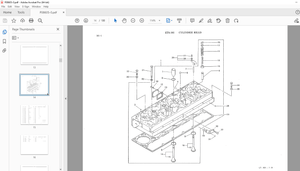
Cylinder Head 12
Figure 3: Cylinder Head 13
Rocker Shaft 14
Figure 4: Rocker Shaft 15
Time Gear and Camshaft 16
Timing Gear and Camshaft (continued) 17
Figure 5: Timing Gear and Camshaft 19
Oil Pump and Deliver Housing 20
Figure 6: Oil Pump and Deliver Housing 21
Carburetor and Ignition 22
Figure 7: Carburetor and lgnition 23
Lubricating Oil Sump 24
Lubricating Oil Sump (continued) 25
Figure 8: Lubricating Oil Sump 27
Oil Filler Breather 28
Figure 9: Oil Filler Breather 29
Oil Filter and Cooler 30
Figure 10: Oil Filter and Cooler 31
Front End Drive lnput 32
Figure 11: Front End Drive Input 33
Water Pump 34
Water Pump (continued) 35
Figure 12: Water Pump 37
Thermostat and Heat Exchanger 38
Figure 13: Thermostat and Heat Exchanger 39
Fan and Extension 41
Figure 14: Fan and Extension 41
Alternator and Generator 42
Figure 15: Alternator and Generator 43
R40SL LPG, G4 236 Engine IPB, p/n: 51956-01 -b, 08/03 3
D Table of Contents
IPB Contents – continued Page
Induction Manifold 44
Figure 16: Induction Manifold 45
Exhaust Manifold 46
Figure 17: Induction Manifold 46
Exhaust Outlet Flange 47
Figure 18: Exhaust Outlet Flange 47
Low Pressure Fuel System 48
Figure 19: Low Pressure Fuel System 48
Engine Lifting 49
Figure 20: Low Pressure Fuel System 49
Front and Rear Mountings 50
Figure 21: Front and Rear Mountings 50
Tachometer and Hour Recorder 51
Figure 22: Tachometer and Hour Recorder 51
Top Service Kit (Joints and Gaskets) 52
Figure 23: Top Service Kit (Joints and Gaskets) 52
Bottom Service Kit (Joints and Gaskets) 53
Figure 24: Bottom Service Kit (Joints and Gaskets) 53
Transmission
PR1 Transmission Assembly, p/n: 51660-8 : 55
PR1 Transmission Assembly, p/n: 51660-8 (continued) 56
PR1 Transmission Assembly, p/n: 51660-8 (continued) : 57
Figure 8-1: PR1 Transmission Assembly, p/n: 51660-8 (sheet 1 of 2) 58
Figure 8-2: PR1 Transmission Assembly, p/n: 51660-B (sheet 2 of 2) 59
Forward Shaft Assembly, p/n: 51663-A 60
Figure 8-3: Forward Shaft Assembly, p/n: 51663-A 61
Cylinder and Plug Shaft, p/n: 51664 63
Figure 8-4: Cylinder and Plug Shaft, p/n: 51664 63
Input Shaft Assembly, p/n: 51665-A : 64
Figure 8-5: Input Shaft Assembly, p/n: 51665-A 65
Clutch Cylinder and Plug, p/n: 51666 67
Figure 8-6: Clutch Cylinder and Plug, p/n: 51666 67
Front Pump Assembly, p/n: 57242-8 68
Figure 8-7: Front Pump Assembly, p/n: 57242-8 69
Valve Body Assembly, p/n: 70395-A 70
Figure 8-8: Valve Body Assembly, p/n: 70395-A 71
Cover and Bushing Assembly, p/n: 51675-A 72
Figure 8-9: Cover and Bushing Assembly, p/n: 51675-A 72
More products