$36
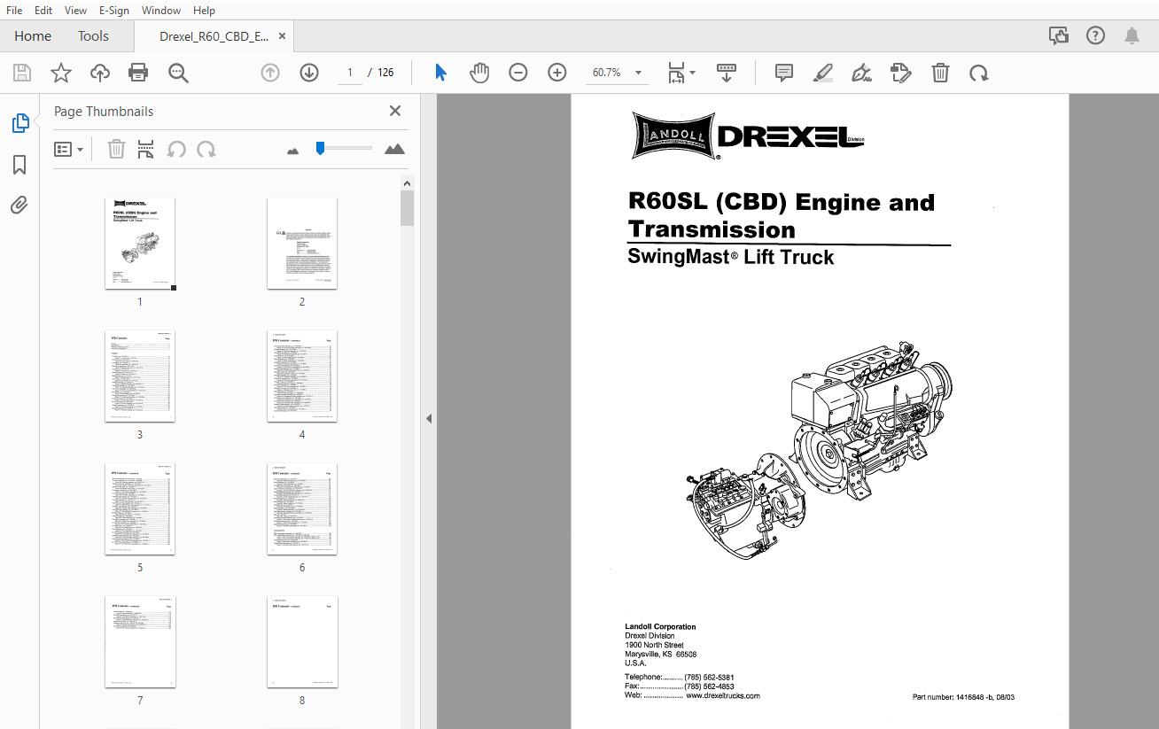
DREXEL R60SL (CBD) Engine & Transmission SwingMast Lift Truck Parts Manual_1416848 – PDF DOWNLOAD
DREXEL R60SL (CBD) Engine & Transmission SwingMast Lift Truck Parts Manual_1416848 – PDF DOWNLOAD
FILE DETAILS:
DREXEL R60SL (CBD) Engine & Transmission SwingMast Lift Truck Parts Manual_1416848 – PDF DOWNLOAD
Language : English
Pages : 126
Downloadable : Yes
File Type : PDF
IMAGES PREVIEW OF THE MANUAL:

TABLE OF CONTENTS:
DREXEL R60SL (CBD) Engine & Transmission SwingMast Lift Truck Parts Manual_1416848 – PDF DOWNLOAD
General ?
Abbreviations 7
Phantoms / Reference Parts 7
Task Groups/Assemblies 7
Engine
Lock Cap, p/n: 1421133-A 10
Figure 1: Lock Cap, p/n: 1421133-A 1 O
Guide Tube, p/n: 1421135-A 11
Figure 2: Guide Tube, p/n: 1421135-A 11
Fastenings, p/n: 1421143-A 12
Figure 3: Fastenings, p/n: 1421143-A 13
Blanking Assembly, p/n: 1421157-A 14
Figure 4: Blanking Assembly, p/n: 1421157-A 14
Fastening, p/n: 1421164-A 15
Figure 5: Fastening, p/n: 1421164-A 15
Nozzle Assembly, p/n: 1421171-A 16
Figure 6: Nozzle, p/n: 1421171-A 16
Blanking Parts, p/n: 142117 4-A 17
Figure 7: Blanking Parts, p/n: 1421174-A 17
Cover Plate, p/n: 1421179-A 18
Figure 8: Cove Plate, p/n: 1421179-A 18
Dipstick Assembly, p/n: 1421181-A 19
Figure 9: Dipstick Assembly, p/n: 1421181-A 19
Crankcase Breather, p/n: 1421193-A 20
Figure 10: Crankcase Breather, p/n: 1421193-A 20
Front Cover Assembly, p/n: 1421184-A 21
Figure 11: Front Cover Assembly, p/n: 1421184-A 21
Idler Bearing, p/n: 1421203-A 23
Figure 12: Idler Bearing, p/n: 1421203-A 23
Crankcase Assembly, p/n: 1421209-A 24
Figure 13: Crankcase Assembly, p/n: 1421209-A 25
Tensioning Pulley, p/n: 1421231-A 26
Figure 14: Tensioning Pulley, p/n: 1421231-A 27
Oil Pan Assembly, p/n: 1421241-A 28
Figure 15: Oil Pan Assembly, p/n: 1421241-A 29
Cylinder Assembly, p/n: 1421243-A 30
Figure 16: Cylinder Assembly, p/n: 1421243-A 30
Vibration Damper, p/n: 1421245-A 31
Figure 17: Vibration Damper, p/n: 1421245-A 31
V-Grooved Pulley Assembly, p/n: 1421246-A 32
Figure 18: V-Grooved Pulley Assembly, p/n: 1421246-A 32
Flywheel Assembly, p/n: 1421248-A ‘ 33
Figure 19: Flywheel Assembly, p/n: 1421248-A 33
Crankshaft Assembly, p/n: 1421250-A 34
Figure 20: Crankshaft Assembly, p/n: 1421250-A 35
Connecting Rod, p/n: 1421255-A 36
Figure 21: Connecting Rod, p/n: 1421255-A 36
Piston Assembly, p/n: 1421258-A 37
Figure 22: Piston Assembly, p/n: 1421258-A 37
Fastening Assembly, p/n: 1421262-A 38
Figure 23: Fastening Assembly, p/n: 1421262-A 38
Valve Cover, Mechanical, p/n: 1421263-A 39
Figure 24: Valve Cover, Mechanical, p/n: 1421263-A 39
Cylinder Head Assembly, p/n: 1421268-A 40
Figure 25: Cylinder Head Assembly, p/n: 1421268-A 41
Camshaft, Output, p/n: 1421282-A 42
Figure 26: Camshaft, Output, pin: 1421282-A 42
Camshaft Assembly, p/n: 1421283-A 43
Figure 27: Camshaft Assembly, p/n: 1421283-A 43
Valve Drive Assembly, p/n: 1421287-A 44
Figure 28: Valve Drive Assembly, p/n: 1421287-A 45
Protector Tube; p/ri: 1421285-A 46
Figure 29: Protector Tube, p/n: 1421285-A 46
Oil Pump Assembly, pin: 1421288-A :: 47
Figure 30: Oil Pump Assembly, p/n: 1421288-A 47
Hydraulic Oil Cooler, p/n: 1421298-A 48
Figure 31: Hydraulic Oil Cooler, p/n: 1421298-A 49
Filter Cartridge, p/n: 1421300-A 51
Figure 32: Filter Cartridge, p/n: 1421300-A 51
Changeover Switch Assembly, p/n: 1421301-A 52
Figure 33: Changeover Switch Assembly, p/n: 1421301-A 53
Oil Pressure Line Assembly, p/n: 1421304-A 54
Figure 34: Oil Pressure Line Assembly, p/n: 1421304-A 54
Oil Suction Pipe Assembly, p/n: 1421305-A 55
Figure 35: Oil Suction Pipe Assembly, p/n: 1421305-A 55
Overflow Valve Assembly, p/n: 1421307-A 56
Figure 36: Overflow Valve Assembly, p/n: 1421307-A 56
Oil Line Assembly, p/n: 1421308-A 57
Figure 37: Oil Line Assembly, p/n: 1421308-A 57
Governor Assembly, p/n: 1421310-A 58
Governor Assembly, p/n: 1421310-A – continued 59
Governor Assembly, p/n: 1421310-A- continued 60
Figure 38: Governor Assembly, p/n: 1421310-A 61
Injection Fuel Pump Assembly, p/n: 1421349-A 62
Figure 39: Injection Fuel Pump Assembly, p/n: 1421349-A 63
Injection Pump Drive, p/n: 1421350-A 64
Figure 40: Injection Pump Drive, p/n: 1421350-A 64
Fuel Injector Assembly, p/n: 1421356-A 65
Figure 41: Fuel Injector Assembly, p/n: 1421356-A 65
Fuel Filter Assembly, p/n: 1421366-A 66
Figure 42: Fuel Filter Assembly, p/n: 1421366-A 67
Leak-Off Line Assembly, p/n: 1421370-A 68
Figure 43: Leak-Off Line Assembly, p/n: 1421370-A 68
Fuel Line Assembly, p/n: 1421371-A 69
Figure 44: Fuel Line Assembly, p/n: 1421371-A 69
High Pressure Pipe Assembly, p/n: 1421373-A 70
Figure 45: High Pressure Pipe Assembly, p/n: 1421373-A 71
Overflow Line Assembly, p/n: 1421378-A , 72
Figure 46: Overflow Line Assembly, p/n: 1421378-A 72
Intake Manifold Assembly, p/n: 1421380-A 73
Figure 47: Intake Manifold Assembly, p/n: 1421380-A 73
Blanking Parts, p/n: 1421384-A 74
Figure 48: Blanking Parts, p/n: 1421384-A 74
V-BeltAssembly, p/n: 1421389-A 75
Figure 49: V-Belt Assembly, p/n: 1421389-A 75
Cooling Fan Assembly, p/n: 1421386-A 76
Figure 50: Cooling Fan Assembly, p/n: 1421386-A 77
Air Duct Wall Assembly, p/n: 1421390-A 78
Figure 51: Air Duct Wall Assembly, p/n: 1421390-A 79
Air Outlet Frame, p/n: 1421391-A 80
Figure 52: Air Outlet Frame, p/n: 1421391-A 80
Cover Assembly, p/n: 1421393-A 81
Figure 53: Cover Assembly, p/n: 1421393-A 81
Air Cowling Base Assembly, p/n: 1421396-A 82
Figure 54: Air Cowling Base Assembly, p/n: 1421396-A 82
Cooling Air Baffle Assembly, p/n: 1421400-A 83
Figure 55: Cooling Air Baffle Assembly, p/n: 1421400-A 83
Piston Guide Ring Assembly, p/n: 1421401-A 84
Figure 56: Piston Guide Ring Assembly, p/n: 1421401-A 84
Air Outlet Frame Assembly, p/n: 1421402-A 85
Figure 57: Air Outlet Frame Assembly, p/n: 1421402-A 85
Guide Rail Assembly, p/n: 1421407-A 86
Figure 58: Guide Rail Assembly, p/n: 1421407-A 86
Cover Assembly, p/n: 1421408-A 87
Figure 59: Cover Assembly, p/n: 1421408-A 87
Air Guided Hood Assembly, p/n: 1421406-A 88
Figure 60: Air Guided Hood Assembly, p/n: 1421406-A 89
Cool Air Feed Duct Assembly, p/n: 1421414-A 90
Figure 61: Cool Air Feed Duct Assembly, p/n: 1421414-A 90
Exhaust Manifold Assembly, p/n: 1421416-A 91
Figure 62: Exhaust Manifold Assembly, p/n: 1421416-A 91
Air Duct Wall Assembly, p/n: 1421411-A 92
Figure 63: Air Duct Wall Assembly, p/n: 1421411-A 93
Flange Assembly, p/n: 1421419-A 94
Figure 64: Flange Assembly, p/n: 1421419-A 94
Seals, Gaskets, p/n: 1421420-A 95
Figure 65: Seals, Gaskets, p/n: 1421420-A 95
Protecting Cap, p/n: 1421422-A 96
Figure 66: Protecting Cap, p/n: 1421422-A 96
Starter Assembly, p/n: 1421423-A 97
Figure 67: Starter Assembly, p/n: 1421423-A : • 97
Stop Switch Mount Assembly; p/n: 1421428-A 98
Figure 68: Stop Switch Mount Assembly, p/n: 1421428-A 99
Plug, p/n: 1421474-A : : • : :: : : 100
Figure 69: Plug, p/n: 1421474-A • 100
Connection Housing Assembly, p/n: 1421475-A • , 101
Figure 70: Connection Housing Assembly, p/n: 1421475-A 101
Cover Plate Assembly, p/n: 1421476-A 102
Figure 71: Cover Plate Assembly, p/n: 1421476-A : 102
Gasket Kit Assembly, p/n: 1421426-A 103
Figure 72: Gasket Kit Assembly, p/n: 1421426-A 103
Transmission
PR2 Transmission Assembly, p/n: 1405132-C 105
PR2 Transmission Assembly, p/n: 1405132-C (continued) • 106
Figure 1: PR2 Transmission Assembly, p/n: 1405132-C (sheet 1 of 2) 107
Figure 2: PR2 Transmission Assembly, p/n: 1405132-C (sheet 2 of 2) 109
Valve Body Assembly, p/n: 1405126-8 110
Figure 3: Valve Body Assembly, p/n: 1405126-8 111
Forward Shaft Assembly, p/n: 1405121-B 112
Figure 4: Forward Shaft Assembly, p/n: 1405121-B 113
Forward Shaft, p/n: 1405120-A 115
Figure 5: Forward Shaft, p/n: 1405120-A 115
Input Shaft Assembly, p/n: 1405125-B 116
Figure 6: Input Shaft Assembly, p/n: 1405125-B 117
Input Shaft Sub-Assembly, p/n: 1405124-A 118
Figure 7: Input Shaft Sub-Assembly, p/n: 1405124-A 118
Auxiliary Pump Drive, p/n: 1405131-B 119
Auxiliary Pump Drive, p/n: 1405131-B (continued) 120
Figure 8: Auxiliary Pump Drive, p/n: 1405131-B 121
Front Pump Assembly, p/n: 57242-B 122
Figure 9: Front Pump Assembly, p/n: 57242-B 123


