$41
Drexel R60SL LPG Series Base IPB SwingMast Lift Truck Parts Manual 1411284 – PDF DOWNLOAD
Drexel R60SL LPG Series Base IPB SwingMast Lift Truck Parts Manual 1411284 – PDF DOWNLOAD
FILE DETAILS:
Drexel R60SL LPG Series Base IPB SwingMast Lift Truck Parts Manual 1411284 – PDF DOWNLOAD
Language : English
Pages : 510
Downloadable : Yes
File Type : PDF
IMAGES PREVIEW OF THE MANUAL:
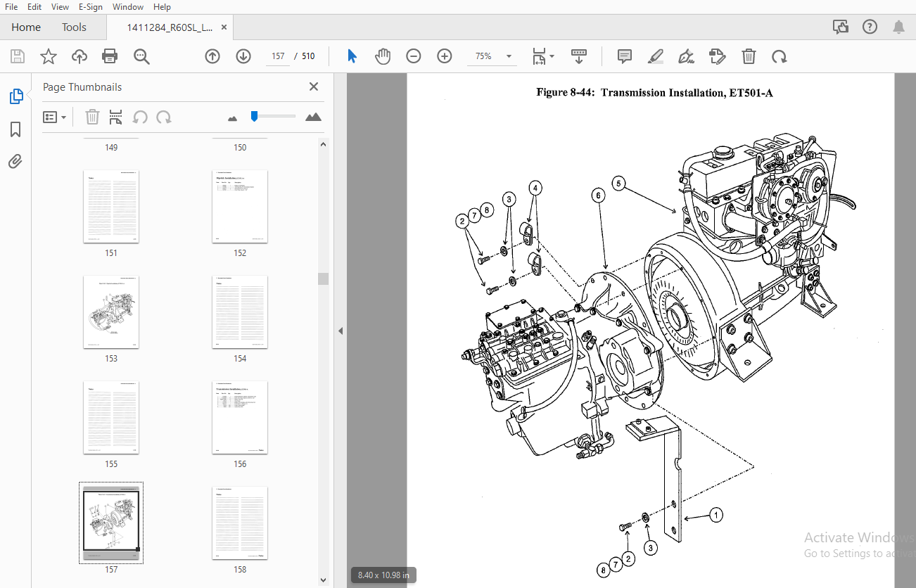
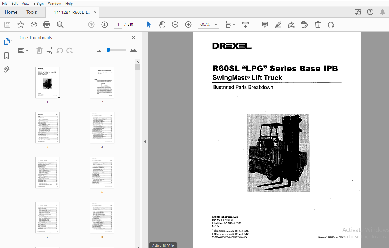
TABLE OF CONTENTS:
Drexel R60SL LPG Series Base IPB SwingMast Lift Truck Parts Manual 1411284 – PDF DOWNLOAD
General 8-11
Abbreviations 8-11
Phantoms/ Reference Parts 8-11
Task Groups/Assemblies 8-11
Drive Axle Installation, DA326-A 8-14
Figure 8-1 Drive Axle Installation, DA326-A 8-15
U-joint Installation, DA322 1-A 8-18
Figure 8-2 U-joint Installation, DA322 1-A 8-19
Drive Axle, Modified, DA322-A 8-22
Figure 8-3 Drive Axle, Modified, DA322-A 8-23
Disk Brake Service, p/n 1415954-A 8-24
Figure 8-4 Disk Brake Service, p/n 1415954-A 8-25
Differential Breakdown, p/n 1410322-A 8-26
Differential Breakdown, p/n 1410322-A (continued) 8-27
Figure 8-5 Differential Breakdown, p/n 1410322-A 8-29
Axle Breakdown, p/n 1415946-A 8-30
Axle Breakdown, p/n 1415946-A (Continued) 8-31
Figure 8-6 Axle Breakdown, p/n 1415946-A 8-33
Housing and Covers, Service, p/n 1415933-A 8-34
Figure 8-7 Housing and Covers, Service, p/n 1415933-A 8-35
Master Cylinder Tube Installation, DA469-A 8-38
Figure 8-8 Master Cylinder Tube Installation, DA469-A 8-39
D A Brake Tube Installation, DA324-A 8-42
Figure 8-9 D A Brake Tube Installation, DA324-A 8-43
Park Brake Cable Connection, DA481-A 8-46
Figure 8-10 Park Brake Cable Connection, DA481-A 8-47
Brake Linkage Installation, OH396-B 8-50
Figure 8-11 Brake Linkage Installation, OH396-B 8-51
Master Cylinder, Brake, p/n 1407337-A 8-52
Figure 8-12 Master Cylinder, Brake, p/n 1407337-A 8-52
Brake Line Installation, OH405-B 8-54
Figure 8-13 Brake Line Installation, OH405-B 8-55
Brake Pedal Sub-Assembly, OH467-C 8-58
Figure 8-14 Brake Pedal Sub-Assembly, OH467-C 8-59
Lower Cam Sub-Assembly, OH466-C 8-61
Figure 8-15 Lower Cam Sub-Assembly, OH466-C 8-61
Park Brake Installation, DA326 1-A 8-64
Figure 8-16 Park Brake Installation, DA326 1-A 8-65
Park Brake Installation, OH391-B 8-68
Figure 8-17 Park Brake Installation, OH391-B 8-69
Park Brake Switch Assembly, OH465-B 8-72
Figure 8-18 Park Brake Switch Assembly, OH465-B 8-73
Steer Axle Installation, SA478-A 8-76
Figure 8-19 Steer Axle Installation, SA478-A 8-77
Steer Axle Assembly, p/n 1407432-D 8-78
Figure 8-20 Steer Axle Assembly, pin 1407432-D (sheet 1 of 2) , 8-79
Figure 8-21 Steer Axle Assembly, pin 1407432-D (sheet 2 of 2) 8-81
Steering Cylinder, pin 2805184-A 8-82
Figure 8-22 Steering Cylinder, pin 2805184-A 8-83
Axle Oscillation Pad Installation, SA457-A 8-85
Figure 8-23 Axle Oscillation Pad Installation, SA457-A 8-85
Rear Tires and Nuts, SA361-A 8-87
Figure 8-24 Rear Tires and Nuts, SA361-A 8-87
Steering Tire and Wheel Assembly, p/n 1400854-8 8-88
Figure 8-25 Steering Tire and Wheel Assembly, p/n 1400854-8 8-88
Drive Tire Nut Re-torque, IA492-E , 8-90
Figure 8-26 Drive Tire Nut Re-torque, IA492-E 8-91
Accelerator Pedal Assembly, OH476-C 8-93
Figure 8-27 Accelerator Pedal Assembly, OH476-C 8-93
Accelerator Cable Installation, OH404-A 8-96
Figure 8-28 Accelerator Cable Installation, OH404-A 8-97
Silicone Insulation Pins, OH392 1-A 8-99
Figure 8-29 Silicone Insulation Pins, OH392 1-A 8-99
Front Engine Mount Sub-Assembly, ET314-A 8-102
Figure 8-30 Front Engine Mount Sub-Assembly, ET314-A 8 103
Engine Mount Installation, ET315-A 8-106
Figure 8-31 Engine Mount Installation, ET315-A 8-107
Engine and Transmission Mounting, ET356-A 8-110
Figure 8-32 Engine and Transmission Mounting, ET356-A 8-111
Engine/Transmission Sub-Installation, ET441 1-A 8-114
Figure 8-33 Engine/Transmission Sub-Installation, ET 441 1-A 8-115
Engine/Transmission Mount Installation, ET341 5-A 8-118
Figure 8-34 Engine/Transmission Mount Installation ET341 5-A 8-119
Regulator Installation, ET443 2-A , 8-122
Figure 8-35 Regulator Installation, ET443 2-A 8-123
Eng /Trans Component Installation, ET415 1-A 8-126
Figure 8-36 Eng /Trans Component Installation, ET415 1-A 8-127
Inch Bracket Installation, ET352-A 8-130
Figure 8-37 Inch Bracket Installation, ET352-A 8-131
Transmission Filter Lines Installation, ET474-A 8-134
Figure 8-38 Transmission Filter Lines Installation, ET474-A 8-135
Transmission Remote Filter, ET345 3-A 8-138
Figure 8-39 Transmission Remote Filter, ET345 3-A 8-139
Tandem Gear Pump Sub-Assembly, ET440-A 8-142
Figure 8-40 Tandem Gear Pump Sub-Assembly, ET440-A 8-143
Tandem Gear Pump Service Parts, p/n 1409398-A 8-145
Figure 8-41 Tandem Gear Pump Service Parts, p/n 1409398-A 8-145
Transmission Drain Port Line, ET450-A 8-148
Figure 8-42 Transmission Drain Port Line, ET450-A 8-149
Dipstick Installation, ET353 1-A 8-152
Figure 8-43 Dipstick Installation, ET353 1-A 8-153
Transmission Installation, ET501-A 8-156
Figure 8-44 Transmission Installation, ET501-A 8-157
Torque Converter Installation, ET346 1-A 8-160
Figure 8-45 Torque Converter Installation, ET346 1-A 8-161
Air Intake Hose Bracket, ET502-A 8-164
Figure 8-46 Air Intake Hose Bracket, ET502-A 8-165
Engine Filter Lines Installation, ET345 6-A 8-168
Figure 8-47 Engine Filter Lines Installation, ET345 6-A 8-169
Engine Sump Drain, ET507-A 8-172
Figure 8-48 Engine Sump Drain, ET507-A 8-173
Alternator Installation, ET443 1-A 8-176
Figure 8-49 Alternator Installation, ET443 1-A 8-177
Accelerator Lever Adjustment, ET351 1-A 8-180
Figure 8-50 Accelerator Lever Adjustment, ET351 1-A • 8-181
Air Filter Installation, Al340-A 8-184
Figure 8-51 Air Filter Installation, Al340-A 8-185
Fuel System Installation, FG504 8-188
Cooling Hose Installation, CG500-A 8-192
Figure 8-53 Cooling Hose Installation, CG500 8-193
Radiator Installation, CG503-A 8-196
Figure 8-54 Radiator Installation, CG503-A 8-197
Cooling Hoses Installation, CG506-A 8-200
Figure 8-55 Cooling Hoses Installation, CG506 8-201
Overflow Hose Installation, CG508-A 8-204
Figure 8-56 Overflow Hose Installation, CG508-A 8-205
Muffler Installation, EX310 8-208
Figure 8-57 Muffler Installation, EX310 8-209
Filter Tray Sub-Assembly Installation, FT305 1-A 8-212
Figure 8-58 Filter Tray Sub-Assembly Installation, FT305 1-A 8-213
Filter Tray Sub-Assembly, FT376 1 8-216
Figure 8-59 Filter Tray Sub-Assembly FT376 1 8-217
Engine Oil Filter Sub-Assembly, FT387 1 8-220
Figure 8-60 Engine Oil Filter Sub-Assembly, FT387 1 8-221
Transmission Filter Sub-Assembly, FT388-A 8-224
Figure 8-61 Transmission Filter Sub-Assembly, FT388-A 8-225
Dash Panel Installation, OH380 8-228
Figure 8-62 Dash Panel Installation, OH380 8-229
Instrument Panel Assembly STD, p/n 1411580-8 8-230
Instrument Panel Assembly, p/n 1411580-8 (continued) 8-231
Figure 8-63 Instrument Panel Assembly, Standard, p/n 1411580-8 8-233
Console Installation, OH420 8-236
Figure 8-64 Console Installation, OH420 8-237
Console Sub-Assembly, OH389-C 8-240
Figure 8-65 Console Sub-Assembly, OH389-C 8-241
Steer Column Installation, OH422 1 8-244
Figure 8-66 Steer Column Installation, OH422 1 8-245
Steer Column Sub-Assembly, OH399 1 8-248
Figure 8-67 Steer Column Sub-Assembly, OH399 1 8-249
Wire, Wheel Installation, OH384-D 8-252
Figure 8-68 Wire, Wheel Installation, OH384-D 8-253
Orbitrol Installation, OH403-8 8-256
Figure 8-69 Orbitrol Installation, OH403-8 8-257
Orbitrol Sub-Assembly, OH365-8 8-260
Figure 8-70 Orbitrol Sub-Assembly, OH365-8 8-261
Steering Control Unit, p/n 1404339-8 8-262
Figure 8-71 Steering Control Unit, p/n 1404339-8 8-263
Steering Lines Frame Installation, HY338-C 8-266
Figure 8-72 Steering Lines Frame Installation, HY338-C 8-267
Steer Lines Rear Installation, HY339 1 8-270
Figure 8-73 Steer Lines Rear Installation, HY339 1 8-271
Horn Installation, EL373 1-A 8-274
Figure 8-74 Horn Installation, EL373 1-A 8-275
Joystick Installation, OH402-8 8-277
Figure 8-75 Joystick Installation, OH402-8 8-277
Joystick Assembly, OH378-8 8-280
Figure 8-76 Joystick Assembly, OH378-8 8-281
Joystick Cable to Valve, OH381-D 8-284
Figure 8-77 Joystick Cable to Valve, OH381-D 8-285
Seat Installation, OH397-F 8-288
Figure 8-78 Seat Installation, OH397-F ‘ 8-289
Fuse Panel Door Installation, OH395 1-B 8-292
Figure 8-79 Fuse Panel Door Installation, OH395 1-B 8-293
Fuse Panel Door Assembly, p/n 1410127-A 8-294
Figure 8-80 Fuse Panel Door Assembly, p/n 1410127-A 8-295
Wire Harness Installation, EL430 8-298
Figure 8-81 Wire Harness Installation, EL430 8-299
Wire Harness Routing, Front, EL373-A 8-302
Figure 8-82 Wire Harness Routing, Front, EL373-A 8-303
Wire Harness, Left Side, EL451 8-306
Figure 8-83 Wire Harness – Left Side, EL451 8-307
Overhead Guard Ground Installation, EL431 1 8-31 O
Figure 8-84 Overhead Guard Ground Installation, EL431 1 8-311
Fluids and Lubricants, FL448 8-314
Figure 8-85 Fluids and Lubricants, FL448 8-315
Hydraulic Tank Installation, HY309-D 8-318
Figure 8-86 Hydraulic Tank Installation, HY309-D 8-319
Hydraulic Tank Assembly, p/n 1414745-A 8-320
Figure 8-87 Hydraulic Tank Assembly, p/n 1414745-A 8-321
Drain Lines Installation, HY318-B 8-324
Figure 8-88 Drain Lines Installation, HY318-B 8-325
Drain Plate Sub-Assembly, HY317-B 8-327
Figure 8-89 Drain Plate Sub-Assembly, HY317-B 8-327
Valve to Manifold Hose Installation, HY303-D 8-330
Figure 8-90 Valve to Manifold Hose Installation, HY303-D 8-331
Stack Valve, Low Hose Installation, HY304-C 8-334
Figure 8-91 Stack Valve, Low Hose Installation, HY304-C 8-335
Filter Assembly, 10 Micron, p/n 1408618-A 8-336
Figure 8-92 Filter Assembly, 10 Micron, p/n 1408618-A , 8-336
Stack Valve Installation, HY416-B 8-338
Figure 8-93 Stack Valve Installation, HY416-B 8-339
Control Valve Assembly, p/n 1410228-A 8-340
Figure 8-94 Control Valve Assembly, p/n 1410228-A 8-341
Valve Spool, 4 Function, p/n 1408724-A 8-342
Valve Spool, 4 Function, pin 1408724-A (Continued) 8-343
Figure 8-95 Valve Spool, 4 Function, p/n 1408724-A 8-345
Hydraulic Hose Installation, HY325-A 8-348
Figure 8-96 Hydraulic Hose Installation, HY325-A 8-349
Hydraulic Hose Routing, HY310-A 8-352
Figure 8-97 Hydraulic Hose Routing, HY310-A 8-353
Umbilical Manifold Installation, HY368 2-C 8-356
Figure 8-98 Umbilical Manifold Installation, HY368 2-C 8-357
Umbilical Assembly, p/n 1409002-B 8-358
Figure 8-99 Umbilical Assembly, p/n 1409002-B 8-359
Pivot and Shift Installation, PS437-A 8-362
Figure 8-100 Pivot and Shift Installation, PS437-A 8-363
Pivot Manifold Installation, PS4 71-A 8-366
Figure 8-101 Pivot Manifold Installation, PS471-A 8-367
Pivot Cylinder Installation, PS426-A 8-370
Figure 8-102 Pivot Cylinder Installation, PS426-A 8-371
Pivot Cylinder Breakdown, p/n 1407231-A 8-372
Figure 8-103 Pivot Cylinder Breakdown, p/n 1407231-A 8-373
Pivot and Shift Hose Installation, PS436-A 8-376
Figure 8-104 Pivot and Shift Hose Installation, PS436-A 8-377
Pivot, Shift and Tilt Lines, PS442-A 8-380
Figure 8-105 Pivot, Shift and Tilt Lines, PS442-A 8-381
Tilt Cylinder Line Installation, PS473-A 8-384
Figure 8-106 Tilt Cylinder Line Installation, PS473-A 8-385
Pivot Seal Installation, PS419-A 8-388
Figure 8-107 Pivot Seal Installation, PS419-A 8-389
Mast Lines Installation, Lower, PS447-A 8-392
Figure 8-108 Mast Lines Installation, Lower, PS447-A 8-393
Roller Bearing Cup Installation, PS417 1-A 8-395
Figure 8-109 Roller Bearing Cup Installation, PS417 1-A 8-395
Radial Bushing Installation, PS417-A 8-398
Figure 8-11 0 Radial Bushing Installation, PS417-A 8-399
Pivot Bearing Installation, PS419 1-A 8-402
Figure 8-111 Pivot Bearing Installation, PS419 1-A 8-403
Fixed Side Shift Chain Installation, PS425-A 8-406
Figure 8-112 Fixed Side Shift Chain Installation, PS425-A 8-407
Yoke and Chain Sheave Sub-Assembly, PS428-A 8-410
Figure 8-113 Yoke and Chain Sheave Sub-Assembly, PS428-A 8-411
Side Shift Cylinder Installation, PS423-A 8-414
Figure 8-114 Side Shift Cylinder Installation, PS423-A 8-415
Shift Cylinder Breakdown, p/n 1400006-B 8-416
Figure 8-115 Shift Cylinder Breakdown, p/n 1400006-B 8-417
Side Shift Bearing Installation, PS432-A 8-420
Figure 8-116 Side Shift Bearing Installation, PS432-A 8-421
Crosshead Pivot Arm Installation, PS429-A 8-424
Figure 8-117 Crosshead Pivot Arm Installation, PS429-A 8-425
Bearing Assembly, PS421-A 8-428
Figure 8-118 Bearing Assembly, PS421-A 8-429
Side Shift Roller Bearing Installation, PS432 1-A 8-432
Figure 8-119 Side Shift Roller Bearing Installation, PS432 1-A 8-433
Stop Block Installation, PS434-A 8-436
Figure 8-120 Stop Block Installation, PS434-A 8-437
Overhead Guard Installation, OH468-B 8-440
Figure 8-121 Overhead Guard Installation, OH468-B 8-441
Overhead Guard with Foam, OH377 3-A 8-443
Figure 8-122 Overhead Guard with Foam, OH377 3-A 8-443
Overhead Guard Sub-Assembly, OH487-B 8-446
Figure 8-123 Overhead Guard Sub-Assembly, OH487-B 8-447
Overhead Guard Foam Installation, OH488-A 8-450
Figure 8-124 Overhead Guard Foam Installation, OH488-A 8-451
Floor Plate Installation, OH490-A 8-454
Figure 8-125 Floor Plate Installation, OH490-A 8-455
Access Door Installation, OH491-A 8-458
Figure 8-126 Access Door Installation, OH491-A 8-459
Fuel Outlet Covers, OH489 8-462
Figure 8-127 Fuel Outlet Covers, OH489 8-463
Rear View Mirror Installation, OH512-A 8-466
Figure 8-128 Rear View Mirror Installation, OH512-A 8-467
Brake and Tail Light Installation, OH379-C 8-470
Figure 8-129 Brake and Tail Light Installation, OH379-C 8-471
Lamp, Single Bulb, p/n 28789-A 8-472
Figure 8-130 Lamp, Single Bulb, p/n 28789-A 8-472
Lower Counterweight Installation, CT311 1 8-474
Figure 8-131 Lower Counterweight Installation, CT311 1 8-475
Side Counterweight Installation, CT335-A 8-478
Figure 8-132 Side Counterweight Installation, CT335-A 8-479
Rear Counterweight Sub-Assembly, CT337 8-482
Figure 8-133 Rear Counterweight Sub-Assembly, CT337 8-483
Rear Counterweight Installation, CT359 8-486
Figure 8-134 Rear Counterweight Installation, CT359 8-487
Rear Counterweight Bar Installation, CT505 8-489
Figure 8-135 Rear Counterweight Bar Installation, CT505 8-489
Rear Cover Installation, CO360 8-492
Figure 8-136 Rear Cover Installation, CO360 8-493
Side Cover and Hood Installation, CO363-A 8-496
Figure 8-137 Side Cover and Hood Installation, CO363-A 8-497
ID Decals, ID980-A 8-499
ID Decals, ID980-A (continued) 8-500
Figure 8-138 ID Decals, ID980-A 8-501
Standard “Yellow” Paint, PA1401-A 8-503
Mast Adjustment, IA480-A 8-505
Figure 8-139 Mast Adjustment, IA480-A 8-505
Front End Adjustment, IA4 79 8-507
Figure 8-140 Front End Adjustment, IA479 (Sheet 1 of 2) 8-508
Figure 8-141 Front End Adjustment, IA479 (Sheet 2 of 2) 8-509
More products