$40
Drexel R60SL LPG Series Base IPB SwingMast Lift Truck Parts Manual 1411920 – PDF DOWNLOAD
Drexel R60SL LPG Series Base IPB SwingMast Lift Truck Parts Manual 1411920 – PDF DOWNLOAD
FILE DETAILS:
Drexel R60SL LPG Series Base IPB SwingMast Lift Truck Parts Manual 1411920 – PDF DOWNLOAD
Language : English
Pages : 560
Downloadable : Yes
File Type : PDF
IMAGES PREVIEW OF THE MANUAL:
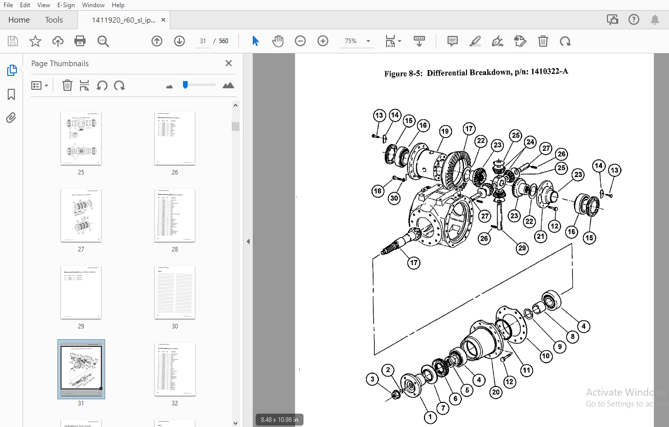
TABLE OF CONTENTS:
Drexel R60SL LPG Series Base IPB SwingMast Lift Truck Parts Manual 1411920 – PDF DOWNLOAD
General 8-11
Abbreviations 8-11
Phantoms / Reference Parts 8-11
Task Groups/Assemblies 8-11
Drive Axle Installation, DA326-A 8-14
Figure 8-1: Drive Axle Installation, DA326-A 8-15
LI-joint Installation, DA322 1-A 8-18
Figure 8-2: LI-joint Installation, DA322 1-A 8-19
Drive Axle, Modified, DA322-A 8-22
Figure 8-3: Drive Axle, Modified, DA322-A 8-23
Disk Brake Service, p/n: 1415954-A 8-24
Figure 8-4: Disk Brake Service, p/n: 1415954-A 8-25
Differential Breakdown, p/n: 1410322-A 8-26
Differential Breakdown, p/n: 1410322-A (continued) 8-27
Figure 8-5: Differential Breakdown, p/n: 1410322-A 8-29
Axle Breakdown, p/n: 1415946-A 8-30
Axle Breakdown, p/n: 1415946-A (Continued) 8-31
Figure 8-6: Axle Breakdown, p/n: 1415946-A 8-33
Housing and Covers, Service, p/n: 1415933-A 8-34
Figure 8-7: Housing and Covers, Service, p/n: 1415933-A 8-35
Master Cylinder Tube Installation, DA469-A 8-38
Figure 8-8: Master Cylinder Tube Installation, DA469-A 8-39
D A Brake Tube Installation, DA324-A 8-42
Figure 8-9: D A Brake Tube Installation, DA324-A 8-43
Park Brake Cable Connection, DA481-A 8-46
Figure 8-10: Park Brake Cable Connection, DA481-A 8-47
Brake Pedal Sub-Assembly, OH467-C 8-50
Figure 8-11: Brake Pedal Sub-Assembly, OH467-C 8-51
Brake Linkage Installation, OH396-B 8-54
Figure 8-12: Brake Linkage Installation, OH396-B 8-55
Master Cylinder, Brake, p/n: 1407337-A 8-56
Figure 8-13: Master Cylinder, Brake, p/n: 1407337-A 8-56
Brake Line Installation, OH405-B 8-58
Figure 8-14: Brake Line Installation, OH405-B 8-59
Park Brake Installation, DA326 1-A 8-62
Figure 8-15: Park Brake Installation, DA326 1-A 8-63
Park Brake Installation, OH391-B 8-66
Figure 8-16: Park Brake Installation, OH391-B 8-67
Park Brake Switch Assembly, OH465-8 8-70
Figure 8-17: Park Brake Switch Assembly, OH465-8 8-71
Steer Axle Installation, SA478-A : 8-74
Figure 8-18: Steer Axle Installation, SA478-A 8-75
Steer Axle Assembly, p/n: 1407432-D ; 8-76
Figure 8-19: Steer Axle Assembly, p/n: 1407432-D (sheet 1 of 2) 8-77
Figure 8-20: Steer Axle Assembly, p/n: 1407432-D (sheet 2 of 2) 8-79
Steering Cylinder, p/n: 2805184-A ‘ 8-80
Figure 8-21: Steering Cylinder, p/n: 2805184-A 8-81
Axle Oscillation Pad Installation, SA457-A , 8-83
Figure 8-22: Axle Oscillation Pad Installation, SA457-A 8-83
Front Tires and Nuts, p/n: DA362 1-8 ; 8-86
Figure 8-23: Front Tires and Nuts, p/n: DA362 1-8 8-87
Wheel and Tire Assembly, pin: 1404928-A 8-88
Figure 8-24: Wheel and Tire Assembly, p/n: 1404928-A 8-88
Wheel and Tire Assembly, p/n: 1404929-A 8-89
Figure 8-25: Wheel and Tire Assembly, p/n: 1404929-A 8-89
Rear Tires and Nuts, SA361-A 8-91
Figure 8-26: Rear Tires and Nuts, SA361-A 8-91
Steering Tire and Wheel Assembly, pin: 1400854-8 8-92
Figure 8-27: Steering Tire and Wheel Assembly, pin: 1400854-8 8-92
Drive Tire Nut Re-torque, IA492-E : 8-94
Figure 8-28: Drive Tire Nut Re-torque, IA492-E ‘ 8-95
Accelerator Pedal Assembly, OH476-C 8-97
Figure 8-29: Accelerator Pedal Assembly, OH476-C 8-97
Accelerator Cable Installation, OH404-A 8-100
Figure 8-30: Accelerator Cable Installation, OH404-A 8-101
Silicone Insulation Pins, OH392 1-A 8-103
Figure 8-31: Silicone Insulation Pins, OH392 1-A 8-103
Front Engine Mount Sub-Assembly, ET314-A 8-106
Figure 8-32: Front Engine Mount Sub-Assembly, ET314-A 8-107
Engine Mount Installation, ET315-A 8-110
Figure 8-33: Engine Mount Installation, ET315-A 8-111
Engine and Transmission Mounting, ET356-A , 8-114
Figure 8-34: Engine and Transmission Mounting, ET356-A 8-115
Engine/Transmission Sub-Installation, ET441 1-A 8-118
Figure 8-35: Engine/Transmission Sub-Installation, ET441 1-A 8~119
8-2 R60SL LPG Serles, Base unit, p/n: 1411920-e, Serfal #: 100 & Before, 10/01
Engine/Transmission Mount Installation, ET341 5-A 8-122
Figure 8-36: Engine/Transmission Mount Installation ET341 5-A 8-123
Regulator Installation, ET443 2-A 8-126
Figure 8-37: Regulator Installation, ET 443 2-A 8-127
Eng /Trans Component Installation, ET415 1-A 8-130
Figure 8-38: Eng !Trans Component Installation, ET415 1-A 8-131
Inch Bracket Installation, ET352-A 8-134
Figure 8-39: Inch Bracket Installation, ET352-A 8-135
Transmission Filter Lines Installation, ET474-A 8-138
Figure 8-40: Transmission Filter Lines Installation, ET474-A 8-139
Transmission Remote Filter, ET345 3-A 8-142
Figure 8-41: Transmission Remote Filter, ET345 3-A 8-143
Hydraulic Pump Sub-Assembly, ET440-A : 8-146
Figure 8-42: Hydraulic Pump Sub-Assembly, ET440-A 8-147
Tandem Gear Pump Service, p/n: 1409398-A 8-149
Figure 8-43: Tandem Gear Pump Service, p/n: 1409398-A 8-149
Transmission Drain Port Line, ET450-A 8-152
Figure 8-44: Transmission Drain Port Line, ET450-A 8-153
Dipstick Installation, ET353 1-A 8-156
Figure 8-45: Dipstick Installation, ET353 1-A 8-157
Transmission Installation, ET501-A 8-160
Figure 8-46: Transmission Installation, ET501-A 8-161
Torque Converter Installation, ET346 1-A , 8-164
Figure 8-47: Torque Converter Installation, ET346 1-A 8-165
Air Intake Hose Bracket, ET502-A 8-168
Figure 8-48: Air Intake Hose Bracket, ET502-A 8-169
Engine Filter Lines Installation, ET345 6-A 8-172
Figure 8-49: Engine Filter Lines Installation, ET345 6-A 8-173
Engine Sump Drain, ET507-A 8-176
Figure 8-50: Engine Sump Drain, ET507-A 8-177
Alternator Installation, ET443 1-A 8-180
Figure 8-51: Alternator Installation, ET443 1-A 8-181
Accelerator Lever Adjustment, ET351 1-A 8-184
Figure 8-52: Accelerator Lever Adjustment, ET351 1-A 8-185
Engine Fuel Adjustment, p/n: ET351 9-A 8-187
Figure 8-53: Engine Fuel Adjustment, p/n: ET351 9-A 8-187
Battery Tray Installation, p/n: EL370 1 8-190
Figure 8-54: Battery Tray Installation, p/n: EL370 1 8-191
Battery Cable Installation, p/n: EL307 8-194
Figure 8-55: Battery Cable Installation, p/n: EL307 8-195
RB0SL LPG Serles, Base unit, p/n: 1411920-e, Serial#: 100 & Before, 10/01 8-3
Air Filter Installation, Al340-A 8-198
Figure 8-56: Air Filter Installation, Al340-A 8-199
Fuel System Installation, FG504 , 8-202
Cooling Hose Installation, CG500-A 8-206
Figure 8-58: Cooling Hose Installation, CG500 8-207
Radiator Installation, p/n: CG503-A : 8-210
Figure 8-59: Radiator Installation, p/n: CG503-A 8-211
Cooling Hoses Installation, CG506-A 8-214
Figure 8-60: Cooling Hoses Installation, CG506 8-215
Overflow Hose Installation, CG508-A 8-218
· Figure 8-61: Overflow Hose Installation, CG508-A 8-219
Muffler Installation, EX310 8-222
Figure 8-62: Muffler Installation, EX310 8-223
Filter Tray Sub-Assembly Installation, FT305 1-A 8-226
Figure 8-63: Filter Tray Sub-Assembly Installation, FT305 1-A 8-227
Filter Tray Sub-Assembly, FT376 1 8-230
Figure 8-64: Filter Tray Sub-Assembly FT376 1 8-231
Engine Oil Filter Sub-Assembly, FT387 1 , 8-234
Figure 8-65: Engine Oil Filter Sub-Assembly, FT387 1 8-235
Transmission Filter Sub-Assembly, FT388-A : 8-238
Figure 8-66: Transmission Filter Sub-Assembly, FT388-A 8-239
Dash Panel Installation, p/n: OH380 3-A 8-242
Figure 8-67: Dash Panel Installation, p/n: OH380 3-A 8-243
Instrument Panel Assembly, p/n: 1411987-0 8-244
Instrument Panel Assembly, p/n: 1411987-D (continued) 8-245
Figure 8-68: Instrument Panel Assembly, pin: 1411987-D 8-247
Console Installation, OH420 8-250
Figure 8-69: Console Installation, OH420 8-251
Console Sub-Assembly, OH389-C 8-254
Figure 8-70: Console Sub-Assembly, OH389-C 8-255
Wire, Wheel Installation, OH384-D 8-258
Figure 8-71: Wire, Wheel Installation, OH384-D 8-259
Orbitrol Installation, OH403-8 : 8-262
Figure 8-72: Orbitrol Installation, OH403-8 8-263
Orbitrol Sub-Assembly, OH365-8 8-266
Figure 8-73: Orbitrol Sub-Assembly, OH365-8 8-267
Steering Control Unit, p/n: 1404339-8 8-268
Figure 8-74: Steering Control Unit, p/n: 1404339-8 8-269
8-4 R60SL LPG Serles, Base unit, pin: 1411920-e, Serlal #: 100 & Before, 10/01
Steering Column Installation, OH422-D 8-272
Figure 8-75: Steer Column Installation, OH422-D 8-273
Steer Column Sub-Assembly, p/n: OH399 2-A 8-276
Figure 8-76: Steer Column Sub-Assembly, p/n: OH399 2-A 8-277
Steering Lines Frame Installation, HY338-C 8-280
Figure 8-77: Steering Lines Frame Installation, HY338-C 8-281
Steer Lines Rear Installation, HY339 1 8-284
Figure 8-78: Steer Lines Rear Installation, HY339 1 8-285
Horn Installation, EL373 1-A 8-288
Figure 8-79: Horn Installation, EL373 1-A 8-289
Joystick Installation, OH402-B 8-291
Figure 8-80: Joystick Installation, OH402-B 8-291
Joystick Assembly, OH378-B 8-294
Figure 8-81: Joystick Assembly, OH378-B 8-295
Joystick Cable to Valve, OH381-D 8-298
Figure 8-82: Joystick Cable to Valve, OH381-D 8-299
Seat Installation, OH397-F 8-302
Figure 8-83: Seat Installation, OH397-F 8-303
Fuse Panel Door Installation, OH395 1-B 8-306
Figure 8-84: Fuse Panel Door Installation, OH395 1-B 8-307
Fuse Panel Door Assembly, p/n: 1410127-A 8-308
Figure 8-85: Fuse Panel Door Assembly, p/n: 1410127-A 8-309
Wire Harness Routing, Front, EL373-A 8-312
Figure 8-86: Wire Harness Routing, Front, EL373-A 8-313
Wire Harness, Left Side, EL451 8-316
Figure 8-87: Wire Harness – Left Side, EL451 8-317
Wire Harness Installation, p/n: EL430 2-A 8-320
Figure 8-88: Wire Harness Installation, p/n: EL430 2-A 8-321
Overhead Guard Ground Installation, EL431 1 8-324
Figure 8-89: Overhead Guard Ground Installation, EL431 1 8-325
Fluids and Lubricants, FL448 8-328
Figure 8-90: Fluids and Lubricants, FL448 8-329
Hydraulic Tank Installation, HY309-D 8-332
Figure 8-91: Hydraulic Tank Installation, HY309-D 8-333
Hydraulic Tank Assembly, p/n: 1414745-A 8-334
Figure 8-92: Hydraulic Tank Assembly, p/n: 1414745-A 8-335
Drain Lines Installation, HY318-B 8-338
Figure 8-93: Drain Lines Installation, HY318-B 8-339
R60SL LPG Serles, Base unit, pin: 1411920-e, Serlal #: 100 & Before, 10/01 8-5
Drain Plate Sub-Assembly, HY317-B 8-341
Figure 8-94: Drain Plate Sub-Assembly, HY317-8 8-341
Valve to Manifold Hose Installation, HY303-D 8-344
Figure 8-95: Valve to Manifold Hose Installation, HY303-D 8-345
Stack Valve, Low Hose Installation, HY304-C 8-348
Figure 8-96: Stack Valve, Low Hose Installation, HY304-C 8-349
Filter Assembly, 10 Micron, p/n: 1408618-A 8-350
Figure 8-97: Filter Assembly, 10 Micron, p/n: 1408618-A 8-350
Stack Valve Installation, HY416-8 8-352
Figure 8-98: Stack Valve Installation, HY416-B 8-353
Control Valve Assembly, p/n: 1410228-A 8-354
Figure 8-99: Control Valve Assembly, p/n: 1410228-A 8-355
Valve Spool, 4 Function, p/n: 1408724-A 8-356
Valve Spool, 4 Function, p/n: 1408724-A (Continued) : 8-357
Figure 8-100: Valve Spool, 4 Function, p/n: 1408724-A 8-359
Hydraulic Hose Installation, HY325-A 8-362
Figure 8-101: Hydraulic Hose Installation, HY325-A 8-363
Hydraulic Hose Routing, HY310-A 8-366
Figure 8-102: Hydraulic Hose Routing, HY310-A 8-367
Umbilical Manifold Installation, HY368 2-C 8-370
Figure 8-103: Umbilical Manifold Installation, HY368 2°C 8-371
Umbilical Assembly, p/n: 1409002-8 8-372
Figure 8-104: Umbilical Assembly, p/n: 1409002-8 8-373
Pivot and Shift Installation, PS437-A 8-376
Figure 8-105: Pivot and Shift Installation, PS437-A 8-377
Pivot Manifold Installation, PS471-A 8-380
Figure 8~106: Pivot Manifold Installation, PS471-A 8-381
Pivot Cylinder Installation, PS426-A 8-384
Figure 8-107: Pivot Cylinder Installation, PS426-A 8-385
Pivot Cylinder Breakdown, p/n: 1407231-A 8-386
Figure 8-108: Pivot Cylinder Breakdown, pin: 1407231-A 8-387
Pivot and Shift Hose Installation, PS436-A : 8-390
Figure 8-109: Pivot and ShiftHose Installation, PS436-A 8-391
Pivot, Shift and Tilt Lines, PS442-A 8-394
Figure 8-110: Pivot, Shift and Tilt Lines, PS442-A 8-395
Tilt Cylinder Line Installation, PS473-A 8-398
Figure 8-111: Tilt Cylinder Line Installation, PS473-A 8-399
Pivot Seal Installation, PS419-A 8-402
Figure 8-112: Pivot Seal Installation, PS419-A 8-403
Mast Lines Installation, Lower, PS447-A 8-406
Figure 8-113: Mast Lines Installation, Lower, PS447-A 8-407
8-6 R60SL LPG Series, Base unit, pin: 1411920-e, Serial#: 100 & Before, 10/01
Roller Bearing Cup Installation, PS417 1-A 8-409
Figure 8-114: Roller Bearing Cup Installation, PS417 1-A 8-409
Radial Bushing Installation, PS417-A 8-412
Figure 8-115: Radial Bushing Installation, PS417-A 8-413
Pivot Bearing Installation, PS419 1-A 8-416
Figure 8-116: Pivot Bearing Installation, PS419 1-A 8-417
Tilt Cylinder Assembly, p/n: TG1003-A 8-420
Figure 9: Tilt Cylinder Assemblies, p/n: TG1003-A 8-421
Tilt Cylinder Breakdown, p/n: 1410606-A 8-422
Figure 10: Tilt Cylinder Breakdown, p/n: 1410606-A 8-423
Fixed Side Shift Chain Installation, PS425-A 8-426
Figure 8-1: Fixed Side Shift Chain Installation, PS425-A 8-427
Yoke and Chain Sheave Sub-Assembly, PS428-A 8-430
Figure 8-2: Yoke and Chain Sheave Sub-Assembly, PS428-A 8-431
Side Shift Cylinder Installation, PS423-A 8-434
Figure 8-3: Side Shift Cylinder Installation, PS423-A 8-435
Shift Cylinder Breakdown, p/n: 1400006-B 8-436
Figure 8-4: Shift Cylinder Breakdown, p/n: 1400006-B 8-437
Side Shift Bearing Installation, PS432-A 8-440
Figure 8-5: Side Shift Bearing Installation, PS432-A 8-441
Cross head Pivot Arm Installation, PS429-A 8-444
Figure 8-6: Crosshead Pivot Arm Installation, PS429-A 8-445
Bearing Assembly, PS421-A 8-448
Figure 8-7: Bearing Assembly, PS421-A 8-449
Side Shift Roller Bearing Installation, PS432 1-A 8-452
Figure 8-8: Side Shift Roller Bearing Installation, PS432 1-A 8-453
Stop Block Installation, PS434-A 8-456
Figure 8-9: Stop Block Installation, PS434-A 8-457
Overhead Guard Installation, OH468-B 8-460
Figure 8-10: Overhead Guard Installation, OH468-B 8-461
Overhead Guard Installation, OH377 2-A 8-463
Figure 8-11: Overhead Guard Installation OH377 2-A 8-463
Overhead Guard Sub-Assembly, OH487-B 8-466
Figure 8-12: Overhead Guard Sub-Assembly, OH487-B 8-467
Overhead Guard Foam Installation, OH488-A 8-470
Figure 8-13: Overhead Guard Foam Installation, OH488-A 8-471
Floor Plate Installation, OH490-A 8-474
Figure 8-14: Floor Plate Installation, OH490-A : 8-475
R60SL LPG Serles, Base unit, pin: 1411920 ~e, Serial#: 100 & Before, 10/01 8-7
Access Door Installation, OH491-A 8-478
Figure 8-15: Access Door Installation, OH491-A 8-479
Fuel Outlet Covers, OH489 : 8-482
Figure 8-16: Fuel Outlet Covers; OH489 8-483
Rear View Mirror Installation, OH512-A 8-486
Figure 8-17: Rear View Mirror Installation, OH512-A 8-487
Front and Rear Floods Lights, p/n: EL 1550-A 8-489
Figure 8-18: Front and Rear Floods Lights, p/n: EL 1550-A 8-489
Flood Lamp Modification, p/n: 1409039-D 8-490
Figure 8-19: Flood Lamp Modification, p/n: 1409039-D 8-491
Mast Flood Light Option, EL 1501-A 8-494
Replacement Bulb and Lens , 8-494
Figure 9-20: Mast Flood Light Option, EL 1501-A 8-495
Front and Rear Flood Lights, EL 1504-A 8-498
Replacement Bulb and Lens 8-498
Figure 9-21: Front and Rear Flood Lights, EL 1504-A 8-499
Strobe Light, Blue, pin: EL 1508-A 8-502
Figure 8-22: Strobe Light, Blue, p/n: EL 1508-A 8-503
Strobe Light Breakdown, p/n: 1414451-A 8-504
Figure 8-23: Strobe Light Breakdown, p/n: 1414451-A 8-504
Brake and Tail Light Installation, OH379-C 8-506
Figure 8-24: Brake and Tail Light Installation, OH379-C 8-507
Lamp, Single Bulb, p/n: 28789-A 8-508
Figure 8-25: Lamp, Single Bulb, p/n: 28789-A 8-508
Fire Extinguisher Installation, FE416-A , 8-510
Figure 9: Fire Extinguisher Installation, FE416-A 8-511
Lower Counterweight Installation, CT311 1 8-514
Figure 8-1: Lower Counterweight Installation, CT311 1 8-515
Side Counterweight Installation, CT335sA 8-518
Figure 8-2: Side Counterweight Installation, CT335-A 8-519
Rear Counterweight Sub-Assembly, CT337 8-522
Figure 8-3: Rear Counterweight Sub-Assembly, CT337 8-523
Rear Counterweight Installation, CT359 8-526
Figure 8-4: Rear Counterweight Installation, CT359 8-527
Rear Counterweight Bar Installation, CT505 8-529
Figure 8-5: Rear Counterweight Bar Installation, CT505 8-529
Rear Cover Installation, CO360 8-532
Figure 8-6: Rear Cover Installation, CO360 8-533
8-8 R60SL LPG Serles, Base unit, p/n: 1411920 -e, Serial#: 100 & Before, 10/01
Side Cover and Hood Installation, CO363-A 8-536
Figure 8-7: Side Cover and Hood Installation, CO363-A 8-537
Standard “Yellow” Paint, PA1401-A 8-539
Mast Installation, p/n: MA1215-A 8-542
Figure 8-8: Mast Installation, p/n: MA1215-A 8-543
Mast Adjustment, IA480-A 8-545
Figure 8-9: Mast Adjustment, IA480-A : 8-545
Front End Adjustment, IA479 8-547
Figure 8-10: Front End Adjustment, IA479 (Sheet 1 of 2) 8-548
Figure 8-11: Front End Adjustment, IA479 (Sheet 2 of 2) 8-549
Lower Cam Sub-Assembly, OH466-C 8-551
Figure 8-12: Lower Cam Sub-Assembly, OH466-C 8-551
Fork Installation, p/n: OP1108 -A 8-553
ID Group, Decals, p/n: ID983 2-A 8-555
ID Group, Decals, p/n: ID983 2-A 8-556
Figure 8-13: ID Group, Decals, p/n: ID983 2-A 8-557
More products