$40
Drexel R60SL LPG Series Base IPB SwingMast Lift Truck Parts Manual 1411920 – PDF DOWNLOAD
Drexel R60SL LPG Series Base IPB SwingMast Lift Truck Parts Manual 1411920 – PDF DOWNLOAD
FILE DETAILS:
Drexel R60SL LPG Series Base IPB SwingMast Lift Truck Parts Manual 1411920 – PDF DOWNLOAD
Language : English
Pages : 532
Downloadable : Yes
File Type : PDF
IMAGES PREVIEW OF THE MANUAL:
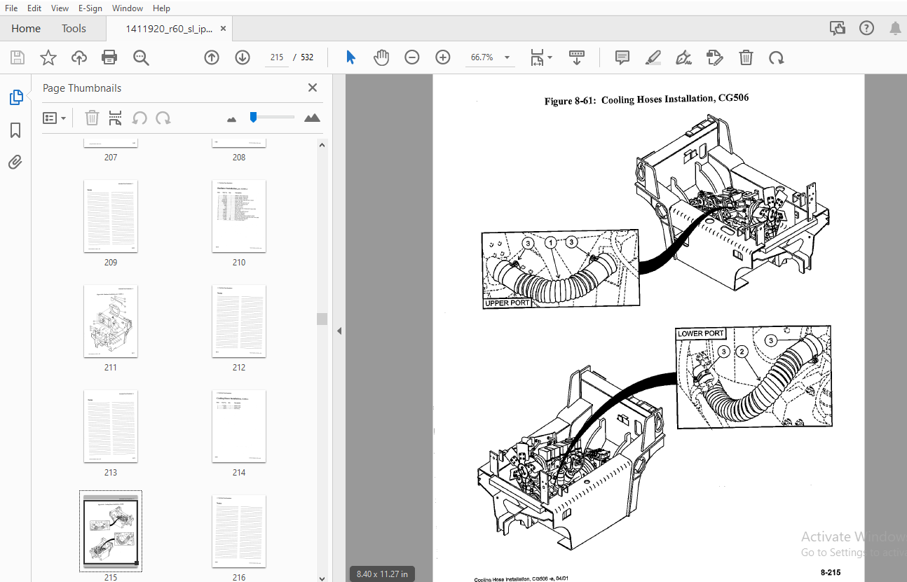
TABLE OF CONTENTS:
Drexel R60SL LPG Series Base IPB SwingMast Lift Truck Parts Manual 1411920 – PDF DOWNLOAD
General 8-13
Abbreviations 8-13
Phantoms / Reference Parts 8-13
Task Groups/Assemblies 8-13
Drive Axle Installation, DA326-A 8-16
Figure 8-1: Drive Axle Installation, DA326-A 8-17
Drive Axle Modification, p/n: DA17-A 8-20
Figure 8-2: Drive Axle Modification, p/n: DA17-A 8-21
Housing Service Kit, p/n: 1415933-A 8-23
Figure 8-3: Service Kit, Housing and p/n: 1415933 -A 8-23
Differential Breakdown, p/n: 1410322-A (standard) 8-24
Figure 8-4: Differential Breakdown, p/n: 1410322-A (standard) 8-25
Differential Service Kit, p/n: 1420722-A (Home Depot) 8-26
Figure 8-5: Differential Service Kit, p/n: 1420722-A 8-27
Disk Brake Service Kit, pin: 1415954-A 8-28
Figure 8-6: Disk Brake Service Kit, p/n: 1415954-A 8-29
U-Joint Installation, p/n: DA18 -A 8-31
Figure 8-7: U-Joint Installation, p/n: DA18 -A 8-31
Master Cylinder Tube Installation, DA469-A 8-34
Figure 8-8: Master Cylinder Tube Installation, DA469-A 8-35
D A Brake Tube Installation, DA324-A 8-38
Figure 8-9: D A Brake Tube Installation, DA324-A 8-39
Park Brake Cable Connection, DA481-A 8-42
Figure 8-10: Park Brake Cable Connection, DA481-A 8-43
Brake Pedal Sub-Assembly, OH467-C 8-46
Figure 8-11: Brake Pedal Sub-Assembly, OH467-C 8-47
Brake Linkage Installation, OH396-B 8-50
Figure 8-12: Brake Linkage Installation, OH396-B 8-51
Master Cylinder, Brake, p/n: 1407337-A 8-52
Figure 8-13: Master Cylinder, Brake, p/n: 1407337-A 8-52
Brake Line Installation, OH405-B 8-54
Figure 8-14: Brake Line Installation, OH405-B 8-55
Park Brake Installation, DA326 1-A 8-58
Figure 8-15: Park Brake Installation, DA326 1-A 8-59
Park Brake Installation, OH391-B 8-62
Figure 8-16: Park Brake Installation, OH391-B 8-63
Park Brake Switch Assembly, OH465-8 8-66
Figure 8-17: Park Brake Switch Assembly, OH465-B 8-67
Steer Axle Installation, SA478-A 8-70
Figure 8-18: Steer Axle Installation, SA478-A 8-71
Steer Axle Assembly, p/n: 1407432-D 8-72
Figure 8-19: Steer Axle Assembly, p/n: 1407432-D (sheet 1 of 2) 8-73
Figure 8-20: Steer Axle Assembly, pin: 1407432-D (sheet 2 of 2) 8-75
Steering Cylinder, p/n: 2805184-A 8-76
Figure 8-21: Steering Cylinder, p/n: 2805184-A 8-77
Axle Oscillation Pad lnstallation,SA457-A 8,79
Figure 8-22: Axle Oscillation Pad Installation, SA457-A 8-79
Front Tires and Nuts, p/n: DA362 1-B 8-82
Figure 8-23: Front Tires and Nuts, p/n: DA362 1-B 8-83
Wheel and Tire Assembly, p/n: 1404928-A 8-84
Figure 8-24: Wheel and Tire Assembly, p/n: 1404928-A 8-84
Wheel and Tire Assembly, p/n: 1404929-A 8-85
Figure 8-25: Wheel and Tire Assembly, p/n: 1404929-A 8-85
Rear Tires and Nuts, SA361-A 8-87
Figure 8-26: Rear Tires and Nuts, SA361-A , 8-87
Steering Tire and Wheel Assembly, p/n: 1400854-8 8-88
Figure 8-27: Steering Tire and Wheel Assembly, p/n: 1400854-B 8-88
Drive Tire Nut Re-torque, IA492-E • 8-90
Figure 8-28: Drive Tire Nut Re-torque, IA492-E 8-91
Accelerator Pedal Assembly, OH476-C 8-93
Figure 8-29: Accelerator Pedal Assembly, OH476-C 8-93
Accelerator Cable Installation, OH404-A 8-96
Figure 8-30: Accelerator Cable Installation, OH404-A ; 8-97
Silicone Insulation Pins, OH392 1-A 8-99
Figure 8-31: Silicone Insulation Pins, OH392 1-A 8-99
Front Engine Mount Sub-Assembly, ET314-A 8-102
Figure 8-32: Front Engine Mount Sub-Assembly, ET314-A 8-103
Engine Mount Installation, ET315-A 8-106
Figure 8-33: Engine Mount Installation, ET315-A 8-107
Engine and Transmission Mounting, ET356-A 8-110
Figure 8-34: Engine and Transmission Mounting, ET356-A 8-111
Engine/Transmission Sub-Installation, ET441 1-A 8-114
Figure 8-35: Engine/Transmission Sub-Installation, ET441 1-A 8-115
Engine/Transmission Mount Installation, ET341 5-A 8-118
Figure 8-36: Engine/Transmission Mount Installation ET341 5-A 8-119
Regulator Installation, ET443 2-A 8-122
Figure 8-37: Regulator Installation, ET443 2-A 8-123
Eng /Trans Component Installation, ET415 1-A 8-126
Figure 8-38: Eng /Trans Component Installation, ET415 1-A 8-127
Inch Bracket Installation, ET352-A 8-130
Figure 8-39: Inch Bracket Installation, ET352-A 8-131
Engine Shutdown System, p/n: ET12-A 8-134
Figure 8-40: Engine Shutdown System, pin: ET12-A 8-135
Transmission Filter Lines Installation, ET474-A 8-138
Figure 8-41: Transmission Filter Lines Installation, ET474-A 8-139
Transmission Remote Filter, ET345 3-A 8-142
Figure 8-42: Transmission Remote Filter, ET345 3-A 8-143
Hydraulic Pump Sub-Assembly, ET440-A 8-146
Figure 8-43: Hydraulic Pump Sub-Assembly, ET440-A 8-147
Tandem Gear Pump Service, p/n: 1409398-A 8-149
Figure 8-44: Tandem Gear Pump Service, p/n: 1409398-A 8-149
Transmission Drain Port line, ET450-A 8-152
Figure 8-45: Transmission Drain Port Line, ET450-A 8-153
Dipstick Installation, ET353 1-A 8-156
Figure 8-46: Dipstick Installation, ET353 1-A 8-157
Transmission Installation, ET501-A 8-160
Figure 8-47: Transmission Installation, ET501-A 8-161
Torque Converter Installation, ET346 1-A 8-164
Figure 8-48: Torque Converter Installation, ET346 1-A 8-165
Air Intake Hose Bracket, ET502-A 8-168
Figure 8-49: Air Intake Hose Bracket, ET502-A 8-169
Engine Filter Lines Installation, ET345 6-A 8-172
Figure 8-50: Engine Filter Lines Installation, ET345 6-A 8-173
Engine Sump Drain, ET507-A 8-176
Figure 8-51: Engine Sump Drain, ET507-A 8-177
Alternator Installation, ET443 1-A 8-180
Figure 8-52: Alternator Installation, ET443 1-A 8-181
Accelerator Lever Adjustment, ET351 1-A 8-184
Figure 8-53: Accelerator Lever Adjustment, ET351 1-A 8-185
Engine Fuel Adjustment, p/n: ET351 9-A 8-187
Figure 8-54: Engine Fuel Adjustment, p/n: ET351 9-A 8-187
Battery Tray Installation, p/n: EL370 1 8-190
Figure 8-55: Battery Tray Installation, p/n: EL370 1 8-191
Battery Cable Installation, p/n: EL307 8-194
Figure 8-56: Battery Cable Installation, p/n: EL307 8-195
Air Filter Installation, Al340-A 8-198
Figure 8-57: Air Filter Installation, Al340-A 8-199
Fuel System Installation, p/n: FG1-A • 8-202
Figure 8-58: Fuel System Installation, p/n: FG1-A 8-203
Cooling Hose Installation, CG500-A 8-206
Figure 8-59: Cooling Hose Installation, CG500 , 8-207
Radiator Installation, p/n: CG503-A • , 8-210
Figure 8-60: Radiator Installation, p/n: CG503-A 8-211
Cooling Hoses Installation, CG506-A 8-214
Figure 8-61: Cooling Hoses Installation, CG506 , 8-215
Overflow Hose Installation, CG508-A 8-218
Figure 8-62: Overflow Hose Installation, CG508-A 8-219
Muffler Installation, EX310 8-222
Figure 8-63: Muffler Installation, EX310 8-223
Filter Tray Sub-Assembly Installation, FT305 1-A 8-226
Figure 8-64: Filter Tray Sub-Assembly Installation, FT305 1-A 8-227
Filter Tray Sub-Assembly, FT376 1 8-230
Figure 8-65: Filter Tray Sub-Assembly FT376 1 8-231
Engine Oil Filter Sub-Assembly, FT387 1 8-234
Figure 8-66: Engine Oil Filter Sub-Assembly, FT387 1 • 8-235
Transmission Filter Sub-Assembly, FT388-A , 8-238
Figure 8-67: Transmission Filter Sub-Assembly, FT388-A 8-239
Dash Panel Installation, p/n: OH30-A 8-242
Figure 8-68: Dash Panel Installation, p/n: OH30-A 8-243
Instrument Panel Assembly, p/n: 1420733-A 8-244
Instrument Panel Assembly, p/n: 1420733-A (continued) 8-245
Figure 8-69: Instrument Panel Assembly, p/n: 1420733-A , 8-247
Console Installation, p/n: OH32-A 8-249
Figure 8-70: Console Installation, p/n: OH32-A • 8-249
Console Sub-Assembly, p/n: OH31-A , 8-252
Figure 8-71: Console Sub -Assembly, p/n: OH31-A 8-253
Wire, Wheel Installation, OH384-D : 8-256
Figure 8-72: Wire, Wheel Installation, OH384-D 8-257
Orbitrol Installation, OH403-B 8-260
Figure 8-73: Orbitrol Installation, OH403-B 8-261
Orbitrol Sub-Assembly, OH365-B 8-264
Figure 8-74: Orbitrol Sub-Assembly, OH365-B 8-265
Steering Control Unit, p/n: 1404339-B 8-266
Figure 8-75: Steering Control Unit, p/n: 1404339-8 8-267
Steering Column Installation, OH422-D 8-270
Figure 8-76: Steer Column Installation, OH422-D 8-271
Steer Column Sub-Assembly, pin: OH399 2-A 8-274
Figure 8-77: Steer Column Sub-Assembly, p/n: OH399 2-A 8-275
Steering Lines Frame Installation, HY338-C 8-278
Figure 8-78: Steering Lines Frame Installation, HY338-C 8-279
Steer Lines Rear Installation, HY339 1 8-282
Figure 8-79: Steer Lines Rear Installation, HY339 1 8-283
Horn Installation, EL373 1-A 8-286
Figure 8-80: Horn Installation, EL373 1-A 8-287
Joystick Installation, OH402-B 8-289
Figure 8-81: Joystick Installation, OH402-B 8-289
Joystick Assembly, OH378-B 8-292
Figure 8-82: Joystick Assembly, OH378-B 8-293
Joystick Cable to Valve, OH381-D 8-296
Figure 8-83: Joystick Cable to Valve, OH381-D 8-297
Seat Installation, OH397-F 8-300
Figure 8-84: Seat Installation, OH397-F 8-301 ·
Fuse Panel Door Installation, OH395 1-B 8-304
Figure 8-85: Fuse Panel Door Installation, OH395 1-B 8-305
Fuse Panel Door Assembly, p/n: 1410127-A 8-306
Figure 8-86: Fuse Panel Door Assembly, p/n: 1410127-A 8-307
Wire Harness Routing, Front, EL373-A 8-31 O
Figure 8-87: Wire Harness Routing, Front, EL373-A 8-311
Wire Harness, Left Side, EL451 8-314
Figure 8-88: Wire Harness – Left Side, EL451 8-315
Wire Harness Installation, p/n: EL430 2-A 8-318
Figure 8-89: Wire Harness Installation, p/n: EL430 2-A 8-319
Overhead Guard Ground Installation, EL431 1 8-322
Figure 8-90: Overhead Guard Ground Installation, EL431 1 8-323
Fluids and Lubricants, FL448 8-326
Figure 8-91: Fluids and Lubricants, FL448 8-327
Hydraulic Tank Installation, HY309-D 8-330
Figure 8-92: Hydraulic Tank Installation, HY309-D 8-331
Hydraulic Tank Assembly, p/n: 1414745-A 8-332
Figure 8-93: Hydraulic Tank Assembly, p/n: 1414745-A 8-333
Drain Lines Installation, HY318-B 8-336
Figure 8-94: Drain Lines Installation, HY318-B 8-337
Drain Plate Sub-Assembly, HY317-8 8-339
Figure 8-95: Drain Plate Sub-Assembly, HY317-B 8-339
Valve to Manifold Hose Installation, HY303-D 8-342
Figure 8-96: Valve to Manifold Hose Installation, HY303-D 8-343
Stack Valve, Low Hose Installation, HY304-C 8-346
Figure 8-97: Stack Valve, Low Hose Installation, HY304-C 8-347
Filter Assembly, 10 Micron, p/n: 1408618-A • 8-348
Figure 8-98: Filter Assembly, 10 Micron, p/n: 1408618-A 8-348
Stack Valve Installation, HY416-B 8-350
Figure 8-99: Stack Valve Installation, HY416-B 8-351
Control Valve Assembly, p/n: 1410228-A 8-352
Figure 8-100: Control Valve Assembly, p/n: 1410228-A 8-353
Valve Spool, 4 Function, p/n: 1408724-A 8-354
Valve Spool, 4 Function, p/n: 1408724-A (Continued) 8-355
Figure 8-101: Valve Spool, 4 Function, p/n: 1408724-A 8-357
Hydraulic Hose Installation, HY325-A 8-360
Figure 8-102: Hydraulic Hose Installation, HY325-A 8-361
Hydraulic Hose Routing, HY310-A 8-364
Figure 8-103: Hydraulic Hose Routing, HY310-A 8-365
Umbilical Manifold Installation, HY368 2-C 8-368
Figure 8-104: Umbilical Manifold Installation, HY368 2-C 8-369
Umbilical Assembly, p/n: 1409002-8 8-370
Figure 8-105: Umbilical Assembly, p/n: 1409002-8 8-371
Pivot and Shift Installation, PS437-A 8-374
Figure 8-106: Pivot and Shift Installation, PS437-A 8-375
Pivot Manifold Installation, PS471-A 8-378
Figure 8-107: Pivot Manifold Installation, PS471-A 8-379
Pivot Cylinder Installation, PS426-A 8-382
Figure 8-108: Pivot Cylinder Installation, PS426-A 8-383
Pivot Cylinder Breakdown, p/n: 1407231-A 8-384
Figure 8-109: Pivot Cylinder Breakdown, p/n: 1407231-A 8-385
Pivot and Shift Hose Installation, PS436-A 8-388
Figure 8c110: Pivot and Shift Hose Installation, PS436-A 8-389
Pivot, Shift and Tilt Lines, PS442-A 8-392
Figure 8-111: Pivot, Shift and Tilt Lines, PS442-A 8-393
Tilt Cylinder Line Installation, PS4 73-A 8-396
Figure 8-112: Tilt Cylinder Line Installation, PS473-A 8-397
Pivot Seal Installation, PS419-A • 8-400
Figure 8-113: Pivot Seal Installation, PS419-A 8-401
Mast Lines Installation, Lower, PS447-A 8-404
Figure 8-114: Mast Lines Installation, Lower, PS44 7-A 8-405
Roller Bearing Cup Installation, PS417 1-A 8-407
Figure 8-115: Roller Bearing Cup Installation, PS417 1-A 8-407
Radial Bushing Installation, PS417-A 8-410
Figure 8-116: Radial Bushing Installation, PS417-A 8-411
Pivot Bearing Installation, PS419 1-A 8-414
Figure 8-117: Pivot Bearing Installation, PS419 1-A 8-415
Tilt Cylinder Assembly, p/n: TG1003-A 8-418
Figure 9: Tilt Cylinder Assemblies, p/n: TG1003-A 8-419
Tilt Cylinder Breakdown, p/n: 1410606-A 8-420
Figure 10: Tilt Cylinder Breakdown, p/n: 1410606-A 8-421
Fixed Side Shift Chain Installation, PS425-A 8-424
Figure 8-1: Fixed Side Shift Chain Installation, PS425-A 8-425
Yoke and Chain Sheave Sub-Assembly, PS428-A 8-428
Figure 8-2: Yoke and Chain Sheave Sub-Assembly, PS428-A 8-429
Side Shift Cylinder Installation, PS423-A 8-432
Figure 8-3: Side Shift Cylinder Installation, PS423-A 8-433
Shift Cylinder Breakdown, p/n: 1400006-B 8-434
Figure 8-4: Shift Cylinder Breakdown, p/n: 1400006-B 8-435
Side Shift Bearing Installation, PS432-A 8-438
Figure 8-5: Side Shift Bearing Installation, PS432-A 8-439
Cross head Pivot Arm Installation, PS429-A 8-442
Figure 8-6: Crosshead Pivot Arm Installation, PS429-A 8-443
Bearing Assembly, PS421-A 8-446
Figure 8-7: Bearing Assembly, PS421-A 8-447
Side Shift Roller Bearing Installation, PS432 1-A 8-450
Figure 8-8: Side Shift Roller Bearing Installation, PS432 1-A 8-451
Stop Block Installation, PS434-A 8-454
Figure 8-9: Stop Block Installation, PS434-A 8-455
Overhead Guard Installation, OH468-B 8-458
Figure 8-10: Overhead Guard Installation, OH468-B 8-459
Overhead Guard Installation, OH377 2-A 8-461
Figure 8-11: Overhead Guard Installation OH377 2-A 8-461
Overhead Guard Sub-Assembly, OH487-B 8-4134
Figure 8-12: Overhead Guard Sub-Assembly, OH487-B 8-465
Overhead Guard Foam Installation, OH488-A 8-468
Figure 8-13: Overhead Guard Foam Installation, OH488-A 8-469
Floor Plate Installation, OH490-A 8-472
Figure 8-14: Floor Plate Installation, OH490-A 8-473
Access Door Installation, OH491-A 8-476
Figure 8-15: Access Door Installation, OH491-A 8-477
Fuel Outlet Covers, OH489 • • • 8-480
Figure 8-16: Fuel Outlet Covers, OH489 8-481
Rear View Mirror Installation, OH512-A 8-484
Figure 8-17: Rear View Mirror Installation, OH512-A 8-485
Front and Rear Floods Lights, p/n: EL 1550-A 8-487
Figure 8-18: Front and Rear Floods Lights, p/n: EL 1550-A 8-487
Flood Lamp Modification, p/n: 1409039-D 8-488
Figure 8-19: Flood Lamp Modification, p/n: 1409039-D 8-488
Mast Flood Light Option, EL 1501-A 8-490
Replacement Bulb and Lens 8-490
Figure 9-20: Mast Flood Light Option, EL 1501-A 8-491
Brake and Tail Light Installation, OH379-C 8-494
Figure 8-21: Brake and Tail Light Installation, OH379-C 8-495
Lamp, Single Bulb, p/n: 28789-A 8-496
Figure 8-22: Lamp, Single Bulb, p/n: 28789-A 8-496
Fire Extinguisher Installation, FE416-A 8-498
Figure 9: Fire Extinguisher Installation, FE416-A • 8-499
Rear Cover Installation, CO360 8-502
Figure 8-1: Rear Cover Installation, CO360 8-503
Side Cover and Hood Installation, CO363-A 8-506
Figure 8-2: Side Cover and Hood Installation, CO363-A , ,, 8-507
Standard “Yellow” Paint, PA 1401-A 8-509
Mast Installation, p/n: MA1215-A 8-512
Figure 8-3: Mast Installation, p/n: MA1215-A 8-513
Mast Adjustment, IA480-A 8-515
Figure 8-4: Mast Adjustment, IA480-A 8-515
Front End Adjustment, IA479 : 8-517
Figure 8-5: Front End Adjustment, IA479 {Sheet 1 of 2) 8-518
Figure 8-6: Front End Adjustment, IA4 79 (Sheet 2 of 2) 8-519
Lower Cam Sub-Assembly, OH466-C , 8-521
Figure 8-7: Lower Cam Sub-Assembly, OH466-C 8-521
Fork Installation, p/n: OP1108 -A 8-523
ID Group, Decals, p/n: ID983 2-A 8-525
ID Group, Decals, p/n: ID983 2-A 8-526
Figure 8-8: ID Group, Decals, p/n: ID983 2-A (sheet 1 of 2) 8-527
Figure 8-9: ID Group, Decals, p/n: ID983 2-A (sheet 2 of 2) 8-529
Schematics and Drawings 8-531
More products