$36
Drexel R60SL Standard Options IPB SwingMast Lift Truck Parts Manual 1416903 – PDF DOWNLOAD
Drexel R60SL Standard Options IPB SwingMast Lift Truck Parts Manual 1416903 – PDF DOWNLOAD
FILE DETAILS:
Drexel R60SL Standard Options IPB SwingMast Lift Truck Parts Manual 1416903 – PDF DOWNLOAD
Language : English
Pages : 212
Downloadable : Yes
File Type : PDF
IMAGES PREVIEW OF THE MANUAL:
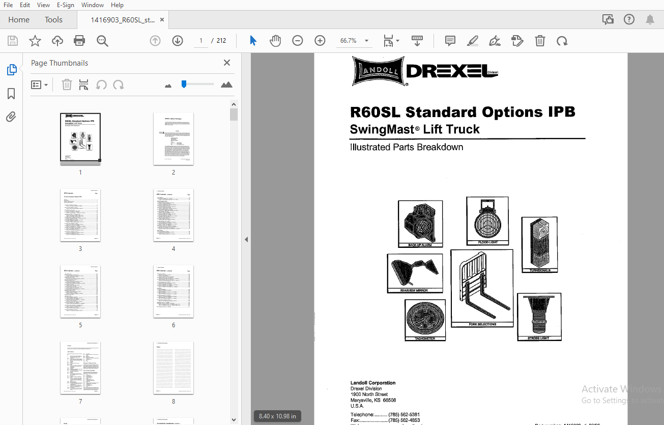
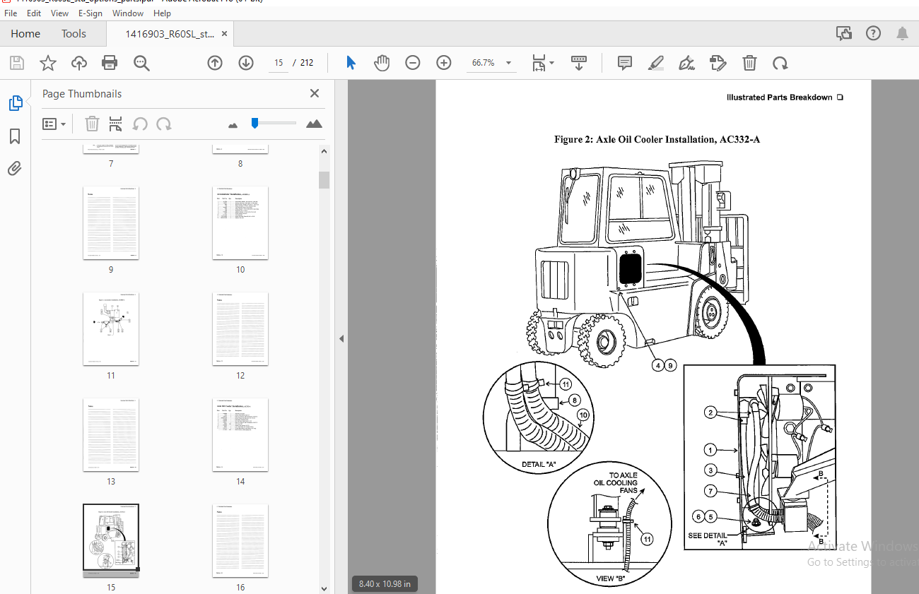
TABLE OF CONTENTS:
Drexel R60SL Standard Options IPB SwingMast Lift Truck Parts Manual 1416903 – PDF DOWNLOAD
R Series Standard Options IPB
General ?
Abbreviations 7
Phantoms / Reference Parts 7
Task Groups/Assemblies 7
Accumulator Installation, AO1802-A 10
Figure 1: Accumulator Installation, AO1802-A 11
Axle Oil Cooler Installation, AC332-A 14
Figure 2: Axle Oil Cooler Installation, AC332-A 15
Back Up Alarm – CBD, EL 1-A 18
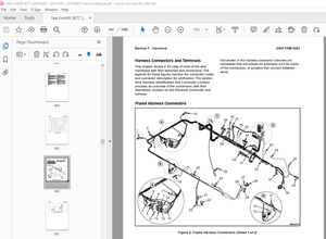
Figure 3: Back Up Alarm – CBD, EL 1-A 19
Back Up Alarm – LPG/Gas, p/n: EL 1506-A 22
Figure 8-1: Back Up Alarm – LPG/Gas, p/n: EL 1506-A 23
Dual Battery, DB1901-A (12V System Only) 26
Figure 9: Dual Battery, DB1901-A (sheet 1 of 2) 27
Figure 1 O: Dual Battery, DB 1901-A (sheet 2 of 2) 29
Dual Battery Option – LPG/Gas, p/n: EL58-A 32
Figure 8-1: Dual Battery Option – LPG/Gas, p/n: EL58-A 33
Battery Cable Installation, p/n: EL307 36
Figure 9: Battery Cable Installation, p/n: EL307 37
Battery Cables Installation, EL307 1-A 40
Figure 8-1: Battery Cables Installation, EL307 1-A 41
Drive Axle Pump Installation, AC349-A 44
Figure 9: Drive Axle Pump Installation, AC349-A 45
Centrifugal Pump, 12 Volts, p/n: 1408590-D 46
Figure 10: Centrifugal Pump, 12 Volts, p/n: 1408590-D 47
Centrifugal Pump Breakdown, p/n: 1407624-A 48
Figure 11: Centrifugal Pump Breakdown, p/n: 1407624-A 49
Drive Axle Guard Installation, AC357-A 52
Figure 12: Drive Axle Guard Installation, AC357-A 53
Fire Extinguisher Installation, FE416-A 56
Figure 13: Fire Extinguisher Installation, FE416-A 57
Fire Extinguisher Installation, FE417-B 60
Figure 14: Fire Extinguisher Installation, FE417-B 61
R60SL Serles, Standard Options, p/n: 1416903 -d, 08/03 Options -3
Fork Installation 63
Fork Positioner Installation, p/n: 1411230-A 66
Figure 15: Fork Positioner Installation, p/n: 1411230-A 67
Hydraulics, Single Function
Joystick Modification, SF1701-A 70
Figure 16: Joystick Modification, SF1701-A 71
Single Function Hydraulics, SF1702-A 74
Figure 17: Single Function Hydraulics, SF1702-A 75
Single Function Electrics, SF1703-A 78
Figure 18: Single Function Electrics, SF1703-A 79
Single Function Hose Block, SF1704-A 82
Figure 19: Single Function Hose Block, SF1704-A 83
S F Hoses to Mast Installation, p/n: HY27-A 86
Figure 20: S F Hoses to Mast Installation, p/n: HY27-A • 87
Lift Hose Installation, SF1705-A 90
Figure 21: Lift Hose Installation, SF1705-A 91
Control Valve Installation, SF1706-A 94
Figure 22: Control Valve Installation, SF1706-A 95
Control Valve Assembly, p/n: 1411461-A • 96
Figure 23: Control Valve Ass~mbly p/n: 1411461-A 97
Pivot and Shift Tilt Lines, SF1707-A 100
Figure 24: Pivot and Shift Tilt Lines, SF1707-A • , 101
Mast Tubes Installation, SF1708-A , 104
Figure 25: Mast Tubes Installation, SF1708-A , , 105
Standard Hydraulics, p/n: 1411491-D 108
Figure 26: Standard Hydraulics, p/n: 1411491-D 109
Control Valve Assembly, p/n: 1410228-A 110
Figure 27: Control Valve Assembly, p/n: 1410228-A 111
Valve Spool 4 Function, p/n: 1408724-A 112
Valve Spool 4 Function, p/n: 1408724-A (continued) 113
Figure 28: Valve Spool 4 Function p/n: 1408724 – A 115
Joystick Control, Pivot and Shift, p/n: 1407330-A , 116
Figure 29: Joystick Control, Pivot and Shift, p/n: 1407330-A 117
Light Packages
Strobe Light Option, p/n: EL53-A 120
Figure 30: Strobe Light Option, p/n: EL53-A 121
Strobe Light, Blue, p/n: 1414451-A 122
Figure 31: Strobe Light, Blue, p/n: 1414451-A 122
Options -4 R60SL Serles, Standard Options, p/n: 1416903 -d, 08/03
(12V System On/y) 124
Back-Up Light, Flashing “Red,” EL36-A 124
Figure 32: Backup Light, Flashing “Red,” EL36-A 125
Front and Rear Flood Lights, EL 1504-A 128
Replacement Bulb and Lens 128
Figure 33: Front and Rear Flood Lights, EL 1504-A , 129
Mast Flood Light Option, EL 1501-A 132
Replacement Bulb and Lens 132
Figure 34: Mast Flood Light Option, EL 1501-A 133
Flood Light Bracket Installation, EL 1503-B 136
Figure 35: Flood Light Bracket Installation, EL 1503-B 137
Strobe Light, Cab, EL33-A 140
Figure 36: Strobe Light, Cab, EL33-A 141
Strobe Light, Blue, p/n: EL 1508-A 144
Figure 37: Strobe Light, Blue, p/n: EL 1508-A 145
Strobe Light Breakdown, p/n: 1414451-A 146
Figure 38: Strobe Light Breakdown, p/n: 1414451-A 146
Strobe Light Option, EL 1502-A 148
Replacement Tube and Lens 148
Figure 39: Strobe Light Option, EL 1502-A 149
Turn Signals Installation, TS1599-B 152
Figure 40: Turn Signals Installation, TS1599-B 153
Replacement Light Bulbs 154
(24V System Only) 156
Mast Flood Light Option, EL 1518-A 156
Figure 41: Mast Floodlight Option, EL 1518-A 157
Flood Lamp Modification, p/n: 1408406-C 158
Figure 42: Flood Lamp Modification, p/n: 1408406-C 158
Front and Rear Floods, EL 1520-A 160
Figure 43: Front and Rear Floods, EL 1520-A 161
Flood Lamp Modification, p/n: 1408406-C 162
Figure 44: Flood Lamp Modification, p/n: 1408406-C 162
Lift Limit Over Ride, MA1299-C (12V System Only) 164
Figure 45: Lift Limit Over Ride, MA1299-C 165
Motion Alarm Installation, p/n: EL 1515-A 168
Figure 46: Motion Alarm Installation, p/n: EL 1515-A 169
Oil Cooler Sub-Assembly, AC327-A 172
Figure 47: Oil Cooler Sub-Assembly, AC327-A 173
R60SL Series, Standard Options, p/n: 1416903 -d, 08/03 Options -5
Tachometer, EL 1397-C 175
Figure 48: Tachometer, EL 1397-C 175
Front Tires and Nuts, DA362-A 178
Figure 8-1: Front Tires and Nuts, DA362-A 179
Drive Wheel Assembly, Inner, p/n: 1400451-A 180
Figure 8-2: Drive Wheel Assembly, Inner, p/n: 1400451-A 180
Drive Wheel Assembly, Outer, p/n: 1400177-B 181
Figure 8-3: Drive Wheel Assembly, Outer, p/n: 1400177-B 181
Drive Tires, Monarch, p/n: 1411305-A 183
Figure 9: Drive Tires, Monarch, p/n: 1411305-A 183
Wheel and Tire Assembly, p/n: 1404928-A 184
Figure 10: Wheel and Tire Assembly, p/n: 1404928-A • 184
Wheel and Tire Assembly, p/n: 1404929-A • 185
Figure 11: Wheel and Tjre Assembly, p/n: 1404929-A 185
Tilt Cylinders
Tilt Cylinder Assemblies 188
Figure 12: Tilt Cylinder Assemblies 189
Tilt Cylinder Breakdown 190
Figure 13: Tilt Cylinder Breakdown, p/n: 1405668-A 191
Tilt Cylinder Breakdown 192
Figure 14: Tilt Cylinder Breakdown, p/n: 1411669-A , ,, 193
Tilt Cylinder Assembly, p/n: TG1003-A 196
Figure 15: Tilt Cylinder Assernblies, p/n: TG1003-A 197
Tilt Cylinder Breakdown, p/n: 1410606-A 198
Figure 16: Tilt Cylinder Breakdown, p/n: 1410606-A 199
Rear View Mirror Installation, OH512-A 202
Figure 8-1: Rear View Mirror Installation, OH512-A 203
Identification Group, p/n: 1408788-F 205
Identification Group, p/n: 1408788-F (continued) 206
Figure 9: Identification Group, p/n: 1408788-F (sheet 1 of 2) 207
Figure 10: Identification Group, p/n: 1408788-F (sheet 2 of 2) 209
Paint, Standard, Drexel, p/n: 1400495-A 211
More products