$37
Drexel SL66 Series Base IPB SwingMast Lift Truck Parts Manual 13001-13 – PDF DOWNLOAD
Drexel SL66 Series Base IPB SwingMast Lift Truck Parts Manual 13001-13 – PDF DOWNLOAD
FILE DETAILS:
Drexel SL66 Series Base IPB SwingMast Lift Truck Parts Manual 13001-13 – PDF DOWNLOAD
Language : English
Pages : 158
Downloadable : Yes
File Type : PDF
IMAGES PREVIEW OF THE MANUAL:
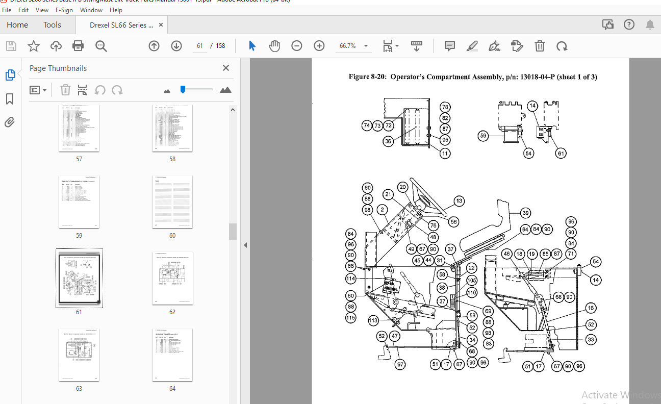
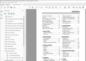
TABLE OF CONTENTS:
Drexel SL66 Series Base IPB SwingMast Lift Truck Parts Manual 13001-13 – PDF DOWNLOAD
Illustrated Parts Breakdown (IPB)General Information
- General: Page 8-5
- Abbreviations: Page 8-5
- Phantoms / Reference Parts: Page 8-5
- Task Groups/Assemblies: Page 8-5
Top Assembly
- Top Assembly Group, p/n: 13401: Page 8-7 to 8-10
- Figures 8-1 to 8-4: Pages 8-11 to 8-14
Traction and Drive Assemblies
- Traction Drive Assembly, p/n: 8856-02-K: Page 8-16
- Figure 8-5: Page 8-17
- Traction Motor, p/n: 50298-C: Page 8-18
- Figure 8-6: Page 8-19
- Brake Assembly Modification, p/n: 1406982-B: Page 8-20
- Figure 8-7: Page 8-21
- Drive Axle, p/n: 52994-D: Pages 8-22 to 8-24
- Figure 8-8: Page 8-25
- Differential Assembly, p/n: 20230-A: Page 8-26
- Figure 8-9: Page 8-27
- Brake Assembly, p/n: 53002-E: Page 8-28
- Figure 8-10: Page 8-29
Steering Assemblies
- Steer Axle Assembly, p/n: 13113-06-C: Pages 8-31 to 8-32
- Figure 8-11: Page 8-33
- Wheel Brake Assembly, Left Hand, p/n: 13597-A: Page 8-35
- Wheel Brake Assembly, Right Hand, p/n: 13596-A: Page 8-36
- Figure 8-12: Page 8-37
- Brake Assembly, 10.5 x 2.5, p/n: 18062-D: Page 8-38
- Figure 8-13: Page 8-39
- Steer Cylinder Assembly, p/n: 11171-A: Page 8-40
- Figures 8-14 to 8-15: Pages 8-41 to 8-43
- Tie Rod Assembly, p/n: 11158: Page 8-44
- Figure 8-16: Page 8-45
Pump and Motor Assemblies
- Pump and Motor Assembly, p/n: 9978-8: Page 8-48
- Figure 8-17: Page 8-49
- Electric Motor, Pump, p/n: 9617-D: Page 8-50
- Figure 8-18: Page 8-51
- Double Vane Pump, p/n: 21197-D: Page 8-52
- Figure 8-19: Page 8-53
Operator’s Compartment
- Operator’s Compartment, p/n: 13018-04-P: Pages 8-55 to 8-57
- Figures 8-20 to 8-22: Pages 8-59 to 8-61
Accelerator Assemblies
- Accelerator Assembly, p/n: 13522-C: Page 8-62
- Figure 8-23: Page 8-63
- Accelerator Switch Assembly, p/n: 13523-C: Page 8-64
- Figure 8-24: Page 8-65
Reservoir and Pump Assemblies
- Reservoir Assembly, p/n: 11750-01-8: Page 8-66
- Figure 8-25: Page 8-67
- Pump and Motor Assembly, p/n: 50454-A: Page 8-68
- Figure 8-26: Page 8-68
- Steering Pump, p/n: 50654-A: Page 8-69
- Figure 8-27: Page 8-69
- Motor, Steering Pump, p/n: 50656-A: Page 8-70
- Figure 8-28: Page 8-71
Steering Wheel and Control Panels
- Steering Wheel and Horn Assembly, p/n: 1410602-A: Page 8-72
- Figure 8-29: Page 8-73
- Dash Panel Assembly, p/n: 1402690-C: Page 8-74
- Figure 8-30: Page 8-74
- Operator’s Control Panel Assembly, p/n: 1402667-G: Page 8-76
- Figure 8-31: Page 8-77
- Panel Assembly, Key Switch, p/n: 16212: Page 8-78
- Figure 8-32: Page 8-78
Knobs and Valves
- Knobs: Pivot, Shift, Lift & Tilt, p/n: 50382-03, -01, -04, -02: Page 8-80
- Figure 8-33: Page 8-81
- Control Valve, p/n: 22065-8: Page 8-82
- Figure 8-34: Page 8-83
- Control Valve, 3-way, p/n: 23737-C: Page 8-84
- Figure 8-35: Page 8-85
Steering Control Units
- Steering Control Unit, p/n: 25763-C: Page 8-86
- Figure 8-36: Page 8-87
- Intermediate Panel Assembly, p/n: 1402716-C: Page 8-88
- Figure 8-37: Page 8-89
- Pump Switch Resistor Assembly, p/n: 37887: Page 8-90
- Figure 8-38: Page 8-90
Steering Columns and Battery Connectors
- Steer Column, p/n: 25040-C: Page 8-91
- Figure 8-39: Page 8-91
- Battery Connector, Gray SB-350, p/n: 25165-A: Page 8-92
- Figure 8-40: Page 8-93
Shift Switch and Driver’s Seat
- Shift Switch Interlock Installation, p/n: 13633-B: Page 8-94
- Figure 8-41: Page 8-95
- Driver’s Seat, p/n: 1413607-A: Page 8-96
- Figure 8-42: Page 8-97
Side Shift Assembly
- Side Shift Assembly, p/n: 10273-J: Pages 8-99 to 8-100
- Figures 8-43 to 8-45: Pages 8-101 to 8-103
Shift Cylinder and Pivot Assemblies
- Shift Cylinder Breakdown, p/n: 6790-B: Page 8-104
- Figure 8-46: Page 8-105
- Pivot Arm Machined, p/n: 9775 – C: Page 8-108
- Pivot Shaft Assembly, p/n: 10133-B: Page 8-110
- Figure 8-47: Page 8-111
Brake Systems
- Service Brake System, p/n: 1413804-B: Pages 8-113 to 8-114
- Figures 8-48 to 8-49: Pages 8-115 to 8-117
- Master Cylinder, 150 PSI Relief, p/n: 1413595-A: Page 8-118
Hydraulic Parts
- Hydraulic Parts Group, p/n: 10550-Y: Pages 8-119 to 8-121
- Figures 8-50 to 8-53: Pages 8-122 to 8-125
Umbilical and Solenoid Assemblies
- Umbilical Assembly, p/n: 10692-A: Page 8-126
- Figure 8-54: Page 8-127
- Solenoid Valve, SAE 6, p/n: 51199-B: Page 8-128
- Figure 8-55: Page 8-129
- Solenoid Valve, SAE-12, p/n: 51209-8: Page 8-130
- Figure 8-56: Page 8-131
Electrical Panels
- Electrical Panel Assembly, p/n: 16075-R: Pages 8-133 to 8-134
- Figure 8-57: Page 8-135
- Mounting Panel Assembly, p/n: 16076-D: Page 8-136
- Figure 8-58: Page 8-137
- SCR Panel – EV-1C, p/n: 50741-8: Page 8-138
- Figure 8-59: Page 8-139
Contactors
- Contactor, DPDT, 300A, 36VDC, p/n: 28888-D: Page 8-140
- Figure 8-60: Page 8-141
- Contactor, SPNO, 300A, 36VDC, p/n: 28889-0: Page
More products