$36
Drexel SL66 Series Base IPB SwingMast Lift Truck Parts Manual 16027-19 – PDF DOWNLOAD
Drexel SL66 Series Base IPB SwingMast Lift Truck Parts Manual 16027-19 – PDF DOWNLOAD
FILE DETAILS:
Drexel SL66 Series Base IPB SwingMast Lift Truck Parts Manual 16027-19 – PDF DOWNLOAD
Language : English
Pages : 210
Downloadable : YesFile Type : PDF
IMAGES PREVIEW OF THE MANUAL:
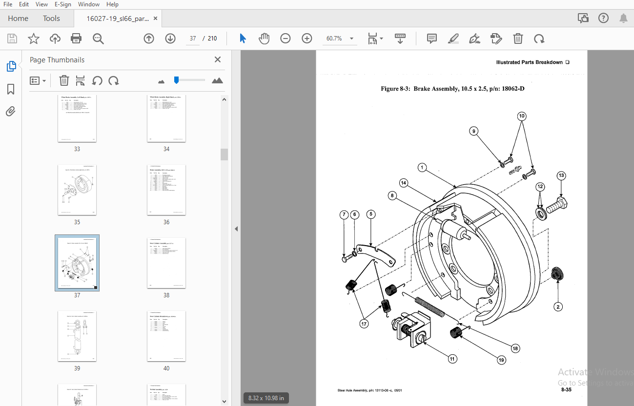

TABLE OF CONTENTS:
Drexel SL66 Series Base IPB SwingMast Lift Truck Parts Manual 16027-19 – PDF DOWNLOAD
General 8-7
Abbreviations 8-7
Phantoms/ Reference Parts 8-7
Task Groups/Assemblies 8-7
Final Assembly, 48 Volt, p/n: 16027-19-B 8-9
Drive Assembly, Traction, p/n: 8856-01-L 8-12
Figure 8-1: Drive Assembly, Traction, p/n: 8856-01-L 8-13
Traction Motor, p/n: 50298-C 8-14
Figure 8-2: Traction Motor, p/n: 50298-B 8-15
Brake Assembly Modification, p/n: 1406982-B 8-16
Figure 8-3: Brake Assembly Modification, p/n: 1406982-B 8-17
Drive Axle Assembly, p/n: 52993-C 8-18
Drive Axle Assembly, p/n: 52993-C (continued) 8-19
Drive Axle Assembly, p/n: 52993-C (continued) 8-20
Figure 8-4: Drive Axle Assembly, p/n: 52993-C 8-21
Differential, p/n: 20230-A 8-22
Figure 8-5: Differential, p/n: 20230-A 8-23
Brake Assembly, p/n: 53002-E 8-24
Figure 8-6: Brake Assembly, p/n: 53002-E 8-25
Steer Axle Assembly, p/n: 13113-06-C 8-27
Steer Axle Assembly, p/n: 13113-06-C (continued) 8-28
Figure 8-1: Steer Axle Assembly, p/n: 13113-06-C 8-29
Wheel Brake Assembly, Left Hand, p/n: 13597-A 8-31
Wheel Brake Assembly, Right Hand, p/n: 13596-A 8-32
Figure 8-2: Wheel Brake Assembly, Right Hand, p/n: 13596-A 8-33
Brake Assembly, 10 5 x 2 5, p/n: 18062-D 8-34
Figure 8-3: Brake Assembly, 10 5 x 2 5, p/n: 18062-D 8-35
Steer Cylinder Assembly, p/n: 11171-A 8-36
Figure 8-4: Steer Cylinder Assembly, p/n: 1416946-A 8-37
Steer Cylinder Breakdown, p/n: 1416946-A 8-38
Figure 8-5: Steer Cylinder Breakdown, p/n: 1416946-A 8-39
Tie Rod Assembly, p/n: 11158 8-40
Figure 8-6: Tie Rod Assembly, p/n: 11158 8-41
Service Brake System, p/n: 1413803-C 8-43
Service Brake System, p/n: 1413803-C (continued) 8-44
Figure 8-1: Service Brake System, p/n: 1413803-C (sheet 1 of 2) 8-45
Figure 8-2: Service Brake System, p/n: 1413803-C (sheet 2 of 2) 8-46
·sL66″ Serles, 48 V, Base unlt, p/n: 16027 -19-b, 05/01 8-1
Master Cylinder, 150 PSI, p/n: 1413595-A 8-47
Pump and Motor Assembly, p/n: 9978-02-A 8-50
Figure 8-1: Pump a nd Motor Assembly, p/n: 9978-02-A , 8-51
Pump, Motor, p/n: 9617-D 8-52
Figure 8-2: Pump, Motor, p/n: 9617-D 8-53
Double Pump, 8 x 3 Gpm, p/n: 51483-02-A : 8-54
Figure 8-3: Double Pump, 8 x 3 Gpm, p/n: 51483-02-A 8-55
Hydraulic System, 48v, p/n: 10550-03-N 8-58
Hydraulic System, 48v, p/n: 10550-03-N (continued) 8-59
Hydraulic System, 48v, p/n: 10550-03-N (continued) 8-60
Figure 8-1: Hydraulic System, 48v, p/n: 10550-03-N (sheet 1 of4) 8-61
Figure 8-2: Hydraulic System, 48v, p/n: 10550-03-N (sheet 2 cif 4) 8-62
Figure 8-3: Hydraulic System, 48v, p/n: 10550-03-N (sheet 3 of 4) 8-63
Figure 8-4: Hydraulic System, 48v, p/n: 10550-03-N (sheet 4 of 4) 8-65
Umbilical Assembly, p/n: 10692-A ,: 8-66
Figure 8-5: Umbilical Assembly, p/n: 10692-A 8-67
Electrical Panel Assembly, p/n: 16075-01-R 8-69
Electrical Panel Assembly, p/n: 16075-01-R (continued) 8-70
Figure 8-1: Electrical Panel Assembly, p/n: 16075-01-R 8-71
Mounting Panel Assembly, p/n: 16076-D , , 8-72
Figure 8-2: Mounting Panel Assembly, p/n: 16076-D 8-73
SCR Controller Panel Ev-1c, p/n: 50741-B 8-74
Figure 8-3: SCR Controller Panel Ev-1c, p/n: 50741-B 8-75
Contactor, 300a, DPDT, 48v, p/n: 28888°50-B 8-76
Figure 8-4: Contactor, 300a, DPDT, 48v, p/n: 28888-50-B 8-77
Contactor, 300a, SPNO, 48v, p/n: 28889-50-B : 8-78
Figure 8-5: Contactor, 300a, SPNO, 48v, p/n: 28889-50-B 8-79
Contactor, 300A, SPNO, 48V, p/n: 1413594-A 8-80
Figure 4-6: Contactor, 300A, SPNO, 36V, p/n: 1413594-A 8-81
Wire Assembly, Curtis Bdi, p/n: 1413485-A 8-83
Power Cable Harness, p/n: 16203-D 8-86
Figure 8-1: Power Cable Harness, p/n: 16203-D 8-87
Travel Speed Switch, p/n: 16019-02 : 8-90
Figure 8-1: Travel Speed Switch, p/n: 16019-02 8-91
Load Sensing Valve Assembly, p/n: 9988-01-E 8-94
Figure 8-1: Load Sensing Valve Assembly, p/n: 9988-01-E 8-95
Operator Cab Assembly, p/n: 13018-10-B 8-97
Operator Cab Assembly, p/n: 13018-10-B (continued) 8-98
Operator Cab Assembly, pin: 13018-10-8 (continued) , 8-99
Figure 8-1: Operator Cab Assembly, p/n: 13018-10-8 (sheet 1 of 3) : 8-100 ·
Figure 8-2: Operator Cab Assembly, p/n: 13018-10-8 (sheet 2 of 3) 8-101
Figure 8-3: Operator Cab Assembly, p/n: 13018-10-8 (sheet 3 of 3) 8-103
Raised Operator Cab, p/n: 16028-8 8-104
Raised Operator Cab, p/n: 16028-8 (continued) 8-105
Accelerator Assembly, p/n: 13522-C 8-106
Figure 8-4: Accelerator Assembly, p/n: 13522-C 8-107
Accelerator Switch Assembly, p/n: 13523-C 8-108
Figure 8-5: Accelerator Switch Assembly, p/n: 13523-C 8-109
Reservoir Assembly, p/n: 11750-01-8 8-110
Figure 8-6: Reservoir Assembly, p/n: 11750-01-8 8-111
Steer Pump and Motor Assembly, p/n: 50454-01-8 8-112
Figure 8-7: Steer Pump and Motor Assembly, p/n: 50454-01-8 8-113
Power Steering Pump, p/n: 50654-A 8-114
Figure 8-8: Power Steering Pump, p/n: 50654-A 8-115
Power Steer Motor, p/n: 50656-02-A 8-116
Figure 8-9: Power Steer Motor, p/n: 50656-02-A 8-117
Steering Wheel and Horn, p/n: 1410602-A 8-118
Figure 8-10: Steering Wheel and Horn, p/n: 1410602-A 8-119
Dash Panel Assembly, p/n: 1419200-A 8-120
Figure 8-11: Dash Panel Assembly, p/n: 1419200-A 8-121
Operator Control Panel, p/n: 1419201-C 8-122
Figure 8-12: Operator Control Panel, p/n: 1419201-A 8-123
Key Switch Assembly, p/n: 16212 8-124
Figure 8-13: Key Switch Assembly, p/n: 16212 8-125
Pivot Knob, p/n: 50382-03 8-126
Lift Knob, p/n: 50382-01 8-126
Shift Knob, p/n: 50382-04 8-126
Tilt Knob, p/n: 50382-02 8-126
Figure 8-14: Knobs – Pivot, Lift, Shift & Tilt, p/n: 50382-03, -01, 04, -02 8-127
Control Valve, p/n: 22065-8 8-128
Figure 8-15: Control Valve, p/n: 22065-8 8-129
Control Valve, 1-Spool, p/n: 23737-8 8-130
Figure 8-16: Control Valve, 1-Spool, p/n: 23737-8 8-131
Intermediate Panel Assembly, p/n: 1402727-8 8-132
Figure 8-17: Intermediate Panel Assembly, p/n: 1402727-8 8-133
Steering Column, p/n: 25040-C 8-134
Figure 8-18: Steering Column, p/n: 25040-C 8-135
Steering Control Unit, p/n: 25763-C 8-136
Figure 8-19: Steering Control Unit, p/n: 25763-C 8-137
Driver’s Seat, Gs12, p/n: 1414461-A 8-139
Figure 8-20: Driver’s Seat, Gs12, p/n: 1414461-A 8-139
Seat Service Breakdown, p/n: 1410317-E 8-140
Figure 8-21: Seat Assembly, Cloth, p/n: 1410317-E 8-141
Battery Connector, Gray, 36 Volt, p/n: 25165-A , 8-142
Figure 8-22: Battery Connector, Gray, 36 Volt, p/n: 25165-A 8-143
Shift Switch Interlock Installation, p/n: 13633-8 8-144
Figure 8-23: Shift Switch Interlock Installation, p/n: 13633-8 8-145
Seat Be It Modification, p/n: 1419187-A 8-148
Figure 8-1: Seat Belt Modification, p/n: 1419187-A , 8-149
Battery Slider, p/n: 1419179-A , 8-152
Figure8-1: Battery Slider, p/n: 1419179-A 8-153
Overhead Guard Weldment, p/n: 13016-06-C 8-155
Pivot Shaft Assembly, p/n: 10133-8 8-158
Figure 8-1: Pivot Shaft Assembly, p/n: 10133-8 8-159
Side Shift Assembly, p/n: 10273-01-A 8-161
Side Shift Assembly, p/n: 10273-01-A (continued) 8-162
Figure 8-1: Side Shift Assembly, p/n: 10273-01 °A (sheet 1 of 3) 8-163
Figure 8-2: Side Shift Assembly, p/n: 10273-01-A (sheet 2 of 3) 8-164
Figure 8-3: Side Shift Assembly, p/n: 10273-01-A (sheet 3 of 3) 8-165
Shift Cylinder, p/n: 6790-B 8-166
Figure 8-4: Shift Cylinder, p/n: 6790-8 , 8-167
Shift Cylinder, Modified, p/n: 1419206-A , 8-168
Interlock Switches Modification , p/n: 1419314-A : 8-170
Figure 8-1: Interlock Switches Modification, p/n: 1419314-A 8-171 ·
Top Assembly Group, 48v, p/n: 13401-08-A 8-173
Top Assembly Group, 48v, p/n: 13401-08-A (continued) 8-174
Top Assembly Group, 48v, p/n: 13401-08-A (continued) 8-175
Top Assembly Group, 48v, p/n: 13401-08-A (continued) 8-176
Figure 8-1: Top Assembly Group, 48 Vdc, p/n: 13401-08-a (sheet 1 of 4) 8-177
Figure 8-2: Top Assembly Group, 48 Vdc, p/n: 13401-08-a (s heet 2 of 4) , 8-178
Figure 8-3: Top Assembly Group, 48 Vdc, p/n: 13401 c08-a (sheet 3 of 4) 8-179
Figure 8-4: Top Assembly Group, 48 Vdc, p/n: 13401-08-a (sheet 4 of 4) 8-181
Pivot Cylinder, p/n: 6914-F , 8-182
Figure 8-5: Pivot Cylinder, p/n: 6914-F , : 8-183
Cylinder Tilt Modification, p/n: 9822-06-A 8-185
Figure 8-6: Cylinder Tilt Modification, p/n: 9822-06-A 8-185
Tilt Cylinder Assembly, p/n: 6982-K 8-186
Figure 8-7: Tilt Cylinder, p/n: 6982-K 8-187
Pivot Switch Assembly, p/n: 12360-A 8-188
Figure 8-8: Pivot Switch Assembly, p/n: 12360-A 8-189
Counter Balance Assembly, p/n: 10607-B 8-190
Figure 8-9: Counter Balance Assembly, p/n: 10607-B 8-191
Tilt Indicator Kit, p/n: 11520-A 8-192
Figure 8-10: Tilt Indicator Kit, p/n: 11520-A 8-193
Tail Lamp Installation, p/n: 9280-01-A 8-194
Figure 8-11: Tail Lamp Installation, p/n: 9280-01-A 8-195
Light, Stop and Tail, 48 Vdc, p/n: 25055-2-B 8-196
Figure 8-12: Light, Stop and Tail, 48 Vdc, p/n: 25055-2-B 8-197
Horn Assembly, p/n: 1415796-A 8-198
Figure 8-13: Horn Assembly, p/n: 1415796-A 8-199
Fan Assembly, SCR Cooling, p/n: 1411316-A 8-200
Figure 8-14: Fan Assembly, SCR Cooling, p/n: 1411316-A 8-201
Schematics and Diagrams 8-202
Hour Meter, with Vibration, p/n: 1414385-A 8-204
Figure 8-1: Hour Meter, with Vibration, p/n: 1414385-A 8-205
Enamel Paint, Yellow, p/n: 37260-04-A 8-207
More products