Starting from:
$38
DREXEL SL66 Series Base Unit IPB SwingMast Lift Truck Parts Manual 13001-06 – PDF DOWNLOAD
DREXEL SL66 Series Base Unit IPB SwingMast Lift Truck Parts Manual 13001-06 – PDF DOWNLOAD
FILE DETAILS:
DREXEL SL66 Series Base Unit IPB SwingMast Lift Truck Parts Manual 13001-06 – PDF DOWNLOAD
Language : English
Pages : 176
Downloadable : Yes
File Type : PDF
IMAGES PREVIEW OF THE MANUAL:
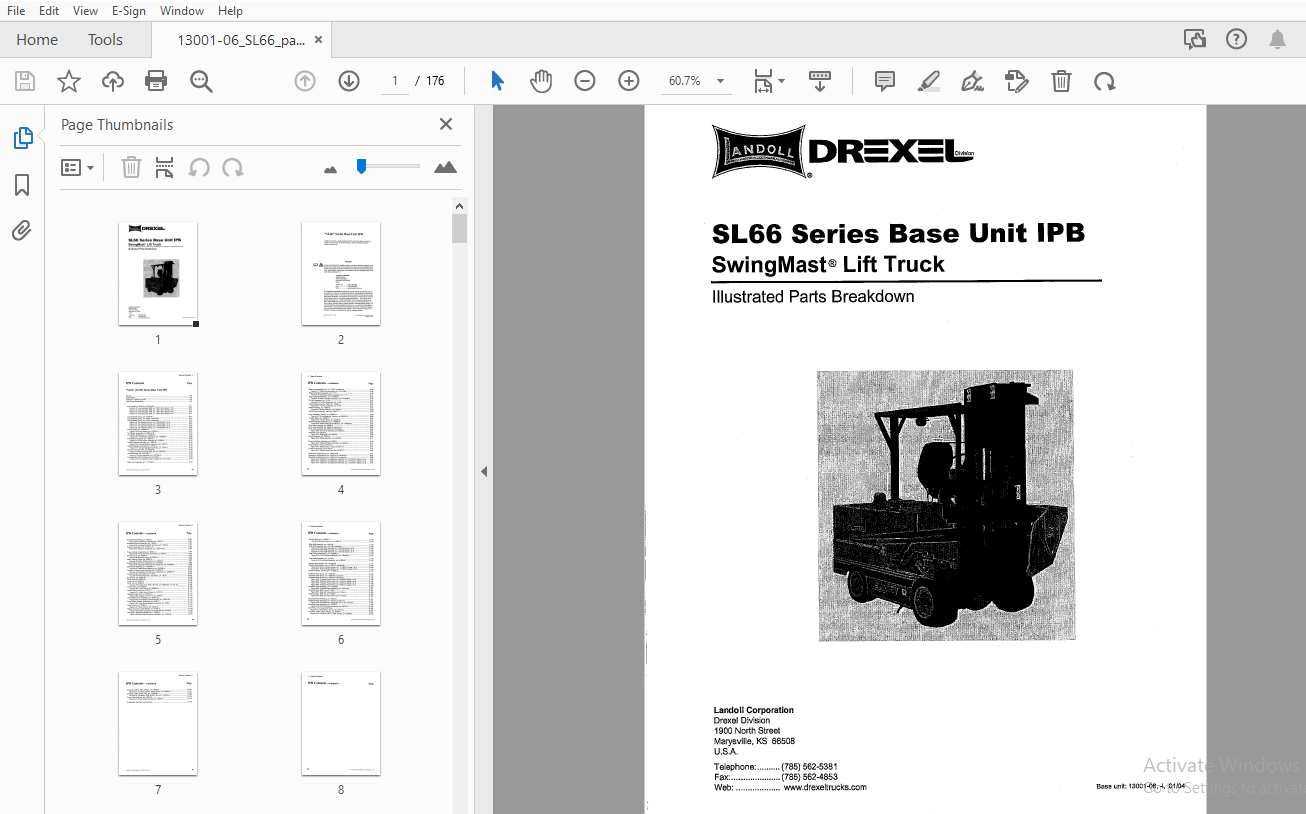
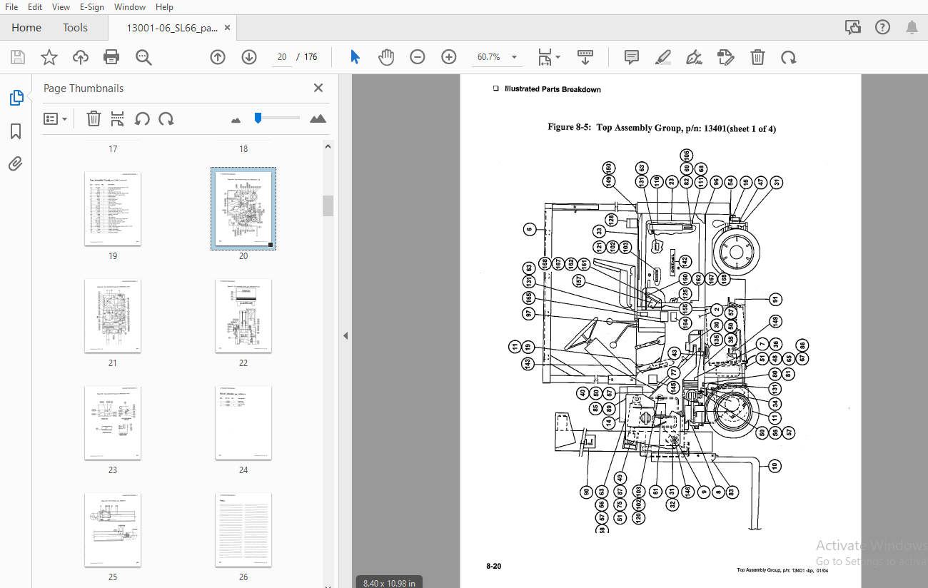
TABLE OF CONTENTS:
DREXEL SL66 Series Base Unit IPB SwingMast Lift Truck Parts Manual 13001-06 – PDF DOWNLOAD
General
- General Information 8-9
- Abbreviations 8-9
- Phantoms / Reference Parts 8-9
- Task Groups/Assemblies 8-9
Final Assembly
- Final Assembly, SL66, p/n: 13001-06-J 8-11
- Figure 8-1: Final Assembly, SL66, p/n: 13001-06-J (Sheet 1 of 4) 8-12
- Figure 8-2: Final Assembly, SL66, p/n: 13001-06-J (Sheet 2 of 4) 8-13
- Figure 8-3: Final Assembly, SL66, p/n: 13001-06-J (Sheet 3 of 4) 8-14
- Figure 8-4: Final Assembly, SL66, p/n: 13001-06-J (Sheet 4 of 4) 8-15
Top Assembly Group
- Top Assembly Group, p/n: 13401-BP 8-17
- Top Assembly Group, p/n: 13401 (continued) 8-18
- Top Assembly Group, p/n: 13401 (continued) 8-19
- Figure 8-5: Top Assembly Group, p/n: 13401 (Sheet 1 of 4) 8-20
- Figure 8-6: Top Assembly Group, p/n: 13401 (Sheet 2 of 4) 8-21
- Figure 8-7: Top Assembly Group, p/n: 13401 (Sheet 3 of 4) 8-22
- Figure 8-8: Top Assembly Group, p/n: 13401 (Sheet 4 of 4) 8-23
Pivot Cylinder
- Pivot Cylinder, p/n: 1422814-A 8-24
- Figure 8-9: Pivot Cylinder, p/n: 1422814-A 8-25
Tilt Cylinder Assembly
- Tilt Cylinder Assembly, p/n: 9822-01-B 8-27
- Tilt Cylinder Breakdown, p/n: 1422853-A 8-28
- Figure 8-10: Tilt Cylinder Breakdown, p/n: 1422853-A 8-29
Pivot Switch Assembly
- Pivot Switch Assembly, p/n: 12360-A 8-30
- Figure 8-11: Pivot Switch Assembly, p/n: 12360-A 8-31
Counter Balance Assembly
- Counter Balance Assembly, p/n: 10607-B 8-32
- Figure 8-12: Counter Balance Assembly, p/n: 10607-B 8-33
Tail and Stoplight Assembly
- Tail and Stoplight Assembly, p/n: 13707-C 8-34
- Figure 8-13: Tail and Stoplight Assembly, p/n: 13707-C 8-35
- Stop and Tail Light, 36V, p/n: 25055-B 8-36
- Figure 8-14: Stop and Tail Light, 36V, p/n: 25055-B 8-37
Horn Assembly
- Horn Assembly, p/n: 1415796-A 8-38
- Figure 8-15: Horn Assembly, p/n: 1415796-A 8-39
Fan Assembly, SCR Cooling
- Fan Assembly, SCR Cooling, p/n: 1411316-A 8-40
- Figure 8-16: Fan Assembly, SCR Cooling, p/n: 1411316-A 8-41
Steer Axle Assembly
- Steer Axle Assembly, p/n: 13113-06-C 8-43
- Steer Axle Assembly, p/n: 13113-06-C (continued) 8-44
- Figure 8-17: Steer Axle Assembly, p/n: 13113-06-C 8-45
Steering Cylinder Assembly
- Steering Cylinder Assembly, p/n: 11171 8-46
- Figure 8-18: Steering Cylinder Assembly, p/n: 11171 8-47
- Steer Cylinder Breakdown, p/n: 1416946-A 8-48
- Figure 8-19: Steer Cylinder Breakdown, p/n: 1416946-A 8-49
Tie Rod Assembly
- Tie Rod Assembly, p/n: 11158 8-50
- Figure 8-20: Tie Rod Assembly, p/n: 11158 8-51
Wheel Brake Assembly
- Wheel Brake Assembly, Right, p/n: 13596-A 8-52
- Figure 8-21: Tie Rod Assembly, p/n: 11158 8-53
- Brake Assembly, p/n: 18062-D 8-54
- Figure 8-22: Brake Assembly, p/n: 18062-D 8-55
- Wheel Brake Assembly, Left, p/n: 13597-A 8-56
Drive Assembly, Traction
- Drive Assembly, Traction, p/n: 8856-01-L 8-58
- Figure 8-23: Drive Assembly, Traction, p/n: 8856-01-L 8-59
Traction Motor
- Traction Motor, p/n: 50298-C 8-60
- Figure 8-24: Traction Motor, p/n: 50298-8 8-61
Brake Assembly Modification
- Brake Assembly Modification, p/n: 1406982-8 8-62
- Figure 8-25: Brake Assembly Modification, p/n: 1406982-8 8-63
Drive Axle Assembly
- Drive Axle Assembly, p/n: 52993-C 8-64
- Drive Axle Assembly, p/n: 52993-C (continued) 8-65
- Drive Axle Assembly, p/n: 52993-C (continued) 8-66
- Figure 8-26: Drive Axle Assembly, p/n: 52993-C 8-67
Differential
- Differential, p/n: 20230-A 8-68
- Figure 8-27: Differential, p/n: 20230-A 8-69
Brake Assembly
- Brake Assembly, p/n: 53002-E 8-70
- Figure 8-28: Brake Assembly, p/n: 53002-E 8-71
Pump and Motor Assembly
- Pump and Motor Assembly, p/n: 9978-B 8-74
- Figure 8-29: Pump and Motor Assembly, p/n: 9978-8 8-75
- Electric Motor, Pump, p/n: 9617-D 8-76
- Figure 8-30: Electric Motor, Pump, p/n: 9617-D 8-77
Double Vane Pump
- Double Vane Pump, p/n: 21197-D 8-78
- Figure 8-31: Double Vane Pump, p/n: 21197-D 8-79
Operator’s Compartment
- Operator’s Compartment, p/n: 13018-04-P 8-81
- Operator’s Compartment, p/n: 13018-04-P (continued) 8-82
- Operator’s Compartment, p/n: 13018-04-P (continued) 8-83
- Figure 8-32: Operator’s Compartment Assembly, p/n: 13018-04-P (Sheet 1 of 3) 8-85
- Figure 8-33: Operator’s Compartment Assembly, p/n: 13018-04-P (Sheet 2 of 3) 8-86
- Figure 8-34: Operator’s Compartment Assembly, p/n: 13018-04-P (Sheet 3 of 3) 8-87
Accelerator Assembly
- Accelerator Assembly, p/n: 13522-C 8-88
- Figure 8-35: Accelerator Assembly, p/n: 13522-C 8-89
Accelerator Switch Assembly
- Accelerator Switch Assembly, p/n: 13523-C 8-90
- Figure 8-36: Accelerator Switch Assembly, p/n: 13523-C 8-91
Reservoir Assembly
- Reservoir Assembly, p/n: 11750-01-B 8-92
- Figure 8-37: Reservoir Assembly, p/n: 11750-01-B 8-93
Pump and Motor Assembly
- Pump and Motor Assembly, p/n: 50454-A 8-94
- Figure 8-38: Pump and Motor Assembly, p/n: 50454-A 8-94
Steering Pump
- Steering Pump, p/n: 50654-A 8-95
- Figure 8-39: Steering Pump, p/n: 50654-A 8-95
Motor, Steering Pump
- Motor, Steering Pump, p/n: 50656-A 8-96
- Figure 8-40: Motor, Steering Pump, p/n: 50656-A 8-97
Steering Wheel and Horn Assembly
- Steering Wheel and Horn Assembly, p/n: 1410602
More products