$40
DREXEL SL66, SL77 & SL88 SERIES SERVICE & PARTS MAINTENANCE MANUAL 1421635 – PDF DOWNLOAD
DREXEL SL66, SL77 & SL88 SERIES SERVICE & PARTS MAINTENANCE MANUAL 1421635 – PDF DOWNLOAD
FILE DETAILS:
Language : English
Pages : 428
Downloadable : YesFile Type : PDF
IMAGES PREVIEW OF THE MANUAL:
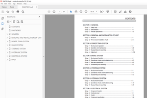
TABLE OF CONTENTS:
DREXEL SL66, SL77 & SL88 SERIES SERVICE & PARTS MAINTENANCE MANUAL 1421635 – PDF DOWNLOAD
8.1 Site Supervision
8.2 Operator Seat BeltFigure 1: Belt Release ButtonSeat Safety Switches and Battery Latch
Parking Brake8.3 Tipping Hazards
Longitudinal tipping can occur when:
Lateral tipping can occur when:8.4 Traveling and Load Handling
8.5 Load Handling
Front Load Traveling
Side Load Traveling – Long Loads8.6 Speed
8.7 Visibility
8.8 Battery Care
Battery Compartment Interlock OptionsFigure 2: Optional Battery Retainer Safety Gate & Interlocks8.9 Service Repair
8.10 Safety Labels
8.11 Available Options
Fork Positioner, Non-Side ShiftingFigure 3: Fork Check PointsFire Extinguisher
In Case of a Fire
Overload Sensing Option
Lift Limit Interlock OptionFigure 4: Lift Limit InterlockTruck Overview
1.1 Introduction
1.1.1 Description
1.1.2 Functional Description
Frame
Propellant
Drive Train
Electrical System
Safety Interlock
Battery
SCR Controller
Solenoid Contactors
Safety Interlocks
Meters
Hydraulic Sub-System
Pivot and Shift System
MastFigure 1-1: Mast in Collapsed Position
Figure 1-2: Mast in Free Lift
Figure 1-3: Mast in Extended Position
Figure 1-4: Quadplex Mast in Collapsed Position1.2 Operating Controls
Figure 1-5: Driver’s Controls1.3 Truck Specifications
SL66 Series Reach Lift Trucks
SL77 Series Reach Lift Trucks
SL88 Series Reach Lift Trucks1.4 Models
1.4.1 EE Series (Electrical Enclosure)
1.4.2 Hi-Low Series (Optional)General
Figure 1-8: Thermal Switches
Figure 1-7: Air Filter
Figure 1-8: Heat Exchanger
Figure 1-9: Closed-Loop Mode
Figure 1-10: Open-Loop Mode
Figure 1-11: Console Intake
Figure 1-12: Electrical Compartment Vent1.5 Options
1.5.1 Auto-Guidance System
Figure 1-13: Automatic Guidance System Overview
1.5.2 Fire Extinguisher
1.5.3 Fork Positioner
Figure 1-14: Fork Positioner Overview/Setting
1.5.4 Lift Limit Interlock Option
Figure 1-15: Lift Limit Interlock
1.5.5 Lights and Alarms
Figure 1-16: Lights and Alarm
1.5.6 Overload Sensing Option
1.5.7 Proximity Sensor Option
Figure 1-17: Proximity Sensor
1.5.8 Rear View Mirror
1.5.9 Turn and Hazard Signals
Figure 1-18: Turn/Hazard ModuleReceiving and Inspection
2.1 Receiving Your Truck
2.1.1 Items Furnished with Your Truck
2.1.2 Items Required
2.1.3 Tools and Test Equipment
2.2 To Prepare the Truck
2.2.1 Charging a Wet Battery
Using the HydrometerFigure 2-1: Battery Charge State Using a Hydrometer
Table 2-1: Specific Gravity Corrections for Electrolyte Temperature2.2.2 Charging a Dry Battery
2.3 Inspection Checklist
2.3.1 Visual Checks
2.3.2 Routine ChecksFigure 2-2: Battery Retainer Safety Gate and Bar (Optional)
Figure 2-3: Seat Battery Retainer Latch
Figure 2-4: Lift Limit Interlock Option2.4 Replacing the Battery
2.4.1 To Replace a BatteryFigure 2-5: Removing the Battery
Figure 2-6: Checking Steer Axle and Articulating Blocks2.5 Storage, Towing, or Shipping
2.5.1 Truck Storage
2.5.2 Battery Storage
2.5.3 Towing the Truck (Optional)Figure 2-7: Optional Tie-Down/Lift Post Used for Towing
2.5.4 To Ship the TruckBasic Operation
3.1 To Begin Operating
3.1.1 Pre-Operation Checklist
3.1.2 Adjusting the Driver’s SeatFigure 3-1: Sample: Driver’s Seat Controls
Figure 3-2: Weight Adjustment (Optional)Seat Belt
Figure 3-3: Driver’s Seat Belt3.1.3 Tilt Steering Panel (Optional)
Figure 3-4: Tilt Steering Adjust (Optional)3.1.4 Fork Adjustment
Manual Fork AdjustFigure 3-5: Unlocking the Forks
Fork Positioner Option – Automatic3.2 Driving the Truck
3.2.1 Practice Session3.3 The Mast
3.3.1 Practice SessionFigure 3-6: Lift Lever Icon
Figure 3-7: Tilt Lever Icon
Figure 3-8: Fork Level Gauge
Figure 3-9: Pivot Lever Icon
Figure 3-10: Shift Lever Icon3.4 Handling Normal Loads
3.4.1 To Pick Up the LoadFigure 3-11: Sample – Aligning the Truck to the Pallet Opening
Figure 3-12: Sample – Pivoting the Forks 45°
Figure 3-13: Sample – Shifting the Forks into the Pallet
Figure 3-14: Tilting the Load
Figure 3-15: Sample – Pivoting the Load 45°3.4 Handling Normal Loads – Continued
3.4.2 To Deliver a LoadFigure 3-16: Tilting the Load
Figure 3-17: Sample – Aligning the Load to the Rack
Figure 3-18: Sample – Pivoting the Load 45°
Figure 3-19: Sample – Placing the Load into the Rack
Figure 3-20: Leveling the Load
Figure 3-21: Sample – Normal Driving Position3.5 Side Loading (Long Loads)
3.5.1 To Pick Up a Long LoadFigure 3-22: Sample – Aligning the Truck to the Long Load Pallet
Figure 3-23: Sample – Shifting the Forks into the Pallet
Figure 3-24: Sample – Removing the Load
Figure 3-25: Sample – Traveling with a Long Load3.5.2 To Deliver a Long LoadFigure 3-26: Sample – Aligning the Load to the Rack
Figure 3-27: Sample – Rotating the Long Load into the Rack
Figure 3-28: Sample – Shifting the Load into the RackFor More Experienced Drivers…Figure 3-29: Sample – Backing the Load into the Slot
Figure 3-30: Pivoting the Load into the SlotAvailable Options
3.6 Auto-Guidance Option
3.6.1 Approaching the Aisle
3.7 Fire Extinguisher OptionPreventive maintenance
4 1 tables
4 1 1 Preventive maintenance schedule 4-9
Table 1: Preventive maintenance schedule 4-9
4 1 2 Recommended lubricants 4-12
Table 2: Recommended lubricants 4-12
4 1 3 Torque values, English 4-13
Table 3: English torque specifications 4-13
4 1 4 Torque values, Metric 4-14
Table 4: Metric torque specifications 4-14
4 2 overview
4 2 1 Tools or equipment required 4-16
Special tools required 4-17
Safety equipment required 4-17
4 3 daily inspection
4 3 1 Check batteries 4-17
To check the battery: 4-18
Figure 4-1: Battery charge state using a hydrometer 4-18
4 3 2 Check power steering 4-19
Figure 4-2: Check power steering 4-19
4 3 3 Check control lever reaction 4-20
Figure 4-3: Control levers Uoystick) 4-20
4 3 4 Check the return-to-neutral 4-20
4 3 5 Check primary lift chain 4-21
Figure 4-4: Fork heel to floor adjust 4-21
4 3 6 Inspect tires 4-22
Figure 4-5: Tire tread inspection 4-22
Chunking (chipping) or embedded objects 4-23
Undercutting and uneven wear 4-23
Flat-spotting 4-24
To expand tire life 4-24
4 3 7 Check driver’s seat micro switch 4-25
Figure 4-6: Driver’s seat limit switch 4-25
“SL66/77/889 Series Service, Preventive maintenance, pin: 1421635 Mb, 07/03 4-3
D Preventive maintenance
Contents – continued Page
4 4 weekly inspection
4 4 1 Check hydraulic oil level 4-26
Figure 4-7: Reservoir oil fill/dipstick cap 4-26
4 4 2 Check master cylinder fluid level 4-27
Figure 4-8: Master cylinder location 4-27
4 4 3 Check brake shoes 4-28
4 4 4 Checking/adding drive axle fluid 4-28
Figure 4-9: Checking drive axle fluid 4-28
4 5 every six weeks
4 5 1 Check pivot and shift settings 4-29
Normal (front) carry position setting 4-30
Figure 4-10: Sample: Normal carry position 4-30
Figure 4-11: Front carry adjustment 4-30
Pivot cylinder clevis adjust 4-31
Figure 4-12: Pivot cylinder clevis adjust 4-31
90° pivot and reach setting 4-32
Figure 4-13: 90° pivot setting 4-32
Figure 4-14: Sample: 90° pivot adjustment 4-33
Figure 4-15: Checking reach 4-33
Pivot arm deflection 4-33
Figure 4-16: Pivot arm stop pad 4-34
Tilt cylinder racking and degree setting 4-34
Figure 4-17: Tilt degree adjust 4-36
Figure 4-18: Tilt cylinder pinch bolt 4-36
4 5 2 Check parking brake 4-38
Adjusting the Parking Brake 4-38
4 5 3 Lubricating the truck 4-38
Figure 4-19: Grease-gun and brush icons • 4-39
Pivot cylinder clevis 4-39
Figure 4-20: Pivot cylinder clevis lubrication 4-40
Pivot arm shaft bearings 4-40
Figure 4-21: Pivot arm shaft bearing lubrication 4-40
Tilt cylinder clevises 4-41
Figure 4-22: Tilt cylinder clevis lubrication 4-41
Mast trunnion bearings 4-41
Figure 4-23: Mast trunnion bearings 4-42
Steer axle 4-42
Figure 4-24: Lubricating steer axle 4-43
4-4 “SL66/88n Serles Service, Preventive maintenance, pfn: 1421635 -a, 07/02
Contents – continued
4 5 every six weeks – continued
4 5 3 Lubricating the truck – continued
Preventive maintenance D
Page
Side shift bearing pads 4-44
Figure 4-25: Side Shift bearing pad lubrication 4-45
Forks – manual 4-45
Figure 4-26: Forks – manual 4-46
4 5 4 Replace motor brushes 4-46
Drive motor 4-46
Figure 4-27: Removing brushes 4-47
Pump motor brushes 4-48
Figure 4-28: Remove brush cover 4-48
Figure 4-29: Brush holder clips 4-49
Figure 4-30: EE Model access door 4-49
Figure 4-31: Checking commutator 4-50
Steering pump motor brushes 4-51
Figure 4-32: Exposing the brushes 4-51
Figure 4-33: Removing the brushes 4-52
4 5 5 Check lift operation 4-53 –
Figure 4-34: Channel roller contact 4-53
Figure 4-35: Channel galling 4-53
4 6 three month inspection
4 6 1 Check nuts, bolts and screws 4-54
4 6 2 Change hydraulic oil filter 4-55
Figure 4-36: Changing oil filter 4-55
4 7 semi-annual
4 7 1 Inspecting lift chains 4-56
Figure 4-37: Maximum chain stretch 4-56
4 7 2 Chain and roller adjustment, triplex mast 4-57
Primary lift chain 4-58
Figure 4-38: Primary lift chain and anchor 4-58
Secondary lift chain 4-59
Figure 4-39: Secondary chain, roller and anchor adjustment 4-59
Rail channel roller inspection 4-60
Figure 4-40: Roller clearance 4-61
~SL66!77/88″ Serles Service, Preventive maintenance, p/n: 1421635-b, 07/03 4-5
□ Preventive maintenance
Contents – continued Page
4 7 semi-annual – continued
4 7 2 Chain and roller adjustment, triplex mast- continued
Carriage channel roller inspection 4-61
Figure 4-41: Center and bottom rollers 4-62
Figure 4-42: Top roller 4-63
Shift chains 4-63
Figure 4-43: Shift chain adjustment 4-64
Figure 4-44: 1/8” (3 175 mm) deflection 4-64
4 7 3 Inspect electrical connections 4-65
4 7 4 Fork inspection 4-65
Figure 4-45: Measuring fork thickness 4-65
Figure 4-46: Measuring fork distortion 4-66
Table 5: Maximum “Y” values 4-66
4 8 annual inspection
4 8 1 Lubricate steer wheel bearings 4-67
Figure 4-47: Sample: Outer steer wheel bearing 4-67
Figure 4-48: Inner steer wheel bearing 4-67
4 8 2 Change hydraulic oil 4-68
Figure 4-49: Hydraulic oil drain 4-69
4 9 SCR controller
4 9 1 General practice 4-70
4 10 options
4 10 1 Air filter, Hi-low 4-71
Figure 4-50: Air filter location 4-71
Figure 4-51: Removing air filter 4-71
4 10 2 Console I accelerator switch 4-72
4 10 3 Vent doors 4-72
Figure 4-52: Vent door 4-72
4 10 4 Lubrication, Fork positioner, non-side shifting 4-72
Figure 4-53: Fork positioner, non-side shifting 4-72
4 10 5 Cooling fans, enclosure – optional 4-73
Figure 4-54: Cooling fans 4-74
4-6 “SL66/88” Serles Service, Preventive maintenance, p/n: 1421635 ~a, 07/02
Preventive maintenance D
Contents – continued Page
4 10 options – continued
4 10 6 Lift limit interlock option 4-74
Figure 4-55: Lift limit interlock 4-7 4
4 10 7 Overload sensing interlock option 4-75
4 10 8 Inspecting lift chains, quad mast 4-75
Figure 4-56: Maximum chain stretch 4-76
Chain and roller adjustment, quad mast 4-77
Primary lift chain 4-78
Figure 4-57: Primary lift chain and anchor 4-78
Secondary lift chain 4-78
Figure 4-58: Secondary chain and roller adjustment 4-78
Figure 4-59: Secondary chain adjustment anchor 4-79
Rail channel roller inspection 4-79
Figure 4-60: Roller clearance 4-80
Carriage thrust rollers, quad mast only 4-81
Figure 4-61: Thrust roller eccentric cam adjust 4-82
Troubleshooting
5 1 electrical system
5 1 1 Traction fuse 1 FU open 5-9
Figure 5-1: Electrical panel/ Power fuses 5-9
Reduced IA SCR Timing/ Frequent Rapid Starts 5-9
Skidding or Pushing of Loads 5-10
FW Field weakening/ Bad contactor tips 5-10
Service Brake, Seat Brake (Parking Brake) 5-10
5 1 2 Hydraulic fuse/ traction fuse (2FU/1 FU) 5-10
Loose power fuse block connections 5-10
Overheated electrical compartment 5-11
Improper pump pressure (2,000 psi) 5-11
Figure 5-2: Relief valve 5-11
Figure 5-3: Valve cartridge 5-12
Excessive hydraulic pressure 5-12
Repeated opening of power fuses 5-13
5 1 3 Control fuses 3FU, 4FU or 5FU open 5-13
Figure 5-4: Control fuse location – inside electrical compartment door 5-13
Shorted Contactor Coils 5-14
Shorted Solenoid Valve Coils 5-14
Figure 5-5: Solenoid valve location – underside of hydraulic door 5-14
Shorted hash filters 5-15
Loose control wiring 5-15
Figure 5-6: T3 connector location 5-15
5 1 4 Loss of drive power 5-16
Open control fuse 3FU 5-16
Open power fuse 1 FU 5-16
Figure 5-7: power fuse location 5-16
Battery power cable connections 5-17
Control circuit connections 5-17
Figure 5-8: Dash and accelerator harness connectors 5-18
Inoperative F and R contactors 5-18
Contactor coil driver modules 5-19
Return-to-Neutral 5-19
Logic card terminal pin connections 5-19
Inoperative directional switch 5-20
“SL66/77/88” Serles Service, nTroubleshoollng,• pin: 1411635 -b, 07/03 5-3
□ Troubleshooting
Contents – continued Page
5 1 electrical system – continued
5 1 5 Loss of drive speed 5-20
Misadjusted accelerator switch 5-20
Inoperative accelerator switch 5-21
Misadjusted accelerator potentiometer 5-21
Figure 5-9: Testing accelerator module 5-21
SCR or logic card failure 5-22
Contactor problems 5-22
SCR terminal 5-22
Figure 5-10: Thermal protector 5-23
Damaged Accelerator – mechanical 5-23
Service Brakes Drag 5-23
Discharged battery , 5-24
Traction motor problems 5-24
5 2 hydraulic system
5 2 1 Pump does not operate 5-25
Figure 5-11: Attach switch and resistor ; 5-27
5 2 2 Pump runs continuously 5-27
Time delay module testing 5-28
Shorted coil driver module 5-29
Electrical switches stick • 5-29
Hydraulic valve switch adjustment 5-30
Figure 5-12: LIFT, PIVOT, SHIFT and TILT microswitch location 5-30
Welded pump contactor tips 5-30
5 2 3 Pivot function inoperative 5-31
5 2 4 Shift function inoperative 5-32
5 2 5 Loss of hydraulic lift 5-32
Figure 5-13: Lift hydraulic pressure setting 5-33
Table 5-1: Normal lift pressures 5-34
Figure 5-14: Pivot, Shift & Tilt hydraulic pressure 5-34
Table 5-2: Function pressures at 00 lbs (00 kg ) load 5-35
Table 5-3: Function pressures at 4,000 lbs (1,814 4 kg ) load 5-35
Table 5-4: Function pressures at 6,000 lbs (2,721 5 kg ) load 5-35
5 2 6 Loss of lift speed 5-36
5 2 7 Drift of raised load 5-37
5 2 8 Loss of mast tilt 5-37
5-4 “SL66ITT/88” Serles Service, “Troubleshootlng,• p/n: 1411635-b, 07/03
Troubleshooting □
Contents – continued Page
5 3 power steering system
5 3 1 Loss of power steering 5-38
5 3 2 Slow steering response 5-40
Figure 5-15: Power steering pump pressure line 5-40
5 3 3 Drift of steering 5-42
5 4 brake system
5 4 1 No service brake, 2 or optional 4 Wheel 5-42
5 4 2 No seat brake 5-43
5 4 3 Hydraulic parking brake 5-44
5 5 no-spin differential
Table 5-5: NoSpin differential troubleshooting 5-44
Hub stud shearing 5-44
Drive tire scuffing 5-44
Broken shafts and/or undue stress 5-44
Vehicle pulls to one side 5-45
No differential action or differentiation 5-46
Binding during turns 5-46
Drive axle tire wear during sharp turns 5-46
Loud snap or cracking noises 5-47
Excessive tire wear 5-48
Grinding Noises 5-48
Continuous indexing or clicking sound – 5-48
Sudden lock-up during straight forward driving 5-48
Excessive backlash in drive train 5-49
Engine lug or surge during turns 5-49
Excessive backlash in drive train – continued 5-50
Engine lug or surge during turns – continued 5-50
5 6 pump
Table 5-6: Troubleshooting pump 5-50
No hydraulic pressure 5-50
Insufficient pressure build-up 5-51
Pump making noise 5-51
“SL66/77/88″ Serles Service, •Troubleshootlngt pin: 1411635 -b, 07/03 5-5
D Troubleshooting
Contents – continued Page
5 7 SCR control circuit
Figure 5-16: EV-1 SCR controller 5-52
5 7 1 EV-1 SCR controller diagnostics 5-53
EV-1 Card terminal functions 5-54
Table 5-7: EV-1 card terminal functions 5-54
Reduced or NO motor torque 5-56
Table 5-8: Reduced or NO motor torque 5-56
No control voltage from positive to negative 5-56
Control volts present from positive to negative with proper polarity 5-56
NO power and NO SCR hum with accelerator in SCR range 5-57
Little or no power Normal SCR hum , 5-57
Little or no power Abnormal SCR hum 5-57
Little power No SCR hum 5-57
One contactor closes with normal operation –
opposite contactor does not close 5-57
PMT trips after operating in 1A 5-58
Table 5-9: Failures causing FULL motor torque 5-58
Full SCR speed immediately with audible hum NO PMT trip 5-58
Contactors close once or twice and then remain open PMT trips 5-58
Stall currents – 5-58
Table 5-10: Misoperation of other features 5-59
1A or FW contactors close with key switch 5-59
For R closes without returning direction switch to OFF 5-59
PMT does not open For R contactor , 5-59
1A will not close at run (percent pickup) , 5-59
1A will not close at SCR stall (time pickup) 5-60
1 A will not open until start switch is opened 5-60
FW contactor will not close after 1A pickup , 5-60
FW contactor will not drop out with increasing load 5-60
Stiff plug – Severe reversal 5-60
Very soft reversal 5-60
Blown power fuse – Very hot power cables 5-61
Hour meter feeder faults: 5-61
5 8 temperature control
5 8 1 System will not heat, close-loop 5-61
Figure 5-17: Air intake vent 5-62
Figure 5-18: Solenoid Electrics 5-63
5 8 2 System will not cool, open-loop 5-63
Introduction
6 1 introduction
6 1 1 Tools needed 6-9
6 2 before you begin
6 2 1 Lifting the truck 6-10
Figure 6-1: Jack and support the truck 6-11
6 2 2 Hydraulic fittings and hoses 6-11
Figure 6-2: Removing hoses I fittings 6-12
6 2 3 Cleaning and inspection 6-13
Repair and/or Replace
6 3 Drive unit
6 3 1 Repair 6-15
Removing the drive axle 6-15
Figure 6-3: Removing the dress cover 6-16
Figure 6-4: Release and disconnect the parking brake 6-16
Figure 6-5: Disconnect traction electrical cables 6-17
Figure 6-6: Brake line 6-17
Figure 6-7: Drive-to-chassis mounting bolts 6-18
Figure 6-8: Trunnion bolts 6-18
Figure 6-9: Torque mounting bolts 6-19
Removing the wheel 6-19
Figure 6-10: Removing the wheel 6-20
Figure 6-11: Planetary pinion, retainer and spacers 6-20
Figure 6-12: Planetary pinion gears/ Axle shaft 6-21
Figure 6-13: Ring gear and gasket 6-21
Figure 6-14: Thrust washer/ Wheel bearing locknut 6-22
Figure 6-15: Wheel bearing adjust nut/ Planetary spider gear 6-22
•sL66ll7/88” Serles Service, Corrective maintenance, p/n: 1421635 -b, 07/03 6-3
□ Corrective maintenance
Contents – continued Page
6 3 Drive unit – continued
6 3 1 Repair – continued
Inspection 6-23
Figure 6-16: Pinion and ring gear inspection 6-23
Figure 6-17: Planetary gear bore and shaft 6-24
Figure 6-18: Inspect bearing rollers 6-24
Re-assembly hints 6-25
Figure 6-19: Outer wheel bearing installation 6-25
6 3 2 Brakes 6-26
Figure 6-20: Sample: Self-adjusting brake assembly 6-26
Figure 6-21: Replacing brakes 6-28
6 3 3 Wheel cylinder 6-29
Figure 6-22: Wheel cylinder 6-29
6 3 4 Bleeding brakes 6-30
Figure 6-23: Bleeding brakes 6-31
Motor support assembly 6-32
Figure 6-24: Differential assembly 6-33
Figure 6-25: Seat parking brake 6-33
Differential 6-34
Figure 6-26: Differential assembly 6-35
Figure 6-27: Differential I Axle housing tube 6-35
Figure 6-28: Removing differential and shims 6-36
Bevel and pinion gears 6-36
Differential bearings 6-37
Gear backlash 6-38
Tooth contact check • 6-38
Re-assembly hints 6-40
6 4 no-spin unit
Figure 6-29: No-spin differential overview ; 6-41
Figure 6-30: No-spin differential assembly 6-41
Inspection 6-42
Re-assembly hints 6-43
Figure 6-31: No-spin re-assembly 6-43
Figure 6-32: Ring gear – case half 6-43
6-4 “SL66/88” Serles Service, Preventive maintenance, pin: 1421635 -a, 07/02
Corrective maintenance D
Contents – continued Page
6 5 traction motor
6 5 1 Cleaning 6-45
6 5 2 Bearings 6-46
6 5 3 Insulation 6-46
6 6 steer axle
6 6 1 Removing the wheels 6-4 7
Figure 6-33: Wheel cap 6-47
Figure 6-34: Bearing lock washer/ nut 6-48
Figure 6-35: Removing the wheel and grease seal 6-48
Installing the wheels 6-49
Figure 6-36: Installing the wheels 6-49
6 6 2 Steer axle service 6-50
Figure 6-37: Steer cylinder lines 6-51
Figure 6-38: Tie rod, spindle & bell crank 6-51
Figure 6-39: Grease caps 6-51
Figure 6-40: Removing steer cylinder (3 illustrations) 6-52
Figure 6-41: Kingpin lock bolts I Thrust bearings, 3 illustrations 6-53
Assembly 6-53
Figure 6-42: Inserting new bearings 6-54
Figure 6-43: Installing kingpins 6-54
Wheel alignment 6-54
Figure 6-44: Tie rod I spindle alignment, left wheel-to-right wheel 6-55
Installation 6-55
6 7 service brakes
6 7 1 Pedal travel adjust 6-56
Figure 6-45: Brake pedal adjust 6-56
Figure 6-46: Master cylinder adjust 6-57
6 7 2 Master cylinder 6-57
Figure 6-47: Removing the master cylinder 6-58
Figure 6-48: Master cylinder breakdown 6-58
Bench bleed the master cylinder 6-60
Figure 6-49: Sample: Support and bench bleed the cylinder 6-61
6 7 3 Backing plate assemblies 6-61
Figure 6-50: Wheel cylinder breakdown 6-63
Figure 6-51: Piston cylinder diameter 6-63
“SL66/77/88” Serles Service, Corrective maintenance, pin: 1421635-b, 07/03 6-5
D Corrective maintenance
Contents – continued Page
6 7 service brakes – continued
6 7 4 Parking/seat brake 6-64
Figure 6-52: Seat brake assembly 6-64
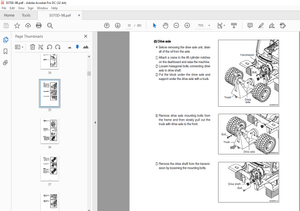
6 8 removing forks
Figure 6-53: Changing forks 6-65
6 9 pivot and sideshift
6 9 1 Tile cylinders 6-66
6 9 2 Crosshead 6-67
Figure 6-54: Hydraulic hoses and electrical connections 6-67
6 9 3 Pivot arm 6-68
Figure 6-55: Secure crosshead / dust covers 6-69
Figure 6-56: Locknut and washer 6-69
Re·-assem bly hints 6-70
6 9 4 Pivot cylinder 6-71
6 9 5 Sideshift assembly 6-71
Sideshift bearing shoe adjust 6-71
Figure 6-57: Sideshift bearing shoe 6-72
Telescoping Slide 6-72
Sideshift chain • 6-73
Figure 6-58: Sideshift chain tension block 6-73
6 10 pump motor
Figure 6-59: Exposing motor connections 6-75
Figure 6-60: Pump/ motor – viewed from underneath truck 6-76
Servicing the motor (hints) • 6-76
Cleaning • • 6-77
Bearings 6-77
Insulation 6-78
6 10 1 Hydraulic pump 6-78
Figure 6-61: Pump/ motor coupling 6-79
Servicing the pump 6-79
Inspection 6-80
Re-assembly hints 6-80
Figure 6-62: Double vs single lip seal 6-81
Figure 6-63: Right vs left hand rotation 6-82
6-6 “SL66/88” Serles Service, Preventive maintenance, p/n: 1421635 -a, 07/02
Corrective maintenance □
Contents – continued Page
6 11 hydraulic control valves
Pivot, shift and tilt 6-82
Figure 6-64: Pivot, shift and tilt valve assembly 6-83
Inspection 6-84
Re-assembly hints 6-85
6 11 1 Lift control valve 6-85
Inspection 6-86
Figure 6-65: Lift Valve Spool Assembly 6-86
Re-assembly hints 6-87
6 12 power steer pump
6 12 1 Removing the pump 6-88
Figure 6-66: Power steering motor/pump location 6-88
Figure 6-67: Electrical connections 6-89
6 12 2 To service the pump 6-89
6 12 3 Orbitrol unit 6-89
Figure 6-68: Sample: Orbitrol assembly 6-90
Figure 6-69: Orbitrol hydraulic lines 6-90
6 12 4 To service the orbitrol 6-90
6 13 electrical system
6 13 1 Compartment door 6-91
Figure 6-70: Electrical panel main and pin connections 6-91
Figure 6-71: Quick disconnect and door clevis pin 6-92
6 13 2 Contactors and coils 6-92
6 13 3 Accelerator module 6-93
Figure 6-72: Driver’s cap floor panel – accelerator access 6-93
Figure 6-73: Accelerator module location 6-93
Potentiometer 6-94
Figure 6-7 4: Potentiometer 6-94
Replacement and adjustment 6-95
Figure 6-75: Replacing switch 6-95
6 14 dash panel
Figure 6-76: Dash panel removal 6-96
Figure 6-77: Panel electrical connectors 6-96
“SL66/77/88” Serles Service, Corrective maintenance, p/n: 1421635-b, 07/03 6-7
□ Corrective maintenance
Contents – continued Page
6 15 pivot & shift
Figure 6-78: Pivot/ shift hydraulic and electrical relationship 6-97
6 15 1 Circuit functions 6-98
Figure 6-79: Shift interlock switch 6-98
Figure 6-80: Extended shift stroke option 6-99
6 15 2 Operation check 6-99
Shift interlock switch 6-99
Figure 6-81: Check shift interlock switch 6-100
Pivot interlock switch 6-101
Figure 6-82: Check pivot interlock switch 6-101
More products