$37
Drexel SL88 Series Base Unit IPB SwingMast Lift Truck Parts Manual 1419553 – PDF
Drexel SL88 Series Base Unit IPB SwingMast Lift Truck Parts Manual 1419553 – PDF DOWNLOAD
FILE DETAILS:
Drexel SL88 Series Base Unit IPB SwingMast Lift Truck Parts Manual 1419553 – PDF DOWNLOAD
Language : English
Pages : 162
Downloadable : Yes
File Type : PDF
IMAGES PREVIEW OF THE MANUAL:
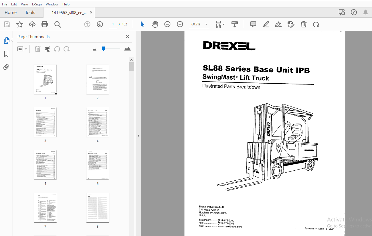
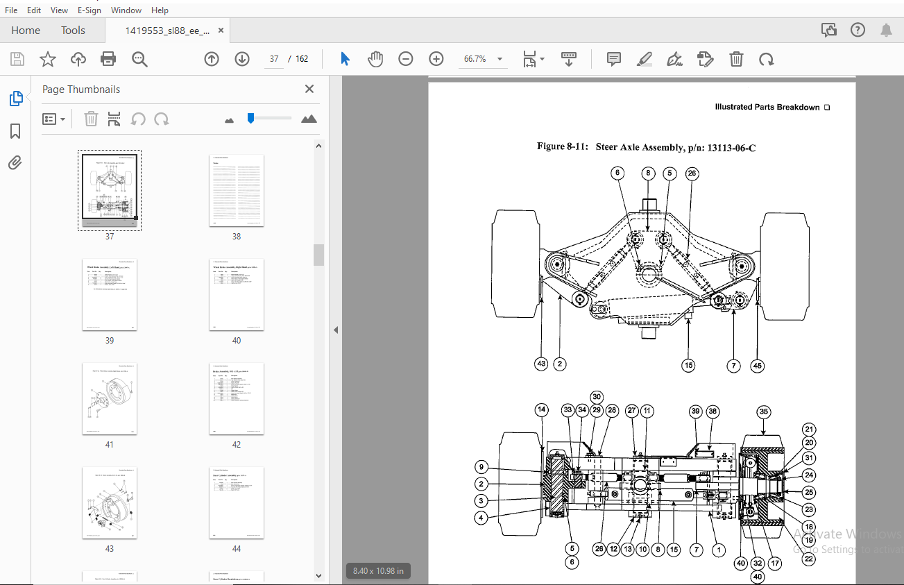
TABLE OF CONTENTS:
Drexel SL88 Series Base Unit IPB SwingMast Lift Truck Parts Manual 1419553 – PDF DOWNLOAD
General 8-5
Abbreviations 8-5
Phantoms / Reference Parts 8-5
Task Groups/Assemblies 8-5
Base Unit, SL88 “EE”, p/n: 1419553-A 8-7
Top Assembly Group, p/n: 13401 8-9
Top Assembly Group, p/n: 13401 (continued) 8-10
Top Assembly Group, p/n: 13401 (continued) 8-11
Top Assembly Group, p/n: 13401 (continued) 8-12
Figure 8-1: Top Assembly Group, p/n: 13401(sheet 1 of 4) 8-13
Figure 8-2: Top Assembly Group, p/n: 13401(sheet 2 of 4) 8-14
Figure 8-3: Top Assembly Group, p/n: 13401(sheet 3 of 4) 8-15
Figure 8-4: Top Assembly Group, p/n: 13401 (sheet 4 of 4) 8-16
Traction Drive Assembly, p/n: 8856-02-K 8-18
Figure 8-5: Traction Drive Assembly, p/n: 8856-02-K 8-19
Traction Motor, p/n: 50298-C 8-20
Figure 8-6: Traction Motor, p/n: 50298-B 8-21
Brake Assembly Modification, p/n: 1406982-B 8-22
Figure 8-7: Brake Assembly Modification, p/n: 1406982-B 8-23
Drive Axle, p/n: 52994-D 8-24
Drive Axle, p/n: 52994-D (continued) 8-25
Drive Axle Assembly, p/n: 52994-D (continued) 8-26
Figure 8-8: Drive Axle Assembly, p/n: 52994 8-27
Differential Assembly, p/n: 20230-A 8-28
Figure 8-9: Differential Assembly, p/n: 20230-A 8-29
Brake Assembly, p/n: 53002-E 8-30
Figure 8-10: Brake Assembly, p/n: 53002-E 8-31
Steer Axle Assembly, pin: 13113-06-C 8-33
Steer Axle Assembly, p/n: 13113-06-C (continued) 8-34
Figure 8-11: Steer Axle Assembly, p/n: 13113-06-C 8-35
Wheel Brake Assembly, Left Hand, pin: 13597-A 8-37
Wheel Brake Assembly, Right Hand, p/n: 13596-A 8-38
Figure 8-12: Wheel Brake Assembly, Right Hand, pin: 13596-A 8-39
Brake Assembly, 10 5 x 2 5, p/n: 18062-D 8-40
Figure 8-13: Brake Assembly, 10 5 x 2 5, p/n: 18062-D 8-41
Steer Cylinder Assembly, p/n: 11171-A 8-42
Figure 8-14: Steer Cylinder Assembly, p/n: 1416946-A 8-43
Steer Cylinder Breakdown, pin: 1416946-A 8-44
Figure 8-15: Steer Cylinder Breakdown, p/n: 1416946-A 8-45
Tie Rod Assembly, p/n: 11158 8-46
Figure 8-16: Tie Rod Assembly, p/n: 11158 8-47
Service Brake System, p/n: 1413804-B 8-49
Service Brake System, p/n: 1413804-B (continued) 8-50
Figure 8-17: Service Brake System, with Knot, p/n: 1413803-B (sheet 1 of 2) 8-51
Figure 8-18: Service Brake System, p/n: 1413803-B (sheet 2 of 2) 8-53
Master Cylinder, 150 PSI Relief, p/n: 1413595-A 8-54
Pump and Motor Assembly, p/n: 9978-B 8-56
Figure 8-19: Pump and Motor Assembly, p/n: 9978-B 8-57
Electric Motor, Pump, pin: 9617-D 8-58
Figure 8-20: Electric Motor, Pump, p/n: 9617-D 8-59
Double Vane Pump, p/n: 21197-D 8-60
Figure 8-21: Double Vane Pump, p/n: 21197-D 8-61
Hydraulic Assembly, p/n: 10550-04-N 8-63
Hydraulic Assembly, p/n: 10550-04-N (continued) 8-64
Hydraulic Assembly, p/n: 10550-04-N (continued) 8-65
Figure 8-22: Hydraulic Assembly, p/n: 10550-04-N (sheet 1 of 4) 8-66
Figure 8-23: Hydraulic Assembly, p/n: 10550-04-N (sheet 2 of 4) 8-67
Figure 8-24: Hydraulic Assembly, p/n: 10550-04-N (sheet 3 of 4) 8-68
Figure 8-25: Hydraulic Assembly, p/n: 10550-04-N (sheet 4 of 4) 8-69
Umbilical Assembly, p/n: 13404-8 8-70
Figure 8-26: Umbilical Assembly, p/n: 13404-B 8-70
Solenoid Valve, SAE 6, 36VDC, p/n: 51199-B 8-71
Figure 8-27: Solenoid Valve, SAE 6, 36VDC, p/n: 51199-B 8-71
Solenoid Valve Breakdown, p/n: 51209-B 8-72
Figure 8-28: Solenoid Valve Breakdown, p/n: 51209-B 8-72
Electrical Panel Assembly, p/n: 16075-05-C 8-73
Electrical Panel Assembly, p/n: 16075-05-B (continued) 8-74
Figure 8-29: Electrical Panel Assembly, p/n: 16075-05-C 8-75
Electrical Door Sub-Assembly, p/n: 1413908-B 8-76
Figure 8-30: Electrical Door Sub-Assembly, p/n: 1413908-B 8-77
Mounting Panel Assembly, p/n: 16076-D 8-78
Figure 8-31: Mounting Panel Assembly, p/n: 16076-D 8-79
SCR Panel, EV-1C, p/n: 50741-B 8-80
Figure 8-32: SCR Panel, EV-1C, p/n: 50741-8 8-81
Contactor, DPDT, 300A, 36VDC, p/n: 28888-D 8-82
Figure 8-33: Contactor, DPDT, 300A, 36VDC, p/n: 28888-D 8-83
Contactor, SPNO, 300A, 36VDC, p/n: 28889-D 8-84
Figure 8-34: Contactor, SPNO, 300A, 36VDC, p/n: 28889-D 8-85
Contactor, 300A, SPNO, 36V, p/n: 1413593-A 8-86
Figure 8-35: Contactor, 300A, SPNO, 36V, pin: 1413593-A 8-87
Power Cable Harness, pin: 16203-D 8-90
Figure 8-36: Power Cable Harness, pin: 16203-D 8-91
Wire Assembly, Curtis Bdi, pin: 1413485-A 8-93
“E” to “EE” Conversion Kit, pin: 16173-C 8-95
Operator’s Compartment, pin: 13018-04-P 8-97
Operator’s Compartment, pin: 13018-04-P (continued) 8-98
Operator’s Compartment, pin: 13018-04-P (continued) 8-99
Figure 8-37: Operator’s Compartment Assembly, pin: 13018-04-P {sheet 1 of 3) 8-101
Figure 8-38: Operator’s Compartment Assembly, pin: 13018-04-P (sheet 2 of 3) 8-102
Figure 8-39: Operator’s Compartment Assembly, pin: 13018-04-P (sheet 3 of 3) 8-103
Accelerator Assembly, pin: 13522-C 8-104
Figure 8-40: Accelerator Assembly, pin: 13522-C 8-105
Accelerator Switch Assembly, pin: 13523-C 8-106
Figure 8-41: Accelerator Switch Assembly, pin: 13523-C 8-107
Reservoir Assembly, pin: 11750-01-B 8-108
Figure 8-42: Reservoir Assembly, pin: 11750-01-B 8-109
Pump and Motor Assembly, pin: 50454-A 8-110
Figure 8-43: Pump and Motor Assembly, pin: 50454-A 8-110
Steering Pump, pin: 50654-A 8-111
Figure 8-44: Steering Pump, pin: 50654-A 8-111
Motor, Steering Pump, pin: 50656-A 8-112
Figure 8-45: Motor, Steering Pump, pin: 50656-A 8-113
Steering Wheel and Horn Assembly, pin: 1410602-A 8-114
Figure 8-46: Steering Wheel and Horn Assembly, pin: 1410602-A 8-115
Dash Panel Assembly, pin: 1402690-C 8-116
Figure 8-47: Dash Panel Assembly, pin: 1402690-B 8-116
Operator’s Control Panel Assembly, pin: 1402667-G 8-118
Figure 8-48: Operator’s Control Panel Assembly, pin: 1402667-H 8-119
Panel Assembly, Key Switch, pin: 16212 8-120
Figure 8-49: Panel Assembly, Key Switch, pin: 16212 8-120
Knob, Pivot, pin: 50382-03 8-122
Knob, Shift, pin: 50382-04 8-122
Knob, Lift, pin: 50382-01 8-122
Knob, Tilt, pin: 50382-02 8-122
Figure 8-50: Knobs, Pivot, Shift, Lift & Tilt, pin: 50382-03, -01, 04, -02 8-123
Control Valve, pin: 22065-B 8-124
Figure 8-51: Control Valve, pin: 22065-B 8-125
Control Valve, 3-way, pin: 23737-C 8-126
Figure 8-52: Control valve, 3-way, pin: 23737-C 8-127
Steering Control Unit, pin: 25763-C 8-128
Figure 8-53: Steering Control Unit, pin: 25763-C 8-129
Intermediate Panel Assembly, pin: 1402716-C 8-130
Figure 8-54: Intermediate Panel Assembly, pin: 1402716-C 8-131
Pump Switch Resistor Assembly, pin: 37887 8-132
Figure 8-55: Pump Switch Resistor Assembly, pin: 37887 8-132
Steer Column, pin: 25040-C 8-133
Figure 8-56: Steer Column, pin: 25040-C 8-133
Battery Connector, Gray SB-350, pin: 25165-A 8-134
Figure 8-57: Battery Connector, Gray SB-350, pin: 25165-A 8-135
Shift Switch Interlock Installation, pin: 13633-8 8-136
Figure 8-58: Shift Switch Interlock Installation, pin: 13633-8 8-137
Driver’s Seat, pin: 1413607-A 8-138
Figure 8-59: Driver’s Seat, pin: 1413607-A 8-139
Pivot Shaft Assembly, pin: 10133-8 8-142
Figure 8-60: Pivot Shaft Assembly, pin: 10133-B 8-143
Pivot Arm Reinforcement, pin: 13475-A 8-145
Side Shift Assembly, pin: 13702-C 8-147
Side Shift Assembly, pin: 13702-C ( continued) 8-148
Figure 8-61: Side Shift Assembly, pin: 13702-C (sheet 1 of 3) 8-149
Figure 8-62: Side Shift Assembly, pin: 13702-C (sheet 2 of 3) 8-150
Figure 8-63: Side Shift Assembly, pin: 13702-C (sheet 3 of 3) 8-151
Shift Cylinder Breakdown, pin: 6790-B 8-152
Figure 8-64: Shift Cylinder Breakdown, pin: 6790-B 8-153
Side Shift Alignment, pin: 66143-A 8-154
Figure 8-65: Side Shift Alignment, pin: 66143-A 8-155
Overhead Guard, pin: 13016-02-D 8-157
Schematics, Electrical and Hydraulic 8-159
More products