$37
Drexel SLT HLT Series Base IPB Tri-lateral Turret Fork Lift Truck Parts Manual 1415206 - PDF DOWNLOA
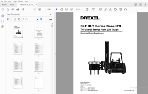
Drexel SLT HLT Series Base IPB Tri-lateral Turret Fork Lift Truck Parts Manual 1415206 - PDF DOWNLOAD
FILE DETAILS:
Drexel SLT HLT Series Base IPB Tri-lateral Turret Fork Lift Truck Parts Manual 1415206 - PDF DOWNLOAD
Language : English
Pages : 266
Downloadable : Yes
File Type : PDF
TABLE OF CONTENTS:
Drexel SLT HLT Series Base IPB Tri-lateral Turret Fork Lift Truck Parts Manual 1415206 - PDF DOWNLOAD
IPB Contents Page
SL T30 "HL T" Turret Base
General 8-9
Abbreviations 8-9
Phantoms / Reference Parts 8-9
Task Groups/Assemblies 8-9
Frame Position and Installation, FR22 8-12
Figure 8-1: Frame Position and Installation, FR22 , 8-13
Drive Unit Sub-Assembly, DAB, 8-16
Figure 8-2: Drive Unit Sub-Assembly, DAB 8-17
Drive Wheel Installation, DA2 8-19
Figure 8-3: Drive Wheel Installation, DA2 8-19
Chain Assembly for Steering, p/n: 1400109-B : 8-20
Figure 8-4: Chain Assembly for Steering, p/n: 1400109-B 8-20
Steer Idler Installation, DA9 8-22
Figure 8-5: Steer Idler Installation, DA9 , 8-23
Lower Drive Unit Installation, DA 11 8-25
Figure 8-6: Lower Drive Unit Installation, DA11 8-25
Drive Motor Installation, DA 12 8-28
Figure 8-7: Drive Motor Installation, DA12 8-29
Drive Unit, Dual Chain, p/n: 1400695-A 8-30
Figure 8-8: Drive Unit, Dual Chain, p/n: 1400695-A 8-33
RearTraction Motor, p/n: 1412772-A 8-34
Figure 8-9: Rear Traction Motor, p/n: 1412772-A 8-35
Steer Idler Assembly, p/n: 1412460-A , 8-36
Figure 8-10: Steer Idler Assembly, p/n: 1412460-A 8-37
Spindle Installation, LW3 8-40
Figure 8-11: Spindle Installation, LW3 , 8-41
Load Wheel Installation, LW6 8-43
Figure 8-12: Load Wheel Installation, LW6 8-43
Load Wheel Sub-Assembly, LW7 , 8-45
Figure 8-13: Wheel Sub-Assembly, LW7 8-45
Service Brake Installation, SB6 , 8-48
Figure 8-14: Service Brake Installation, SB6 , 8-49
Right and Left Brake Assembly, p/n: 51082-01 and -02 8-50
Figure 8-15: Right and Left Brake Assembly, p/n: 51802 -01 and -02 8-51
SLT30 •HL T" Series, Base unit, pin: 1415206-a, 03/01 8-3
□ Table of Contents
IPB Contents - continued Page
Controllers Installation, EL39-A 8-53
Figure 8-16: Controllers Installation, EL39-A 8-55
Control Panel Modification, p/n: 1413417-A 8-56
Figure 8-17: Control Panel Modification, p/n: 1413417-A 8-57
Contactor Panel, p/n: 1413294-A 8-58
Figure 8-18: Contactor Panel, p/n: 1413294-A 8-59
Contactor, 60V, 300A, SPNO, p/n: 1413716 8-60
Figure 8-19: Contactor, 60V, 300A SPNO, p/n: 1413716 8-61
SPNO Contactor, 80V, p/n: 1413939-A 8-62
Figure 8-20: SPNO Contactor, 80V, p/n: 1413939-A 8-63
Portee Mounting Plates, EL28 8-66
Figure 8-21: Portee Mounting Plates, EL28 8-67
Wire Harness Installation, EL32 8-70
Figure 8-22: Wire Harness Installation, EL32 •• 8-71
Portee Sensor Board Installation, EL23 8-74
Figure 8-23: Portee Sensor Board Installation, EL23 8-75
Protec Steer Idler Installation, EL26 8-78
Figure 8-24: Protec Steer Idler Installation, EL26 8-79
Protec Ground Strap Installation, EL24 8-82
Figure 8-25: Protec Ground Strap Installation, EL24 8-83
Battery Connector Sub-Assembly, EL21 : 8-86
Figure 8-26: Battery Connector Sub-Assembly, EL21 8-87
Cable Installation, EL27 8-90
Figure 8-27: Cable Installation, EL27 8-91
Fluids, FL2 8-94
Figure 8-28: Fluids, FL2 , 8-95
Hydraulic Pump and Motor Installation, HY30-A 8-98
Figure 8-29: Hydraulic Pump and Motor Installation, HY30-A 8-99
Hydraulic Pump and Motor Assembly, p/n: 1413611-C 8-100
Figure 8-30: Hydraulic Pump and Motor Assembly, p/n: 1413611-C 8-101
Main Hydraulic Gear Pump, p/n: 1420425-A 8-102
Pump Casappa Field Kit, p/n: 1420681-8 8-102
Figure 8-31: Main Hydraulic Gear Pump, p/n: 1420425-A 8-103
Motor Modification, p/n: 1413625-A 8-105
Figure 8-32: Motor Modification, p/n: 1413625-A 8-105
Electric Motor Breakdown, p/n: 1412771-A 8-106
Figure 8-33: Electric Motor Breakdown, p/n: 1412771-A 8-107
Hydraulic Tank Installation, HY32 8-11 O
Figure 8-34: Hydraulic Tank Installation, HY32 8-111
8-4 SLT30 "HLT" Serles, Base unit, pin: 1415206 ~a, 03/01
Table of Contents D
IPB Contents - continued Page
Hydraulic Tank Sub-Assembly, HY31 , 8-114
Figure 8-35: Hydraulic Tank Sub-Assembly, HY31 8-115
Oil Filter Assembly, p/n: 1412142-A 8-117
Figure 8-36: Oil Filter Assembly, p/n: 1412142-A 8-117
Hydraulic Hose Installation, HY37 8-120
Figure 8-37: Hydraulic Hose Installation, HY37 8-121
Steer Pump/Motor Installation, HY11 8-124
Figure 8-38: Steer Pump/Motor Installation, HY11 8-125
Pump and Motor Assembly, Steering, p/n: 1413444-A 8-126
Figure 8-39: Pump and Motor Assembly, Steering, p/n: 1413444-A 8-127
Steer Pump and Motor Sub-Assembly, HY43 8-129
Figure 8-40: Steer Pump and Motor Sub-Assembly, HY43 8-129
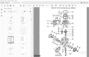
Pump and Motor Assembly, p/n: 1416546-A 8-130
Figure 8-41: Pump and Motor Assembly, Steering, p/n: 1416546-A 8-131
Steering Pump, p/n: 51734 8-133
Figure 8-42: Steering Pump, p/n: 51734 8-133
Steering Motor Assembly, p/n: 51735-01 8-134
Figure 8-43: Steering Motor Assembly, p/n: 51735-01 8-135
Power Steering Hydraulic Installation, HY14 8-137
Figure 8-44: Power Steering Hydraulic Installation, HY14 8-137
Steer Motor Sub-Assembly, HY21 8-140
Figure 8-45: Steer Motor Sub-Assembly, HY21 8-141
Steering Motor Assembly, p/n: 25950 8-142
Figure 8-46: Steering Motor Assembly, p/n: 25950 8-143
Control Valve Installation, HY50 8-145
Figure 8-47: Control Valve Installation, HY50 8-145
Hydraulic Spool Valve Assembly, p/n: 1415064 -D 8-146
Figure 8-48: Hydraulic Spool Valve Assembly, p/n: 1415064-D 8-147
Control Valve Assembly, p/n: 1419760-A 8-148
Control Valve Assembly, p/n: 1419760-A (continued) 8-149
Figure 8-49: Control Valve Assembly Breakdown, p/n: 1419760-A (sheet 1 of 2) 8-150
Figure 8-50: Control Valve Assembly Breakdown, p/n: 1419760-A (sheet 2 of 2) 8-151
Side Console Sub-Assembly, HY57-A 8-154
Figure 8-51: Side Console Sub-Assembly, HY57-A 8-155
Joystick Sub-Assembly, HY56-A 8-158
Figure 8-52: Joystick Hydraulic Sub-Assembly, HY56-A 8-159
Joystick Assembly, p/n: 1406119-A and 1406120-A 8-160
Figure 8-53: Joystick Assembly _ 8-161
Instruments and Side Console Installation, ID7 8-164
Figure 8-54: Instruments and Side Console Installation, ID7 8-165
SLT30 •HLT" Serles, Base unit, p/n: 1415206 ~a, 03/01 8-5
D Table of Contents
IPB Contents - continued Page
Instrument Panel Assembly, p/n: 1413726-8 8-166
Figure 8-55: Instrument Panel Assembly, p/n: 1413726-8 8-167
Side Console Installation, OH10 8-170
Figure 8-56: Side Console Installation, OH10 8-171
Steering Wheel Installation, ID4 8-173
Figure 8-57: Steering Wheel Installation, ID4 8-173
Horn Button Installation, OH2 8-176
Figure 8-58: Horn Button Installation, OH2 8-177
Operator Console Installation, OH6 8-179
Figure 8-59: Operator Console Installation, OH6 8-179
Steering Column Installation, HY5 8-181
Figure 8-60: Steer Column Installation, HY5 8-181
Steering Column Assembly, p/n: 1400968-D 8-183
Figure 8-61: Steering Column Assembly, p/n: 1400968-D 8-183
Steering Control Assembly, p/n: 25975-C 8-184
Figure 8-62: Steering Control Assembly, p/n: 25975-C 8-185
Key Switch Installation, EL 14 8-187
Figure 8-63: Key Switch Installation, EL 14 8-187
Key Switch Assembly, p/n: 1404722-C 8-188
Figure 8-64: Key Switch Assembly, p/n: 1404722-C 8-188
Brake Weldment Assembly, SB2 8-190
Figure 8-65: Brake Weldment Assembly, SB2 8-191
Brake Pedal Installation, SB3 8-194
Figure 8-66: Brake Pedal Installation, SB3 • 8-195
Master Cylinder Installation, SB4 8-198
Figure 8-67: Master Cylinder Installation, SB4 8-199
Master Cylinder Assembly, p/n: 1402557-C 8-200
Figure 8-68: Master Cylinder Assembly, p/n: 1402557-C 8-201
Accelerator Unit Installation, EL 15 8-203
Figure 8-69: Accelerator Unit Installation, EL 15 8-203
Parking Brake Installation, PBS 8-206
Figure 8-70: Parking Brake Installation, PBS 8-207
Parking Brake Installation, PB17 8-210
Figure 8-71: Parking Brake Installation, PB17 8-211
Brake Cable Installation, PB4 8-214
Figure 8-72: Brake Cable Installation, PB4 8-215
Equalizer Installation, PB2 8-218
Figure 8-73: Equalizer Installation, PB2 8-219
Seat Belt Installation, ST1 (serial# 1797 and before) 8-221
Figure 8-74: Seat Belt Installation, ST1 8-221
8-6 SLT3D"HLT"Serles, Baseunft,p/n:1415206-a, 03/01
Table of Contents D
IPB Contents - continued Page
Seat Installation, ST2 (serial# 1797 and before) 8-224
Figure 8-75: Seat Installation, ST2 8-225
Seat Assembly, p/n: 1413058-A (serial# 1797 and before) 8-226
Figure 8-76: Driver's Seat Assembly, p/n: 1413058-A 8-226
Stack Valve Cover, 106 8-228
Figure 8-77: Stack Valve Cover, 106 8-229
Rear Compartment Seal, 1012 8-232
Figure 8-78: Rear Compartment Seal, 1012 8-233
Battery Door Installation, OH11 8-236
Figure 8-79: Battery Door Installation, OH11 8-237
Battery Door Sub-Assembly, OH13 8-240
Figure 8-80: Battery Door Sub-Assembly, OH13 8-241
Side Cover Weldment Installation, 1013 8-244
Figure 8-81: Side Cover Weldment Installation, 1013 8-245
Console Cover Sub-Assembly, OH9 8-247
Figure 8-82: Console Cover Sub-Assembly, OH9 8-247
Rear Compartment Cover, C03 8-250
Figure 8-83: Rear Compartment Covers, C03 8-251
Floor Plate Installation, OH3 8-253
Figure 8-84: Floor Plate Installation, OH3 8-253
Floor Plate Sub-Assembly, CO2 8-255
Figure 8-85: Floor Plate Sub-Assembly, CO2 8-255
Overhead Guard Installation, OH1 8-258
Figure 8-86: Overhead Guard Installation, OH1 8-259
Identification Labeling, 1014 8-262
Figure 8-87: Identification Labeling, 1014 (sheet 1 of 2) 8-263
Figure 8-88: Identification Labeling, 1014 (sheet 2 of 2) 8-265
Schematics and Diagrams 8-267
IMAGES PREVIEW OF THE MANUAL:
More products