$39
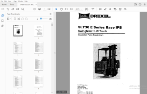
Drexel SLT30 E Series Base IPB SwingMast Lift Truck Parts Manual 1417751 - PDF DOWNLOAD
Drexel SLT30 E Series Base IPB SwingMast Lift Truck Parts Manual 1417751 - PDF DOWNLOAD
FILE DETAILS:
Drexel SLT30 E Series Base IPB SwingMast Lift Truck Parts Manual 1417751 - PDF DOWNLOAD
Language : English
Pages : 322
Downloadable : Yes
File Type : PDF
TABLE OF CONTENTS:
Drexel SLT30 E Series Base IPB SwingMast Lift Truck Parts Manual 1417751 - PDF DOWNLOAD
SL T30 "E" Series IPB
General 8-9
Abbreviations 8-9
Phantoms / Reference Parts 8-9
Task Groups/Assemblies 8-9
Frame Position and Installation, p/n: FR15-A 8-11
Figure 8-1: Frame Position and Installation, p/n: FR15-A 8-13
Frame Bearings Installation, p/n: FR17-A 8-15
Figure 8-2: Frame Bearings Installation, p/n: FR17-A 8-15
Drive Motor Installation, DA12-C 8-18
Figure 8-3: Drive Motor Installation, DA 12-C -:: • 8-19
Drive Unit, Dual Chain, p/n: 1400695-A 8-20
Figure 8-4: Drive Unit, Dual Chain, p/n: 1400695-A 8-23
Traction Motor, Rear Drive, p/n: 1400694-A 8-24
Figure 8-5: Traction Motor, Rear Drive, p/n: 1400694-A 8-25
Steer Idler Assembly, p/n: 1412460-A 8-26
Figure 8-6: Steer Idler Assembly, p/n: 1412460-A 8-27
Drive Unit Sub-Assembly, DAB 8-30
Figure 8-7: Drive Unit Sub-Assembly, DAB 8-31
Chain Assembly for Steering, p/n: 1400109-8 8-32
Figure 8-8: Chain Assembly for Steering, p/n: 1400109-B 8-32
Drive Wheel Installation, DA2-A 8-33
Figure 8-9: Drive Wheel Installation, DA2-A 8-33
Steer Idler Installation, DA9-A 8-36
Figure 8-10: Steer Idler Installation, DA9-A 8-37
Lower Drive Unit Installation, DA 11-A 8-39
Figure 8-11: Lower Drive Unit Installation, DA11-A 8-39
Press Drive Plate Studs, DA14 8-41
Figure 8-12: Press Drive Plate Studs, DA14 8-41
Spindle Installation, L W3-B 8-44
Figure 8-13: Spindle Installation, LW3-B 8-45
Load Wheel Installation, LW6-B 8-47
Figure 8-14: Load Wheel Installation, LW6-B 8-47
Load Wheel Sub-Assembly, LW7-A 8-49
Figure 8-15: Wheel Sub-Assembly, LW7-A 8-49
SLT30 •E• Series, Base Unit, pin: 1417751-b, 02/03 8-3
D Table of Contents
IPB Contents - continued Page
Service Brake Installation, SB5 8-52
Figure 8-16: Service Brake Installation, SB5 8-53
Right & Left Brake Assembly, p/n: 51082-01 & -02 8-54
Figure 8-17: Right & Left Brake Assembly, p/n: 51802 -01 & -02 8-55
Controller Installation, EL41-A 8-57
Figure 8-18: Controllers Installation, EL41-A 8-57
Control Panel Modification, p/n: 1413417-A 8-58
Figure 8-19: Control Panel Modification, p/n: 1413417-A 8-59
Contactor Panel, p/n: 1413294-A 8-61
Figure 8-20: Contactor Panel, p/n: 1413294-A 8-61
Contactor, 60V, 300A, SPNO, p/n: 1413716 8-62
Figure 8-21: Contactor, 60V, 300A SPNO, p/n: 1413716 8-63
SPNO Contactor, 80V, p/n: 1413939 - A 8-64
Figure 8-22: SPNO Contactor, 80V, p/n: 1413939-A 8-65
Battery Connector Sub-Assembly, EL 17-B 8-68
Figure 8-23: Battery Connector Sub-Assembly, EL 17~8 8-69
Wire Harness Installation, EL 18~8 8-72
Figure 8-24: Wire Harness Installation, EL 18-B 8-73
Cable Installation, EL 19-A 8-75
Figure 8-25: Cable Installation, EL 19-A 8-75
Ground Straps Installation, p/n: EL38-B 8-77
Figure 8-26: Ground Straps Installation, p/n: EL38-B 8-77
Fluids, FL 1 8-80
Figure 8-27: Fluids, FL 1 8-81
Hydraulic Pump/Motor Installation, HY52-A 8-84
Figure 8-28: Hydraulic Pump/Motor Installation, HY52-A 8-85
Hydraulic Pump/Motor Assembly, p/n: 1413611-C 8-86
Figure 8-29: Hydraulic Pump/Motor Assembly, p/n: 1413611-C 8-87
Main Hydraulic Gear Pump, p/n: 1420425-A 8-88
Pump Casappa Field Kit, p/n: 1420681-B 8s88
Figure 8-30: Main Hydraulic Gear Pump, p/n: 1420425-A 8-89
Main Motor Assembly, p/n: 1412771-A 8-90
Figure 8-31: Main Motor Assembly, p/n: 1412771-A 8-91
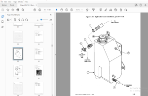
Hydraulic Tank Installation, p/n: HY74-A 8-94
Figure 8-32: Hydraulic Tank Installation, p/n: HY74-A 8-95
Hydraulic Reservoir, p/n: 1419896-C 8-96
Figure 8-33: Hydraulic Reservoir, p/n: 1419896-C 8-97
Oil Filter, Return Line, p/n: 1419880-A 8-98
Figure 8-34: Oil Filter, Return Line, p/n: 1419880-A 8-98
Hydraulic Hose Installation, HY23 8-100
Figure 8-35: Hydraulic Hose Installation, HY23 8-101
8-4 SLT30 ~E~ Serles, Base Unit, p/n: 1417751 -b, 02/03
Table of Contents D
IPB Contents - continued Page
Side Shift Hose, HY7 8-103
Figure 8-36: Side Shift Hose, HY7 8-103
Umbilical Assembly Installation, HY8 8-1-06
Figure 8-37: Umbilical Assembly Installation, HY8 8-107
Umbilical Tray Installation, HY22 8-11 O
Figure 8-38: Umbilical Tray Installation, HY22 8-111
Umbilical Hoses Connect, HY46 8-114
Figure 8-39: Umbilical Hoses Connect, HY46 8-115
Manifold Assembly, p/n: 1413172-C 8-116
Figure 8-40: Manifold Assembly, p/n: 1413172-C 8-117
Pivot and Tilt Hose Installation, HY19 8-120
Figure 8-41: Pivot and Tilt Hose Installation, HY19 8-121
Orbitrol Tank Hose Installation, HY48 8-124
Figure 8-42: Orbitrol Tank Hose Installation, HY48 8-125
Steer Pump and Motor Installation, HY11-A 8-128
Figure 8-43: Steer Pump/Motor Installation, HY11-A :-8-129
Steer Pump/Motor Sub-Assembly, HY12 8-131
Figure 8-44: Steer Pump/Motor Sub-Assembly, HY12 8-131
Steering Pump, p/n: 51734 8-133
Figure 8-45: Steering Pump, p/n: 51734 8-133
Steering Motor Assembly, p/n: 51735 8-134
Figure 8-46: Steering Motor ,Assembly, p/n: 51735 8-135
Power Steering Hydraulic Installation, HY14-B 8-137
Figure 8-47: Power Steering Hydraulic Installation, HY14-B 8-137
Steer Motor Sub-Assembly, HY21-A 8-140
Figure 8-48: Steer Motor Sub-Assembly, HY21-A 8-141
Steering Motor Assembly, p/n: 25950-A 8-142
Figure 8-49: Steering Motor Assembly, p/n: 25950-A 8-143
Control Valve Installation, p/n: HY15-D 8-145
Figure 8-50: Control Valve Installation, p/n: HY15-D 8-145
Hydraulic Spool Valve Assembly, p/n: 1415064 -D 8-146
Figure 8-51: Hydraulic Spool Valve Assembly, p/n: 1415064-D 8-147
Control Valve Assembly, p/n: 1419760-A 8-148
Control Valve Assembly, p/n: 1419760-A (continued) 8-149
Figure 8-52: Control Valve Assembly Breakdown, p/n: 1419760-A (sheet 1 of 2) 8-150
Figure 8-53: Control Valve Assembly Breakdown, p/n: 1419760-A (sheet 2 of 2) 8-151
Joystick Installation, HY20 8-154
Figure 8-54: Joystick Installation, HY20 8-155
Joystick Hydraulic Sub-Assembly, HY24 8-157
Figure 8-55: Joystick Hydraulic Sub-Assembly, HY24 8-157
Joystick Assembly, p/n: 1406119-A and 1406120-A 8-158
Figure 8-56: Joystick Assembly 8-159
SLT30 ·E• Series, Base Uni~ pin: 1417751 ~b, 02/03 8-5
□ Table of Contents
IPB Contents - continued Page
Instruments and Side Console Installation, ID3-D 8-162
Figure 8-57: Instruments and Side Console Installation, ID3 8-163
Instrument Panel Assembly, p/n: 1413057-D 8-164
Figure 8-58: Instrument Panel Assembly, p/n: 1413057-D 8-165
Cover Plate Assembly, Standard, p/n: 1401930-C 8-166
Figure 8-59: Cover Plate Assembly, Standard, p/n: 1401930-C 8-166
Side Console Installation, OH7 8-168
Figure 8-60: Side Console Installation, OH7 8-169
Console Cover Sub-Assembly, OH9-B 8-171
Figure 8-61: Console Cover Sub-Assembly, OH9-B 8-171
Steering Wheel Installation, ID4-A 8-173
Figure 8-62: Steering Wheel Installation, ID4-A 8-173
Horn Button Installation, OH2-A 8-176
Figure 8-63: Horn Button Installation, OH2-A 8-177
Operator Console Installation, OH6-A : 8-179
Figure 8-64: Operator Console Installation, OH6-A 8-179
Steering Column Installation, HY5-B 8-181
Figure 8-65: Steer Column Installation, HY5-B 8-181
Steering Column Assembly, p/n: 1400968-D 8-183
Figure 8-66: Steering Column Assembly, p/n: 1400968-D 8-183
Steering Control Assembly, p/n: 25975-C 8-184
Figure 8-67: Steering Control Assembly, p/n:25975-C 8-185
Key Switch Installation, EL 14-A 8-187
Figure 8-68: Key Switch Installation, EL 14-A 8-187
Brake Weldment Assembly, SB2-A 8-190
Figure 8-69: Brake Weldment Assembly, SB2-A 8-191
Brake Pedal Installation, SB3-B 8-194
Figure 8-70: Brake Pedal Installation, SB3-B , 8-195
Master Cylinder Installation, SB4-A 8-198
Figure 8-71: Master Cylinder Installation, SB4-A 8-199
Master Cylinder Assembly, p/n: 1402557-C 8-200
Figure 8-72: Master Cylinder Assembly, p/n: 1402557-C 8-201
Accelerator Unit Installation, EL 15-A 8-203
Figure 8-73: Accelerator Unit Installation, EL 15-A 8-203
Parking Brake Installation, PB17-C 8-206
Figure 8-74: Parking Brake Installation, PB17-C 8-207
Parking Brake Sub-Assembly, PB1 8-210
Figure 8-75: Parking Brake Sub-Assembly, PB1 8-211
Equalizer Installation, PB2-A 8-214
Figure 8-76: Equalizer Installation, PB2-A 8-215
Brake Cable Installation, PB3 8-218
Figure 8-77: Brake Cable Installation, PB3 8-219
8-6 SLT30 "E• Series, Base Unit, pin: 1417751 -b, 02/03
Table of Contents D
IPB Contents - continued Page
Brake Cable, 113" OAL, p/n: 1400532-A 8-220
Brake Cable, 135" OAL, p/n: 1400533-A 8-220
Figure 8-78: Brake Cable Assembly 8-221
Seat Belt Installation, ST1-A 8-223
Figure 8-79: Seat Belt Installation, ST1-A 8-223
Seat Installation, ST2-D 8-226
Figure 8-80: Seat Installation, ST2-D 8-227
Seat Assembly, p/n: 1413058-A 8-228
Figure 8-81: Driver's Seat Assembly, p/n: 1413058-A 8-229
Driver's Seat Group, p/n: 1420373-A (serial# 1798 & future) 8-231
Figure 8-82: Seat Group p/n: 1420373-A 8-231
Driver's Seat Breakdown, p/n: 1420374-A 8-232
Figure 8-83: Driver's Seat Breakdown, p/n: 1420374-A 8-233
Lower Bar Installation, PSS-A 8-236
Figure 8-84: Lower Bar Installation, PSS-A 8-237
Lower Bar Sub-Assembly, PS7-A 8-239
Figure 8-85: Lower Bar Sub-Assembly, PS7-A 8-239
Pivot and Shift Installation, PS10-8 8-242
Figure 8-86: Pivot and Shift Installation, PS10-8 8-243
Pivot and Shift Chain Anchor Installation, PS20-C 8-245
Figure 8-87: Pivot and Shift Chain Anchor Installation, PS20-C 8-245
Shift Cylinder Installation, PS6-B 8-248
Figure 8-88: Shift Cylinder Installation, PS6-B 8-249
Shift Cylinder Sub-Assembly, PS9-C 8-252
Figure 8-89: Shift Cylinder Sub-Assembly, PS9-C 8-253
Shift Cylinder Breakdown, p/n: 1422514-A 8-254
Figure 8-90: Shift Cylinder Breakdown, p/n: 1422514-A 8-255
Side Shift Chains Installation, PSS-A 8-258
Figure 8-91: Side Shift Chains Installation, PSS-A 8-259
Cross Head Bearings Installation, PS1-A 8-262
Figure 8-92: Cross Head Bearings Installation, PS1-A 8-263
Pivot Arm Installation, PS2-A 8-266
Figure 8-93: Pivot Arm Installation, PS2-A 8-267
Pivot Stop Pad Installation, PS3-B 8-270
Figure 8-94: Pivot Stop Pad Installation, PS3-B 8-271
Pivot Cylinder Installation, PS4-A 8-274
Figure 8-95: Pivot Cylinder Installation, PS4-A 8-275
Pivot Cylinder Assembly, p/n; 1400601-A 8-276
Figure 8-96: Pivot Cylinder Assembly, p/n; 1400601-A 8-277
SLT30 ~E" Serles, Base Uni~ pin: 1417751 Mb, 02/03 8-7
□ Table of Contents
IPB Contents - continued Page
Tilt Cylinder Installation, MA52-B 8-280
Figure 8-97: Tile Cylinder Installation, MA52-B 8-281
Tilt Cylinder Breakdown, p/n: 1422314-A 8-282
Figure 8-98: Tilt Cylinder Assembly, p/n: 1422314-A 8-283
Stack Valve Cover, ID5 8-285
Figure 8-99: Stack Valve Cover, ID5 8-285
Rear Compartment Seal, ID8 8-288
Figure 8-100: Rear Compartment Seal, ID8 8-289
Battery Door Installation, OH4 8-291
Figure 8-101: Battery Door Installation, OH4 8-291
Battery Door Sub-Assembly, OH8 8-294
Figure 8-102: Battery Door Sub-Assembly, OH8 , 8-295
Side Cover Weldrnent Installation, ID9 8-298
Figure 8-103: Side Cover Weldment Installation, ID9 8-299
Rear Co,mpartment Cover, C01 8-302
Figure 8-104: Rear Compartment Covers, CO1 8-303
Floor Plate Installation, OH3 8-305
Figure 8-105: Floor Plate Installation, OH3 8-305
Floor Plate Sub-Assembly, CO2-A 8-307
Figure 8-106: Floor Plate Sub-Assembly, CO2-A 8-307
Mast Level Indicator Installation, MA2 8-309
Figure 8-107: Mast Level Indicator Installation, MA2 8-309
Overhead Guard Installation, OH1-A 8-312
Figure 8-108: Overhead Guard Installation, OH1-A 8-313
Identification Labeling, ID15-B 8-315
Figure 8-109: Identification Labeling, ID15-B 8-316
Figure 8-110: Identification Labeling, ID15-B 8-317
Schematics and Drawings 8-319
Figure 8-111: Schematics and Drawings (sheet 1 of 2) 8-320
Figure 8-112: Schematics and Drawings (sheet 2 of 2) 8-321
IMAGES PREVIEW OF THE MANUAL:
S.S 05/24
More products