$40
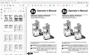
Drexel SLT30 EE Series Base IPB SwingMast Lift Truck Parts Manual 1422753 - PDF DOWNLOAD
Drexel SLT30 EE Series Base IPB SwingMast Lift Truck Parts Manual 1422753 - PDF DOWNLOAD
FILE DETAILS:
Drexel SLT30 EE Series Base IPB SwingMast Lift Truck Parts Manual 1422753 - PDF DOWNLOAD
Language : English
Pages : 304
Downloadable : Yes
File Type : PDF
TABLE OF CONTENTS:
Drexel SLT30 EE Series Base IPB SwingMast Lift Truck Parts Manual 1422753 - PDF DOWNLOAD
IPB Contents Page
SLT30 "EE" Series Base IPB
General 8-9
Abbreviations 8-9
Phantoms / Reference Parts 8-9
Task Groups/Assemblies 8-9
Frame Position and Installation, p/n: FR15-A 8-11
Figure 8-1: Frame Position and Installation, p/n: FR15-A 8-13
Frame Bearings Installation, p/n: FR17-A 8-15
Figure 8-2: Frame Bearings Installation, p/n: FR17-A 8-15
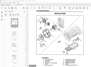
Drive Motor Installation, DA12-C 8-18
Figure 8-3: Drive Motor Installation, DA12-C :8-19
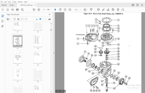
Drive Unit, Dual Chain, p/n: 1400695-A 8-20
Figure 8-4: Drive Unit, Dual Chain, p/n: 1400695-A , 8-23
Traction Motor, Rear Drive, p/n: 1400694-A 8-24
Figure 8-5: Traction Motor, Rear Drive, p/n: 1400694-A 8-25
Steer Idler Assembly, p/n: 1412460-A 8-26
Figure 8-6: Steer Idler Assembly, p/n: 1412460-A 8-27
Drive Unit Sub-Assembly, DAB 8-30
Figure 8-7: Drive Unit Sub-Assembly, DAB 8-31
Chain Assembly for Steering, p/n: 1400109-B 8-32
Figure 8-8: Chain Assembly for Steering, p/n: 1400109-B 8-32
Drive Wheel Installation, DA2-A 8-33
Figure 8-9: Drive Wheel Installation, DA2-A 8-33
Steer Idler Installation, DA9-A 8-36
Figure 8-10: Steer Idler Installation, DA9-A 8-37
Lower Drive Unit Installation, DA 11-A 8-39
Figure 8-11: Lower Drive Unit Installation, DA 11-A 8-39
Press Drive Plate Studs, DA14 8-41
Figure 8-12: Press Drive Plate Studs, DA14 8-41
Spindle Installation, LW3-B 8-44
Figure 8-13: Spindle Installation, LW3-B 8-45
Load Wheel Installation, LW6-B 8-47
Figure 8-14: Load Wheel Installation, LW6-B 8-47
SLT30 •EE" Serles, Base Unit, pin: 1422753 -a, 10/03 8-3
Table of Contents D
IPB Contents - continued Page
Load Wheel Sub-Assembly, LW7-A 8-49
Figure 8-15: Wheel Sub-Assembly, LW7-A 8-49
Service Brake Installation, SB5 8-52
Figure 8-16: Service Brake Installation, SB5 8-53
Right & Left Brake Assembly, p/n: 51082-01 & -02 : 8-54
Figure 8-17: Right & Left Brake Assembly, pin: 51802 -01 & -02 8-55
Fluids, FL 1 8-58
Figure 8-18: Fluids, FL 1 8-59
Hydraulic Pump/Motor Installation, HY52-A 8-62
Figure 8-19: Hydraulic Pump/Motor Installation, HY52-A 8-63
Hydraulic Pump/Motor Assembly, p/n: 1413611-C 8-64
Figure 8-20: Hydraulic Pump/Motor Assembly, p/n: 1413611-C 8-65
Main Hydraulic Gear Pump, p/n: 1420425-A 8-66
Pump Casappa Field Kit, p/n: 1420681-8 8-66
Figure 8-21: Main Hydraulic Gear Pump, p/n: 1420425-A 8-67
Main Motor Assembly, p/n: 1412771-A 8-68
Figure 8-22: Main Motor Assembly, pin: 1412771-A 8-69
Hydraulic Tank Installation, p/n: HY74-A , 8-72
Figure 8-23: Hydraulic Tank Installation, p/n: HY74-A 8-73
Hydraulic Reservoir, p/n: 1419896-C 8-74
Figure 8-24: Hydraulic Reservoir, p/n: 1419896-C 8-75
Oil Filter, Return Line, p/n: 1419880-A 8-76
Figure 8-25: Oil Filter, Return Line, p/n: 1419880-A 8-76
HydraulicHose Installation, HY23 ; 8-78
Figure 8-26: Hydraulic Hose Installation, HY23 8-79
Side Shift Hose, HY7 8-81
Figure 8-27: Side Shift Hose, HY7 8-81
Umbilical Assembly Installation, HY8 : 8-84
Figure 8-28: Umbilical Assembly Installation, HY8 8-85
Umbilical Tray Installation, HY22 8-88
Figure 8-29: Umbilical Tray Installation, HY22 8-89
Umbilfcal Hoses Connect, HY 46 8-92
Figure 8-30: Umbilical Hoses Connect, HY46 8-93
Manifold Assembly, p/n: 1413172-C , 8-94
Figure 8-31: Manifold Assembly, p/n: 1413172-C 8-95
Pivot and Tilt Hose Installation, HY19 8-98
Figure 8-32: Pivot and Tilt Hose Installation, HY19 8-99
Orbitrol Tank Hose Installation, HY48 8-102
Figure 8-33: Orbitrol Tank Hose Installation, HY48 8-103
Steer Pump and Motor Installation, HY11-A 8-106
Figure 8-34: Steer Pump/Motor Installation, HY11-A 8-107
SLT30 •EE" Serles, Base Unit, pin: 1422753-a, 10/03 8-4
Table of Contents □
IPB Contents - continued Page
Steer Pump/Motor Sub-Assembly, HY12 8-109
Figure 8-35: Steer Pump/Motor Sub-Assembly, HY12 • 8-109
Steering Pump, p/n: 51734 , 8-111
Figure 8-36: Steering Pump, p/n: 51734 • 8-111
Steering Motor Assembly, p/n: 51735 8-112
Figure 8-37: Steering Motor Assembly, p/n: 51735 8-113
Power Steering Hydraulic Installation, HY14-B 8-115
Figure 8-38: Power Steering Hydraulic Installation, HY14-B 8-115
Steer Motor Sub-Assembly, HY21-A 8-118
Figure 8-39: Steer Motor Sub-Assembly, HY21-A 8-119
Steering Motor Assembly, p/n: 25950-A , • 8-120
Figure 8-40: Steering Motor Assembly, p/n: 25950-A 8-121
Control Valve Installation, p/n: HY15-D 8-123
Figure 8-41: Control Valve Installation, p/n: HY15-D 8-123
Hydraulic Spool Valve Assembly, p/n: 1415064 -D 8-124
Figure 8-42: Hydraulic Spool Valve Assembly, p/n: 1415064-D 8-125
Control Valve Assembly, p/n: 1419760-A 8c126
Control Valve Assembly, p/n: 1419760-A (continued) 8-127
Figure 8-43: Control Valve Assembly Breakdown, p/n: 1419760-A (sheet 1 of 2) 8-128
Figure 8c44: Control Valve Assembly Breakdown, p/n: 1419760-A (sheet 2 of 2) • 8-129
Joystick Installation, HY20 8-132
Figure 8-45: Joystick Installation, HY20 8-133
Joystick Hydraulic Sub-Assembly, HY24 8-135
Figure 8-46: Joystick Hydraulic Sub-Assembly, HY24 8-135
Joystick Assembly, p/n: 1406119-A and 1406120-A 8-136
Figure 8-47: Joystick Assembly 8-137
Instruments and Side Console Installation, 1D3 8-140
Figure 8-48: Instruments and Side Console Installation, 1D3 8-141
Instrument Panel Assembly, p/n: 1413057-D 8-142
Figure 8-49: Instrument Panel Assembly, p/n: 1413057-D 8-143
Cover Plate Assembly, Standard, p/n: 1401930-C 8-144
Figure 8-50: Cover Plate Assembly, Standard, p/n: 1401930-C 8-144
Side Console Installation, OH? 8-146
Figure 8-51: Side Console Installation, OH? • 8-147
Console Cover Sub-Assembly, OH9-B 8-149
Figure 8-52: Console Cover Sub-Assembly, OH9-B 8-149
Steering Wheel Installation, 1D4-A 8-151
Figure 8-53: Steering Wheel Installation, 1D4-A 8-151
Horn Button Installation, OH2-A 8-154
Figure 8-54: Horn Button Installation, OH2-A 8-155
SLT30 ~EE' Series, Base Unit, p/n: 1422753 -a, 10/03 8-5
Table of Contents D
IPB Contents - continued Page
Operator Console Installation, OH6-A 8-157
Figure 8-55: Operator Console Installation, OH6-A 8-157
Steering Column Installation, HY5-B 8-159
Figure 8-56: Steer Column Installation, HY5-B 8-159
Steering Column Assembly, p/rn 1400968-D 8-161
Figure 8-57: Steering Column Assembly, p/n: 1400968-D 8-161
Steering Control Assembly, p/n: 25975-C 8-162
Figure 8-58, Steering Control Assembly, p/n: 25975-C 8-163
Key Switch Installation, EL 14-A 8-165
Figure 8-59: Key Switch Installation, EL 14-A 8-165
Brake Weldment Assembly, SB2-A • 8-168
Figure 8-60: Brake Weldment Assembly, SB2-A 8-169
Brake Pedal Installation, SB3-B 8-172
Figure 8-61: Brake Pedal Installation, SB3-B 8-173
Master Cylinder Installation, SB4-A : 8-176
Figure 8-62: Master Cylinder Installation, SB4-A , 8-177
Master Cylinder Assembly, p/n: 1402557-C 8-178
Figure 8-63: Master Cylinder Assembly, p/n: 1402557-C 8-179
Accelerator Unit Installation, EL 15-A : 8-181
Figure 8-64: Accelerator Unit Installation, EL 15-A 8-181
Parking Brake Installation, PB17-C 8-184
Figure 8-65: Parking Brake Installation, PB17-C 8-185
Parking Brake Sub-Assembly, PB1 8-188
Figure 8-66: Parking Brake Sub-Assembly, PB1 8-189
Equalizer Installation, PB2-A 8-192
Figure 8-67: Equalizer Installation, PB2-A 8-193
Brake Cable Installation, PB3 8-196
Figure 8-68: Brake Cable Installation, PB3 8-197
Brake Cable, 113" OAL, p/n: 1400532-A ; 8-198
Brake Cable, 135" OAL, p/n: 1400533-A 8-198
Figure 8-69: Brake Cable Assembly : 8-199
Driver's Seat, Vinyl 8-202
Seat Belt Installation, ST1 (serial# 1797 and before) , • , 8-202
Figure 9-70: Seat Belt Installation, ST1 8-203
Seat Installation, for Seat Assembly 1412660 8-204
Figure 9-71: Seat Installation, for Seat Assembly 1412660 8-205
Seat Installation, for Seat Assembly 1413715 8-206
Figure 9-72: Seat Installation, for Seat Assembly 1413715 • 8-207
Driver's Seat Breakdown 8-208
Figure 9-73: Driver's Seat Breakdown 8-209
Seat Installation, ST2-D 8-212
Figure 8-74: Seat Installation, ST2-D 8-213
SLT30 •EE" Serles, Base Unit, pin: 1422753 ~a, 10/03 8-6
Table of Contents El
IPB Contents - continued Page
Seat Assembly, p/n: 1413058-A 8-214
Figure 8-75: Driver's Seat Assembly, p/n: 1413058-A 8-215
Lower Bar Installation, PSS-A 8-218
Figure 8-76: Lower Bar Installation, PSS-A , 8-219
Lower Bar Sub-Assembly, PS7-A , 8-221
Figure 8-77: Lower Bar Sub-Assembly, PS7-A 8-221
Pivot and Shift Installation, PS10-B , 8-224
Figure 8-78: Pivot and Shift Installation, PS10-B 8-225
Pivot and Shift Chain Anchor Installation, PS20-C 8-227
Figure 8-79: Pivot and Shift Chain Anchor Installation, PS20-C 8-227
Shift Cylinder Installation, PS6-B 8-230
Figure 8-80: Shift Cylinder Installation, PS6-B 8-231
Shift Cylinder Sub-Assembly, PS9-C 8-234
Figure 8-81: Shift Cylinder Sub-Assembly, PS9-C 8-235
Shift Cylinder Breakdown, p/n: 1422514-A 8-236
Figure 8-82: Shift Cylinder Breakdown, p/n: 1422514-A 8-237
Side Shift Chains Installation, PS5-A 8-240
Figure 8-83: Side Shift Chains Installation, PS5-A 8-241
Cross Head Bearings Installation, PS1-A : 8-244
Figure 8-84: Cross Head Bearings Installation, PS1-A 8-245
Pivot Stop Pad Installation, PS3-B 8-248
Figure 8-85: Pivot Stop Pad Installation, PS3-B 8-249
Pivot Arm Installation, PS2-A 8-252
Figure 8-86: Pivot Arm Installation, PS2-A 8-253
Pivot Cylinder Installation, PS4-A 8-256
Figure 8-87: Pivot Cylinder Installation, PS4-A 8-257
Pivot Cylinder Assembly, p/n; 1400601-A 8-258
Figure 8-88: Pivot Cylinder Assembly, p/n; 1400601-A 8-259
Tilt Cylinder Installation, MA52-B 8-262
Figure 8-89: Tile Cylinder Installation, MA52-B 8-263
Tilt Cylinder Breakdown, p/n: 1422314-A 8-264
Figure 8-90: Tilt Cylinder Assembly, p/n: 1422314-A 8-265
Stack Valve Cover, ID5 8-267
Figure 8-91: Stack Valve Cover, IDS 8-267
Rear Compartment Seal, IDB 8-270
Figure 8-92: Rear Compartment Seal, IDB 8-271
Battery Door Installation, OH4 8-273
Figure 8-93: Battery Door Installation, OH4 8-273
Battery Door Sub-Assembly, OHS 8-276
Figure 8-94: Battery Door Sub-Assembly, OHS : 8-277
IPB Contents - continued Page
Side Cover Weldment Installation, ID9 8-280
Figure 8-95: Side Cover Weldment Installation, ID9 8-281
Rear Compartment Cover, C01 8-284
Figure 8-96: Rear Compartment Covers, CO1 8-285
Floor Plate Installation, OH3 8-287
Figure 8-97: Floor Plate Installation, OH3 8-287
Floor Plate Sub-Assembly, CO2-A 8-289
Figure 8-98: Floor Plate Sub-Assembly, CO2-A 8-289
Mast Level Indicator Installation, MA2 8-291
Figure 8-99: Mast Level Indicator Installation, MA2 8-291
Overhead Guard Installation, OH1-A 8-294
Figure 8-100: Overhead Guard Installation, OH1-A 8-295
Identification Labeling, ID15-8 8-297
Figure 8-101: Identification Labeling, ID15-8 , 8-298
Figure 8-102: Identification Labeling, ID15°8 8-299
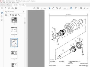
Schematics and Drawings 8-301
Figure 8-103: Lube Chart (sheet 1 of 2) 8-302
Figure 8-104: Lube Chart (sheet 2 of 2) 8-303
8-
IMAGES PREVIEW OF THE MANUAL:
More products