$38
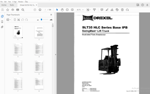
Drexel SLT35 HLC Series Base IPB SwingMast Lift Truck Parts Manual 1415693 - PDF DOWNLOAD
Drexel SLT35 HLC Series Base IPB SwingMast Lift Truck Parts Manual 1415693 - PDF DOWNLOAD
FILE DETAILS:
Drexel SLT35 HLC Series Base IPB SwingMast Lift Truck Parts Manual 1415693 - PDF DOWNLOAD
Language : English
Pages : 334
Downloadable : Yes
File Type : PDF
TABLE OF CONTENTS;
Drexel SLT35 HLC Series Base IPB SwingMast Lift Truck Parts Manual 1415693 - PDF DOWNLOAD
Contents Page
SLT-35-HLC Non-Guided Base IPB
General 8-9
Abbreviations 8-9
Phantoms / Reference Parts 8-9
Task Groups/Assemblies 8-9
Frame Position and Installation, FR24 8-12
Figure 8-1: Frame Position and Installation, FR24 8-13
Frame Bearing Installation, FR25 8-16
Figure 8-2: Frame/Shift Cylinder Bearing Installation, FR25 8-17
Drive Motor Installation, DA 12-C 8-20
Figure 8-3: Drive Motor Installation, DA12-C 8-21
Drive Unit, Dual Chain, p/n: 1400695-A - ,'8-22
Figure 8-4: Drive Unit, Dual Chain, p/n: 1400695-A 8-25
Traction Motor, Rear Drive, p/n: 1400694-A 8-26
Figure 8-5: Traction Motor, Rear Drive, p/n: 1400694-A 8-27
Steer Idler Assembly, p/n: 1412460-A 8-28
Figure 8-6: Steer Idler Assembly, p/n: 1412460-A 8-29
Drive Unit Sub-Assembly, DAB 8-32
Figure 8-7: Drive Unit Sub-Assembly, DAB 8-33
Chain Assembly for Steering, p/n: 1400109-B 8-34
Figure 8-8: Chain Assembly for Steering, p/n: 1400109-B 8-34
Drive Wheel Installation, DA2-A 8-35
Figure 8-9: Drive Wheel Installation, DA2-A 8-35
Steer Idler Installation, DA9-A 8-38
Figure 8-10: Steer Idler Installation, DA9-A 8-39
Lower Drive Unit Installation, DA 11-A 8-41
Figure 8-11: Lower Drive Unit Installation, DA11-A 8-41
Press Drive Plate Studs, DA14 8-43
Figure 8-12: Press Drive Plate Studs, DA 14 8-43
Spindle Installation, LW3-B 8-46
Figure 8-13: Spindle Installation, LW3-B 8-47
Load Wheel Installation, LW6-B 8-49
Figure 8-14: Load Wheel Installation, LW6-B 8-49
Load Wheel Sub-Assembly, LW7-A 8-51
Figure 8-15: Wheel Sub-Assembly, LW7-A 8-51
SLT35 "HLC" Series, Non-Guided Base unit, p/n: 1415693 -c, 10/03 8-3
0 Table of Contents
Contents - continued Page
Service Brake Installation, SB6 8-54
Figure 8-16: Service Brake Installation, SB6 8-55
Right and Left Brake Assembly, p/n: 51082-01 and -02 8-56
Figure 8-17: Right and Left Brake Assembly, p/n: 51802 -01 and -02 8-57
Controller Installation, EL46-A 8-59
Figure 8-18: Controllers Installation, EL46-A 8-59
Control Panel Modification, p/n: 1413417-A 8-60
Figure 8-19: Control Panel Modification, p/n: 1413417-A 8-61
Contactor Panel, p/n: 1413294-A 8-63
Figure 8-20: Contactor Panel, p/n: 1413294-A 8-63
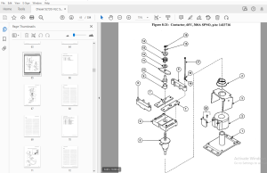
Contactor, 60V, 300A, SPNO, p/n: 1413716 8-64
Figure 8-21: Contactor, 60V, 300A SPNO, p/n: 1413716 8-65
SPNO Contactor, 80V, p/n: 1413939-A 8-66
Figure 8-22: SPNO Contactor, 80V, p/n: 1413939-A , 8-67
Wire Harness Installation, EL32 8-70
Figure 8-23: Wire Harness Installation, EL32 8-71
Battery Connector Sub-Assembly, EL21-B 8-74
Figure 8-24: Battery Connector Sub-Assembly, EL21-B 8-75
Cable Installation, EL27-B , 8-78
Figure 8-25: Cable Installation, EL27-B 8-79
Fluids, FL2-A 8-82
Figure 8-26: Fluids, FL2-A ~ 8-83
Hydraulic Pump and Motor Installation, HY30-A 8-86
Figure 8-27: Hydraulic Pump and Motor Installation, HY30-A 8-87
Hydraulic Pump and Motor Assembly, p/n: 1413611-C 8-88
Figure 8-28: Hydraulic Pump and Motor Assembly, p/n: 1413611-C 8-89
Main Hydraulic Gear Pump, p/n: 1420425-A 8-90
Pump Casappa Field Kit, p/n: 1420681-B 8-90
Figure 8-29: Main Hydraulic Gear Pump, p/n: 1420425-A 8-91
Motor Modification, p/n: 1413625-A 8-93
Figure 8-30: Motor Modification, p/n: 1413625-A 8-93
Electric Motor Breakdown, p/n: 1412771-A 8-94
Figure 8-31: Electric Motor Breakdown, p/n: 1412771-A , 8-95
Hydraulic Tank Installation, HY32 8-98
Figure 8-32: Hydraulic Tank Installation, HY32 8-99
Hydraulic Tank Sub-Assembly, HY31 8-102
Figure 8-33: Hydraulic Tank Sub-Assembly, HY31 8-103
Oil Filter Assembly, p/n: 1412142-A 8-105
Figure 8-34: Oil Filter Assembly, p/n: 1412142-A 8-105
8-4 SLT35 •HLCn Serles, Non-Guided Base unit, pin: 1415693 -c, 10/03
Table of Contents □
Contents - continued Page
Hydraulic Hose Installation, HY37 , 8-108
Figure 8-35: Hydraulic Hose Installation, HY37 8-109
Side Shift Hose, HY35 8-112
Figure 8-36: Side Shift Hose, HY35 , 8-113
Umbilical Assembly Installation, HY 41 8-116
Figure 8-37: Umbilical Assembly Installation, HY 41 8-117
Umbilical Assembly Installation, HY55-A , 8-120
Figure 8-38: Umbilical Assembly Installation, HY55-A 8-121
Umbilical Sub-Assembly, HY42 8-123
Figure 8-39: Umbilical Sub-Assembly, HY42 8-123
Manifold Assembly, p/n: 1414273-A 8-124
Figure 8-40: Manifold Assembly, p/n: 1414273-A 8-125
Umbilical Tray Installation, HY29 8-128
Figure 8-41: Umbilical Tray Installation, HY29 8-129
Pivot and Tilt Hose Installation, HY 40 8-132
Figure 8-42: Pivot and Tilt Hose Installation, HY40 8-133
Steer Pump and Motor Installation, HY11-A 8-136
Figure 8-43: Steer Pump/Motor Installation, HY11-A 8-137
Steer Pump and Motor Sub-Assembly, HY 43-A 8-139
Figure 8-44: Steer Pump anti Motor Sub-Assembly, HY43-A 8-139
Pump and Motor Assembly, p/n: 1416546-B 8-140
Figure 8-45: Pump and Motor Assembly, Steering, p/n: 1416546-B 8-141
Steering Pump, p/n: 51734 8-143
Figure 8-46: Steering Pump, p/n: 51734 8-143
Steering Motor Assembly, p/n: 51735-01 8-144
Figure 8-47: Steering Motor Assembly, p/n: 51735-01 8-145
Power Steering Hydraulic Installation, HY14-B 8-147
Figure 8-48: Power Steering Hydraulic Installation, HY14-B 8-147
Steer Motor Sub-Assembly, HY21-A 8-150
Figure 8-49: Steer Motor Sub-Assembly, HY21-A 8-151
Steering Motor Assembly, p/n: 25950-A 8-152
Figure 8-50: Steering Motor Assembly, p/n: 25950-A 8-153
Control Valve Installation, p/n: HY50-A 8-156
Hydraulic Spool Valve Assembly, p/n: 1415064-D 8-157
Figure 8-51: Hydraulic Spool Valve Assembly, p/n: 1415064-D 8-158
Side Console Sub-Assembly, HY58-A 8-162
Figure 8-52: Side Console Sub-Assembly, HY58 8-163
Joystick Hydraulic Sub-Assembly, HY24 8-165
Figure 8-53: Joystick Hydraulic Sub-Assembly, HY24 8-165
Joystick Assembly, p/n: 1406119-A and 1406120-A 8-166
Figure 8-54: Joystick Assembly 8-167
SLT35 "HLc· Series, Non-Guided Base unit, pin: 1415693 -c, 10/03 8-5
D Table of Contents
Contents - continued Page
Instruments and Side Console Installation, I □ 7-A 8-170
Figure 8-55: Instruments and Side Console Installation, I07-A 8-171
Instrument Panel Assembly, p/n: 1413726-E 8-172
Figure 8-56: Instrument Panel Assembly, p/n: 1413726-E 8-173
Side Console Installation, OH10 8-176
Figure 8-57: Side Console Installation, OH10 8-177
Steering Wheel Installation, I 04-A 8-179
Figure 8-58: Steering Wheel Installation, I04-A 8-179
Horn Button Installation, OH2-A 8-182
Figure 8-59: Horn Button Installation, OH2-A 8-183
Operator Console Installation, OH6-A 8-185
Figure 8-60: Operator Console Installation, OH6-A • 8-185
Steering Column Installation, HY5-B 8-187
Figure 8-61: Steer Column Installation, HY5-B 8-187
Steering Column Assembly, p/n: 1400968-D 8-189
Figure 8-62: Steering Column Assembly, p/n: 1400968-D 8-189
Steering Control Assembly, p/n: 25975-C 8-190
Figure 8-63: Steering Control Assembly, p/n: 25975-C 8-191
Key Switch Installation, EL 14-A 8-193
Figure 8-64: Key Switch Installation, EL 14-A 8-193
Brake Weldment Assembly, SB2-A 8-196
Figure 8-65: Brake Weldment Assembly, SB2-A 8-197
Brake Pedal Installation, SB3-B • 8-200
Figure 8-66: Brake Pedal Installation, SB3-B 8-201
Master Cylinder Installation, SB4-A 8-204
Figure 8-67: Master Cylinder Installation, SB4-A 8-205
Master Cylinder Assembly, p/n: 1402557-C 8-206
Figure 8-68: Master Cylinder Assembly, p/n: 1402557-C 8-207
Accelerator Unit Installation, EL 15-A 8-209
Figure 8-69: Accelerator Unit Installation, EL 15-A 8-209
Parking Brake Installation, PB5-C 8-212
Figure 8-70: Parking Brake Installation, PB5-C 8-213
Parking Brake Installation, PB17-C 8-216
Figure 8-71: Parking Brake Installation, PB17-C 8-217
Brake Cable Installation, PB4-B 8-220
Figure 8-72: Brake Cable Installation, PB4-B 8-221
Equalizer Installation, PB2-A 8-224
Figure 8-73: Equalizer Installation, PB2-A 8-225
Seat Belt Installation, ST1-A 8-227
Figure 8-74: Seat Belt Installation, ST1-A 8-227
8-6 SLT35 "HLC~ Serles, Non-Guided Base unit, pin: 1415693 -c, 10/03
Table of Contents D
Contents - continued Page
Seat Installation, ST2-D , , 8-230
Figure 8-75: Seat Installation, ST2-D 8-231
Seat Assembly, p/n: 1413058-A 8-232
Figure 8-76: Driver's Seat Assembly, p/n: 1413058-A 8-233
Driver's Seat Group, p/n: 1420373-A (serial# 1798 & future) 8-235
Figure 8-77: Seat Group p/n: 1420373-A , 8-235
Driver's Seat Breakdown, p/n: 1420374-A 8-236
Figure 8-78: Driver's Seat Breakdown, p/n: 1420374-A 8-237
Lower Bar Installation, PS15 8-240
Figure 8-79: Lower Bar Installation, PS15 8-241
Lower Bar Sub-Assembly, PS14 8-244
Figure 8-80: Lower Bar Sub-Assembly, PS14 8-245
Pivot and Shift Installation, PS17 8-248
Figure 8-81: Pivot and Shift Installation, PS17 8-249
Pivot & Shift Chain Anchor Installation, PS21-A 8-251
Figure 8-82: Pivot & Shift Chain Anchor Installation, PS21-A 8-251
Pivot Arm Installation, PS11 8-254
Figure 8-83: Pivot Arm Installation, PS11 8-255
Shift Cylinder Installation, PS13 8-258
Figure 8-84: Shift Cylinder Installation, PS13 8-259
Shift Cylinder Sub-Assembly, PS16 8-262
Figure 8-85: Shift Cylinder Sub-Assembly, PS16 8-263
Shift Cylinder Breakdown, p/n: 1413137-A 8-264
Figure 8-86: Shift Cylinder Breakdown, p/n: 1413137-A 8-265
Pivot Cylinder Installation, PS22 8-268
Figure 8-87: Pivot Cylinder Installation, PS22 8-269
Pivot Cylinder Assembly, p/n: 1400601-A 8-270
Figure 8-88: Pivot Cylinder Assembly, p/n: 1400601-A 8-271
Cross Head Bearings Installation, PS1-A 8-274
Figure 8-89: Cross Head Bearings Installation, PS1-A 8-275
Pivot Stop Pad Installation, PS3-B 8-278
Figure 8-90: Pivot Stop Pad Installation, PS3-B 8-279
Pivot Cylinder Installation, PS22 8-282
Figure 8-91: Pivot Cylinder Installation, PS22 8-283
Pivot Cylinder Assembly, p/n: 1400601-A 8-284
Figure 8-92: Pivot Cylinder Assembly, p/n: 1400601-A 8-285
Tilt Cylinder Installation, MA52-B 8-288
Figure 8-93: Tile Cylinder Installation, MA52-B 8-289
Tilt Cylinder Breakdown, p/n: 1422314-A 8-290
Figure 8-94: Tilt Cylinder Assembly, p/n: 1422314-A 8-291
SLT35 "HLC" Serles, Non-Guided Base unit, p/n: 1415693 -c, 10/03 8-7
D Table of Contents
Contents - continued Page
Stack Valve Cover, ID6 8-294
Figure 8-95: Stack Valve Cover, ID6 8-295
Rear Compartment Seal, ID12-A 8-298
Figure 8-96: Rear Compartment Seal, ID12-A 8-299
Battery Door Installation, OH11-A 8-301
Figure 8-97: Battery Door Installation, OH11-A 8-301
Battery Door Sub-Assembly, OH13-A 8-304
Figure 8-98: Battery Door Sub-Assembly, OH13-A 8-305
Side Cover Weldment Installation, ID13 8-308
Figure 8-99: Side Cover Weldment Installation, ID13 8-309
Console Cover Sub-Assembly, OH9-B 8-311
Figure 8-100: Console Cover Sub-Assembly, OH9-B 8-311
Rear Compartment Cover, C03-B 8-314
Figure 8-101: Rear Compartment Covers, CO3-B 8-315
Floor Plate Installation, OH3 8-317
Figure 8-102: Floor Plate Installation, OH3 8-317
Floor Plate Sub-Assembly, CO2-A 8-319
Figure 8-103: Floor Plate Sub-Assembly, CO2-A 8-319
Mast Level Indicator Installation, MA53 8-322
Figure 8-104: Mast Level Indicator Installation, MA53 8-323
Overhead Guard Installation, OH1-A 8-326
Figure 8°105: Overhead Guard Installation, OH1-A 8-327
Decals Installation, p/n: ID10-B 8-329
Figure 8-106: Decals Installation, p/n: ID10-B (sheet 1 of 2) 8-330
Figure 8-107: Decals Installation, p/n: ID10-B (sheet 2 of 2) 8-331
Schematic and Diagrams 8-333
IMAGES PREVIEW OF THE MANUAL:
More products