$40
Drexel SwingMast Lift Truck R60SL CBD Base IPB Parts Manual 1416839 – PDF DOWNLOAD
Drexel SwingMast Lift Truck R60SL CBD Base IPB Parts Manual 1416839 – PDF DOWNLOAD
FILE DETAILS:
Drexel SwingMast Lift Truck R60SL CBD Base IPB Parts Manual 1416839 – PDF DOWNLOAD
Language : English
Pages : 584
Downloadable : Yes
File Type : PDF
IMAGES PREVIEW OF THE MANUAL:
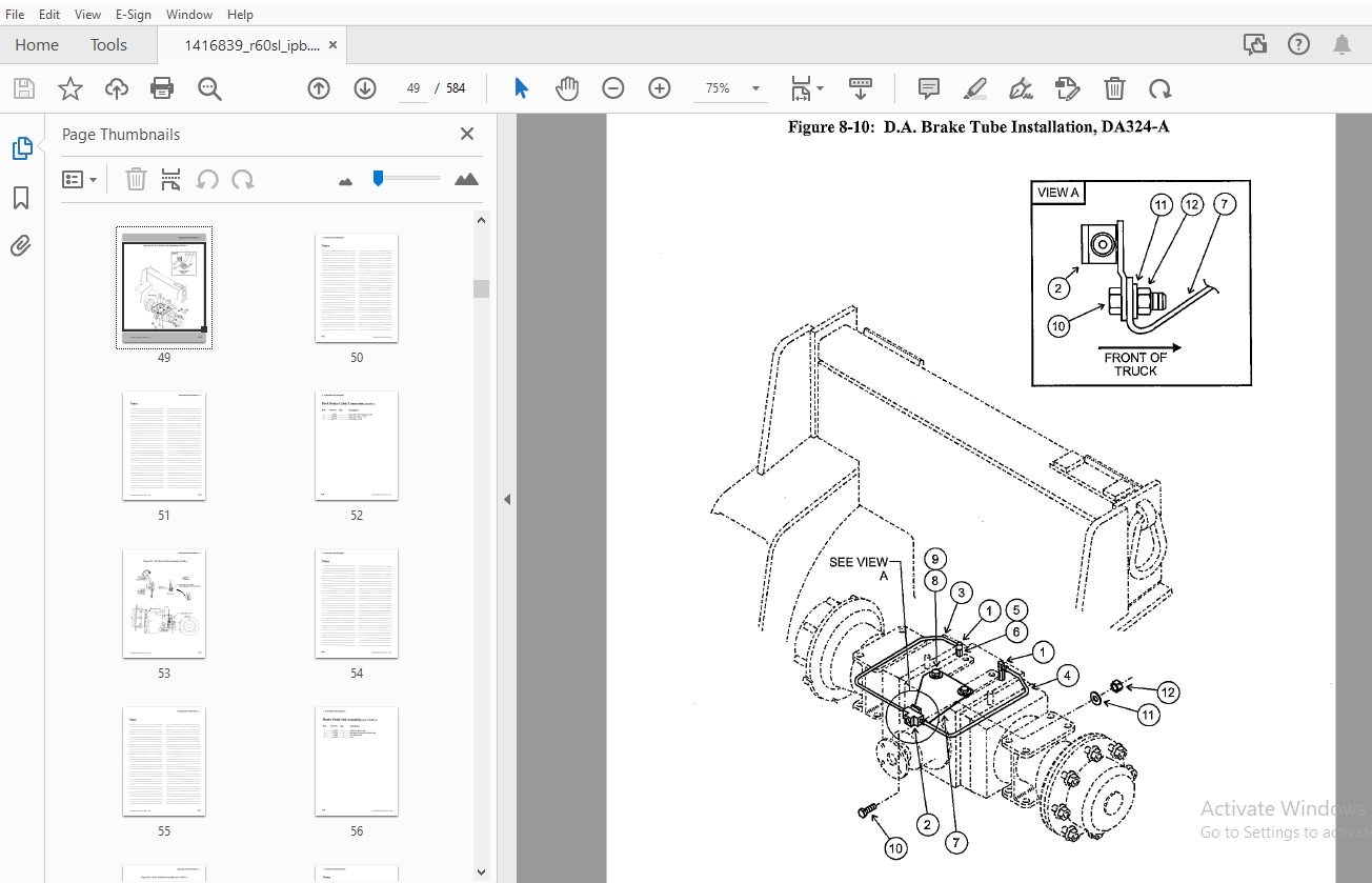
TABLE OF CONTENTS:
Drexel SwingMast Lift Truck R60SL CBD Base IPB Parts Manual 1416839 – PDF DOWNLOAD
General 8-11
Abbreviations 8-11
Phantoms / Reference Parts 8-11
Task Groups/Assemblies 8-11
Drive Axle Installation, DA326-A 8-14
Figure 8-1: Drive Axle Installation, DA326-A , 8-15
U-joint Installation, DA322 1-A 8-18
Figure 8-2: U-joint Installation, DA322 1-A 8-19
Drive Axle, Modified, DA322-A 8-22
Figure 8-3: Drive Axle, Modified, DA322-A 8-23
Disk Brake Service, p/n: 1415954-A 8-24
Figure 8-4: Disk Brake Service, p/n: 1415954-A 8-25
Differential Breakdown, p/n: 1410322-A 8-26
Differential Breakdown, p/n: 1410322-A (continued) 8-27
Figure 8-5: Differential Breakdown, p/n: 1410322-A 8-29
Axle Breakdown, p/n: 1415946-A 8-30
Axle Breakdown, p/n: 1415946-A (Continued) 8-31
Figure 8-6: Axle Breakdown, p/n: 1415946-A 8-33
Housing and Covers, Service, p/n: 1415933-A 8-34
Figure 8-7: Housing and Covers, Service, p/n: 1415933-A 8-35
Park Brake Installation, DA326 1-A 8-38
Figure 8-8: Park Brake Installation, DA326 1-A 8-39
Master Cylinder Tube Installation, DA469-A 8-42
Figure 8-9: Master Cylinder Tube Installation, DA469-A 8-43
D A Brake Tube Installation, DA324-A 8-46
Figure 8-10: D A Brake Tube Installation, DA324-A 8-47
Park Brake Cable Connection, DA481-A ! 8-50
Figure 8-11: Park Brake Cable Connection, DA481-A 8-51
Brake Pedal Sub-Assembly, p/n: CA467-A 8-54
Figure 8-12: Brake Pedal Sub-Assembly, p/n: CA467-A 8-55
Brake Linkage Installation, p/n: CA396-A 8-58
Figure 8-13: Brake Linkage Installation, p/n: CA396-A 8-59
Master Cylinder, Brake, p/n: 1407337-A 8-60
Figure 8-14: Master Cylinder, Brake, p/n: 1407337-A 8-60
Lower Cam Sub-Assembly, p/n: CA466-A 8-61
Figure 8-15: Lower Cam Sub-Assembly, p/n: CA466-A 8-61
Brake Line Installation, p/n: CA405-A 8-64
Figure 8-16: Brake Line Installation, p/n: CA405-A 8-65
Park Brake Installation, p/n: CA391-A 8-68
Figure 8-17: Park Brake Installation, p/n: CA391-A 8-69
Park Brake Switch Assembly, p/n: CA465-A 8-72
Figure 8-18: Park Brake Switch Assembly, p/n: CA465-A 8-73
Steer Axle Installation, SA478-A 8-76
Figure 8-19: Steer Axle Installation, SA478-A 8-77
Steer Axle Assembly, p/n: 1407432-D 8-78
Figure 8-20: Steer Axle Assembly, p/n: 1407432-D (sheet 1 of 2) 8-79
Figure 8-21: Steer Axle Assembly, p/n: 1407432-D {sheet 2 of 2) 8-81
Steering Cylinder, p/n: 2805184-A 8-82
Figure 8-22: Steering Cylinder, p/n: 2805184-A 8-83
Axle Oscillation Pad Installation, SA457-A 8-85
Figure 8-23: Axle Oscillation Pad Installation, SA457-A 8-85
Rear Tires and Nuts, SA361-A 8-87
Figure 8-24: Rear Tires and Nuts, SA361-A 8-87
Steering Tire and Wheel Assembly, p/n: 1400854-B 8-88
Figure 8-25: Steering Tire and Wheel Assembly, pin: 1400854-8; • 8-88
Front Tires and Nuts, DA362-A 8-90
Figure 8-26: Front Tires and Nuts, DA362-A 8-91
Drive Wheel Assembly, Inner, p/n: 1400451-A 8-92
Figure 8-27: Drive Wheel Assembly, Inner, p/n: 1400451-A • 8-92
Drive Wheel Assembly, Outer, p/n: 1400177-B 8-93
Figure 8-28: Drive Wheel Assembly, Outer, p/n: 1400177-B 8-93
Front Tires and Nuts, p/n: DA362 1-B 8-96
Figure 8-29: Front Tires and Nuts, p/n: DA362 1-B 8-97
Wheel and Tire Assembly, p/n: 1404928-A 8-98
Figure 8-30: Wheel and Tire Assembly, p/n: 1404928cA 8-98
Wheel and Tire Assembly, p/n: 1404929-A • 8-99
Figure 8-31: Wheel and Tire Assembly, p/n: 1404929-A 8-99
Drive Tire Nut Re-torque, IA192-E 8-102
Figure 8-32: Drive tire Nut Re-torque, IA192-E 8-103
Accelerator Pedal Assembly, CA476-C 8-105
Figure 8-33: Accelerator Pedal Assembly, CA476-C 8-105
Accelerator Cable Installation, CA404 1-A 8-108
Figure 8-34: Accelerator Cable Installation, CA404 1-A 8-109
Silicone Insulation Pins, CA392 1-A 8-111
Figure 8-35: Silicone Insulation Pins, CA392 1-A 8-111
Engine and Transmission Installation, ET415-A , , 8-114
Figure 8-36: Engine and Transmission Installation, ET415-A 8-115
Engine and Transmission Installation, ET341 4-A 8-118
Figure 8-37: Engine & Transmission Installation, ET341 4-A 8-119
Engine Front Cover Bolts, ET345 5-A , 8-121
Figure 8-38: Engine Front Cover Bolts, ET345 5-A 8-121
Engine & Transmission Sub-Install, p/n: ET2-A , 8-124
Figure 8-39: Engine & Transmission Sub-Installation, p/n: ET2-A 8-125
Engine Mount Installation, ET315-A 8-128
Figure 8-40: Engine Mount Installation, ET315-A 8-129
Engine Mount Sub-Assembly, ET314 1-A 8-132
Figure 8-41: Engine Mount Sub-Assembly, ET314 1-A 8-133
Engine and Transmission Mounting, ET356 1-A 8-136
Figure 8-42: Engine and Transmission Mounting, ET356 1-A 8-137
Torque Converter Installation, ET346-A , 8-140
Figure 8-43: Torque Converter Installation, ET346-A 8-141
Transmission lnstallaiton, ET3-A 8-144
Figure 8-44: Transmission lnstallaiton, ET3-A 8-145
Tandem Gear Pump Sub-Assembly, ET440-A 8-148
Figure 8-45: Tandem Gear Pump Sub-Assembly, ET440-A 8-149
Tandem Gear Pump Service Parts, p/n: 1409398-A 8-151
Figure 8-46: Tandem Gear Pump Service Parts, p/n: 1409398-A 8-151
Transmission Remote Filter, ET345 3-A 8-154
Figure 8-47: Transmission Remote Filter, ET345 3-A 8-155
Inch Bracket Installation, ET352-A 8-158
Figure 8-48: Inch Bracket Installation, ET352-A 8-159
Transmission Drain Port Line, ET450-A 8-162
Figure 8-49: Transmission Drain Port Line, ET450-A 8-163
Fuel Lines Installation, ET345 1-A 8-166
Figure 8-50: Fuel Lines Installation, ET345 1-A 8-167
Transmission Cooler Lines, ET495-A 8-170
Figure 8-51: Transmission Cooler Lines, ET495-A 8-171
Transmission Filter Lines Installation, ET474-A 8-174
Figure 8-52: Transmission Filter Lines Installation, ET 4 7 4-A 8-175
Dipstick Installation, ET353-A 8-178
Figure 8-53: Dipstick Installation, ET353-A 8-179
Air Filter Installation, Al340 1-A 8-182
Figure 8-54: Air Filter Installation, Al340 1-A 8-183
Air Guide Installation, p/n: CO458 1-A 8-186
Figure 8-55: Air Guide Installation, p/n: CO458 1-A 8-187
Blower Adapter Ring Installation, ET341 2-A 8-190
Figure 8-56: Blower Adapter Ring Installation, ET341 2-A 8-191
Blower Duct Assembly, p/n: 1407857-8 8-192
Figure 8-57: Blower Duct Assembly, p/n: 1407857-B 8-193
Cab Heater Hose Installation, p/n: ET351 2-A 8-196
Figure 8-58: Cab Heater Hose Installation, p/n: ET351 2-A 8-197
Heater Hose-to-Engine, p/n: CA407 2-A 8-199
Figure 8-59: Heater Hose-to-Engine, p/n: CA407 2-A 8-199
Heater Control Cable, p/n: CA407-A 8-201
Figure 8-60: Heater Control Cable, p/n: CA407-A 8-201
Tachometer Drive Installation, ET345 7-A 8-204
Figure 8-61 : Tachometer Drive Installation, ET345 7-A 8-205
Alternator Installation, ET 443-A • 8-208
Figure 8-62: Alternator Installation, ET443-A 8-209
Alternator Service, p/n: 1402695-B 8-210
Figure 8-63: Alternator, Service, p/n: 1402695-8 8-211
Shut-Down Solenoid, ET444-A 8-213
Figure 8-64: Shut-Down Solenoid, ET444-A 8-213
Engine Filter Lines Installation, ET345 4-A 8-216
Figure 8-65: Engine Filter Lines Installation, ET345 4-A 8-217
Throttle Linkage Installation, ET351-A 8-220
Figure 8-66: Throttle Linkage Installation, ET351-A 8-221
Lever Sub-Assembly, ET494-A 8-223
Figure 8-67: Lever Sub-Assembly, ET494-A 8-223
Fuel Drain Line Installation, ET1-A 8-226
Figure 8-68: Fuel Drain Line Installation, ET1-A 8-227
Engine Sump Drain, ET445 6-A 8-230
Figure 8-69: Engine Sump Drain, ET445 6-A 8-231
Muffler Installation, EX411-A 8-234
Figure 8-70: Muffler Installation, EX411-A 8-235
Muffler Assembly, p/n: 1408279-B 8-236
Figure 8-71: Muffler Assembly, p/n: 1408279-8 8-237
Filter Tray Installation, FT305-A 8-240
Figure 8-72: Filter Tray Installation, FT305-A 8-241
Filter Tray Sub-Assembly, FT376-A 8-244
Figure 8-73: Filter Tray Sub-Assembly, FT376-A 8-245
Engine Oil Filter Sub-Assembly, FT387-A 8-248
Figure 8-74: Engine Oil Filter Sub-Assembly, FT387-A 8-249
Transmission Filter Sub-Assembly, FT388-A 8-252
Figure 8-75: Transmission Filter Sub-Assembly, FT388-A : 8-253
Fuel Filter Sub-Assembly, FT319-A 8-255
Figure 8-76: Fuel Filter Sub-Assembly, FT319-A 8-255
Fuel and Water Separator Assembly, FT320-A 8-258
Figure 8-77: Fuel and Water Separation Assembly, FT320-A 8-259
Fuel Water Separator Breakdown, p/n: 1408265-A 8-260
Figure 8-78: Fuel Water Separator Breakdown, p/n: 1408265-A 8-261
Dash Panel Installation, CA380-A 8-264
Figure 8-79: Dash Panel Installation, CA380-A 8-265
Instrument Panel Assembly, p/n: 1411581-B 8-266
Instrument Panel Assembly, p/n:1411581-8 (continued) 8-267
Figure 8-80: Instrument Panel Assembly, Standard, p/n: 1411581-8 8-269
Console Sub-Assembly, CA389-A 8-272
Figure 8-81: Console Sub-Assembly, CA389-A 8-273
Console Installation, p/n: OH33-A 8-275
Figure 8-82: Console Installation, p/n: OH33-A 8-275
Console Assembly, p/n: 1411422-D 8-276
Figure 8-83: Console Assembly, p/n: 1411422-D 8-277
Steer Column Assembly, p/n: 1410468-F 8-278
Figure 8-84: Steer Column Assembly, p/n: 1410468-F 8-279
Lower Steering Column, Modified, p/n: 1402996- C 8-280
Figure 8-85: Lower Steering Column, Modified, p/n: 1402996- C 8-281
Switch Assembly, p/n: 1408219-8 8-282
Figure 8-86: Switch Assembly, p/n: 1408219-8 8-283
Fuse Panel, Door Assembly, p/n: 1410127-A 8-284
Figure 8-87: Fuse Panel, Door Assembly, p/n: 1410127-A 8-285
Steer Column Installation, p/n: CA422 1-A 8-288
Figure 8-88: Steer Column Installation, p/n: CA422 1-A 8-289
Steer Column Assembly, p/n: 1410468-F 8-290
Figure 8-89: Steer Column Assembly, p/n: 1410468-F 8-291
Lower Steering Column, Modified, p/n: 1402996- C 8-292
Figure 8-90: Lower Steering Column, Modified, p/n: 1402996- C 8-293
Switch Assembly, p/n: 1408219-8 8-294
Figure 8-91: Switch Assembly, p/n: 1408219-8 8-295
Fuse Panel, Door Assembly, p/n: 1410127-A 8-296
Figure 8-92: Fuse Panel, Door Assembly, p/n: 1410127-A 8-297
Steer Column Sub-Assembly, OH399 1 8-300
Figure 8-93: Steer Column Sub-Assembly, OH399 1 8-301
Wire, Wheel Installation, CA384-A 8-304
Figure 8-94: Wire, Wheel Installation, CA384-A 8-305
R60SL CBD Serles, Base assembly, pin: 1416839 -c, 08/03 8-5
Figure 8-95: Orbitrol Installation, CA403-A 8-309
Orbitrol Sub-Assembly, CA365-A 8-312
Figure 8-96: Orbitrol Sub-Assembly, CA365-A 8-313
Steering Control Unit, p/n: 1404339-B 8-314
Figure 8-97: Steering Control Unit, p/n: 1404339-B 8-315
Steering Lines Frame Installation, HY338-C 8-318
Figure 8-98: Steering Lines Frame Installation, HY338-C 8-319
Steering Lines Installation, Rear, HY339-B 8-322
Figure 8-99: Steering Lines Installation, Rear, HY339-B 8-323
Horn Installation, EL373 1-A 8-326
Figure 8-100: Horn Installation, EL373 1-A 8-327
Joystick Installation, CA402-A 8-329
Figure 8-101: Joystick Installation, CA402-A 8-329
Joystick Assembly, CA378-A 8-332
Figure 8-102: Joystick Assembly, CA378-A 8-333
Joystick Cable to Valve, CA381-A 8-336
Figure 8-103: Joystick Cable to Valve, CA381-A 8-337
Fuse Panel Door Installation, CA395 1-A 8-340
Figure 8-104: Fuse Panel Door Installation, CA395 1-A 8-341
Fuse Panel Door Assembly, p/n: 1410127-A : 8-342
Figure 8-105: Fuse Panel Door Assembly, p/n: 1410127-A 8-343
Wire Harness Installation, p/n: EL56-A 8-346
Figure 8-106: Wire Harness Installation, p/n: EL56-A 8-347
Wire Harness Routing, Front, EL373-A 8-350
Figure 8-107: Wire Harness Routing, Front, EL373-A 8-351
Wire Harness, Left Side, p/n: EL451 3-A 8-354
Figure 8-108: Wire Harness, Left Side, p/n: EL451 3-A 8-355
Fluids & Lubricants, p/n: FL331 1-A 8-358
Figure 8-109: Fluids & Lubricants, p/n: FL331 1-A 8°359
Fuel Tank Sub-Assembly, p/n: FG306-A 8-362
Figure 8-11 O: Fuel Tank Sub-Assembly, p/n: FG306-A , 8-363
Fuel Tank Installation, FG308-A 8-366
Figure 8-111: Fuel Tank Installation, FG308-A 8-367
Fuel Line Clip Installation, p/n: FG355-A 8-370
Figure 8-112: Fuel Line Clip Installation, p/n: FG355-A 8-371
Hydraulic Tank Installation, HY309-D 8-374
Figure 8-113: Hydraulic Tank Installation, HY309-D 8-375
Hydraulic Tank Assembly, p/n: 1414745-A 8-376
Figure 8-114: Hydraulic Tank Assembly, p/n: 1414745-A 8-377
Drain Lines Installation, HY318-8 8-380
Figure 8-115: Drain Lines Installation, HY318-B 8-381
Drain Plate Sub-Assembly, HY317-8 8-383
Figure 8-116: Drain Plate Sub-Assembly, HY317-8 8-383
Standard Hydraulics, HY1497-A 8-386
Figure 8-117: Standard Hydraulics, HY1497-A 8-387
Control Valve Assembly, p/n: 1416809-A 8-388
Figure 8-118: Control Valve Assembly, p/n: 1416809-A 8-389
Joystick Control, p/n: 1407330-A 8-390
Figure 8-119: Joystick Control, p/n: 1407330-A 8-391
Valve to Manifold Hose Installation, HY303-D 8-394
Figure 8-120: Valve to Manifold Hose Installation, HY303-D 8-395
Stack Valve, Installation, Low Hose, p/n: HY71-A 8-398
Figure 8-121: Stack Valve, Installation, Low Hose, p/n: HY71-A 8-399
Filter Assembly, 10 Micron, p/n: 1408618-A 8-400
Figure 8-122: Filter Assembly, 10 Micron, p/n: 1408618-A 8-400
Stack Valve Installation, HY416-B 8-402
Figure 8-123: Stack Valve Installation, HY416-B 8-403
Control Valve Assembly, p/n: 1410228-A 8-484
Figure 8-124: Control Valve Assembly, p/n: 1410228-A 8-405
Valve Spool, 4 Function, p/n: 1408724-A 8-406
Valve Spool, 4 Function, p/n: 1408724-A (Continued) 8-407
Figure 8-125: Valve Spool, 4 Function, p/n: 1408724-A 8-409
Hydraulic Hose Installation, HY325-A 8-412
Figure 8-126: Hydraulic Hose Installation, HY325-A 8-413
Hydraulic Hose Routing, HY310-A 8-416
Figure 8-127: Hydraulic Hose Routing, HY310-A 8-417
Umbilical Manifold Installation, HY368 2-C 8-420
Figure 8-128: Umbilical Manifold Installation, HY368 2-C 8-421
Umbilical Assembly, p/n: 1409002-8 8-422
Figure 8-129: Umbilical Assembly, p/n: 1409002-8 8-423
Pivot and Shift Installation, PS437-A 8-426
Figure 8-130: Pivot and Shift Installation, PS437-A 8-427
Pivot Manifold Installation, PS471-A 8-430
Figure 8-131: Pivot Manifold Installation, PS471-A 8-431
Pivot Cylinder Installation, PS426-A 8-434
Figure 8-132: Pivot Cylinder Installation, PS426-A 8-435
Pivot Cylinder Breakdown, p/n: 1407231-A 8-436
Figure 8-133: Pivot Cylinder Breakdown, p/n: 1407231-A 8-437
Pivot and Shift Hose Installation, PS436-A 8-440
Figure 8-134: Pivot and Shift Hose Installation, PS436-A 8-441
Pivot, Shift and Tilt Lines, PS442-A 8-444
Figure 8-135: Pivot, Shift and Tilt Lines, PS442-A 8-445
Tilt Cylinder Line Installation, PS473-A 8-448
Figure 8-136: Tilt Cylinder Line Installation, PS473-A 8-449
Pivot Seal Installation, PS419-A 8-452
Figure 8-137: Pivot Seal Installation, PS419-A 8-453
Mast Lines Installation, Lower, PS447-A 8-456
Figure 8-138: Mast Lines Installation, Lower, PS447-A 8-457
Roller Bearing Cup Installation, PS417 1-A 8-459
Figure 8-139: Roller Bearing Cup Installation, PS417 1-A 8-459
Radial Bushing Installation, PS417-A 8-462
Figure 8-140: Radial Bushing Installation, PS417-A 8-463
Pivot Bearing Installation, PS419 1-A 8-466
Figure 8-141: Pivot Bearing Installation, PS419 1-A 8-467
Fixed Side Shift Chain Installation, PS425-A 8-470
Figure 8-142: Fixed Side Shift Chain Installation, PS425-A 8-471
Yoke and Chain Sheave Sub-Assembly, PS428-A 8-474
Figure 8-143: Yoke and Chain Sheave Sub-Assembly, PS428-A 8-475
Side Shift Cylinder Installation, PS423-A 8-478
Figure 8-144: Side Shift Cylinder Installation, PS423-A 8-479
Shift Cylinder Breakdown, p/n: 1400006-B 8-480
Figure 8-145: Shift Cylinder Breakdown, p/n: 1400006-B 8-481
Side Shift Bearing Installation, PS432-A 8-484
Figure 8-146: Side Shift Bearing Installation, PS432-A 8-485
Crosshead Pivot Arm Installation, PS429-A 8-488
Figure 8-147: Crosshead Pivot Arm Installation, PS429-A 8-489
Bearing Assembly, PS421-A 8-492
Figure 8-148: Bearing Assembly, PS421-A 8-493
Side Shift Roller Bearing Installation, PS432 1-A 8-496
Figure 8-149: Side Shift Roller Bearing -Installation, PS432 1-A 8-497
Stop Block Installation, PS434-A 8-500
Figure 8-150: Stop Block Installation, PS434-A 8-501
Driver’s Cab Installation, CA400-A 8-504
Figure 8-151: Driver’s Cab Installation, CA400-A 8-505
Cab Modification, p/n: CA454 1-A 8-507
Cab Service Breakdown, p/n: 1410899-C 8-508
Cab Service Breakdown, p/n: 1410899-C (continued) 8-509
Figure 8-152: Cab Service Breakdown, p/n: 1410899-C 8-511
Driver’s Cab Installation, p/n: CA377 1-A 8-514
Figure 8-153: Driver’s Cab Installation, p/n: CA377 1-A 8-515
Cab Service Breakdown, p/n: 1410898-A 8-517
Cab Service Breakdown, p/n: 1410898-A (continued) 8-518
Figure 8-154: Cab Service Breakdown, p/n: 1410898-A 8-519
Driver’s Cab Sub-Assembly, p/n: CA371 1-A 8-522
Figure 8-155: Driver’s Cab Sub-Assembly, p/n: CA371 1-A 8-523
Cab to Frame Ground, p/n: EL431-A 8-525
Figure 8-156: Cab to Frame Ground, p/n: EL431-A 8-525
Battery Tray Installation, p/n: EL477 1-A 8-528
Figure 8-157: Battery Tray Installation, p/n: EL477 1-A 8-529
Battery Cables Installation, EL307 1-A 8-532
Figure 8-158: Battery Cables Installation, EL307 1-A 8-533
Rear View Mirror Installation, OH512-A 8-536
Figure 8-159: Rear View Mirror Installation, OH512-A 8-537
Brake & Tail Light, p/n: CA379-A 8-540
Figure 8-160: Brake & Tail Light, p/n: CA379-A 8-541
Lamp, Single Bulb, p/n: 28789-A 8-542
Figure 8-161: Lamp, Single Bulb, p/n: 28789-A 8-542
Lower Counterweight Installation, CT311-A 8-544
Figure 8-162: Lower Counterweight Installation, CT311-A 8-545
Side Counterweight Installation, CT335-A 8-548
Figure 8-163: Side Counterweight Installation, CT335-A 8-549
Rear Counterweight Installation, CT359 1-A 8-552
Figure 8-164: Rear Counterweight Installation, CT359 1-A 8-553
Rear Counterweight Sub-Assembly, CT337 1-A 8-556
Figure 8-165: Rear Counterweight Sub-Assembly, CT337 1-A 8-557
Rear Counterweight Sub-Assembly, p/n: CT9-A 8-560
Figure 8-166: Rear Counterweight Sub-Assembly, p/n: CT9-A 8-561
Side Cover and Hood Install, p/n: CO363 1-A 8-564
Figure 8-167: Side Cover and Hood Install, p/n: CO363 1-A 8-565
Rear Covers Installation, p/n: CO360 2-A 8-568
Figure 8-168: Rear Covers Installation, p/n: CO360 2-A 8-569
Cab Door Bumper Installation, p/n: CA456-A 8-571
Figure 8-169: Cab Door Bumper Installation, p/n: CA456-A 8-571
Standard “Yellow” Paint, PA1401-A 8-573
Identification Group, Decals, p/n: ID983 1-A 8-575
Identification Group, p/n: ID983 1-A (continued) 8-576
Figure 8-170: ID Group, p/n: ID983 1-A (sheet 1 of 2) 8-577
Figure 8-171: ID Group, p/n: ID983 1-A (sheet 2 of 2) 8-579
Schematics and Drawings 8-581
More products