$40
Drexel SwingMast Lift Truck R60SL CBD Base IPB Parts Manual 1416841 – PDF DOWNLOAD
Drexel SwingMast Lift Truck R60SL CBD Base IPB Parts Manual 1416841 – PDF DOWNLOAD
FILE DETAILS:
Drexel SwingMast Lift Truck R60SL CBD Base IPB Parts Manual 1416841 – PDF DOWNLOAD
Language : English
Pages : 558
Downloadable : Yes
File Type : PDF
IMAGES PREVIEW OF THE MANUAL:
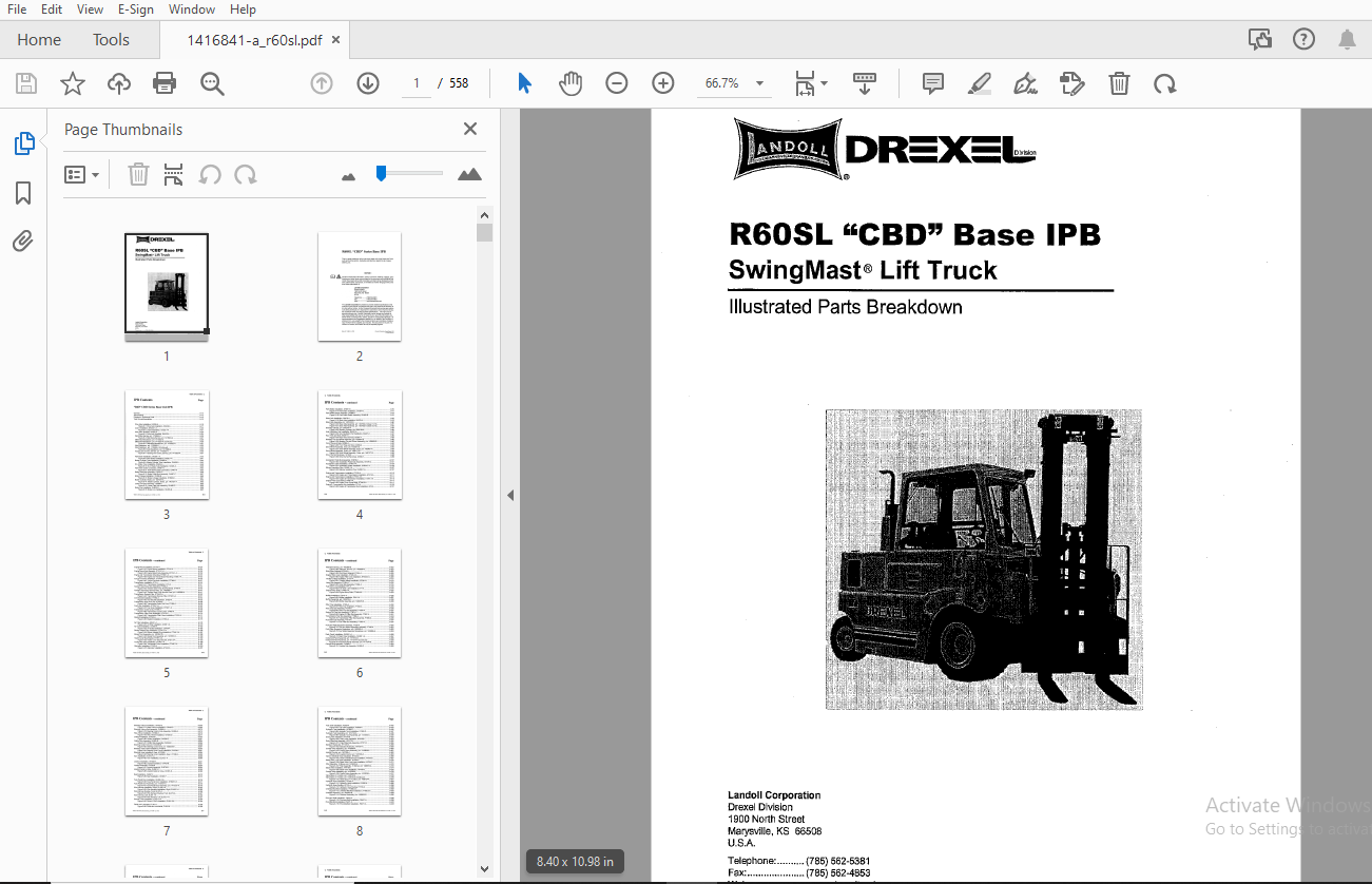
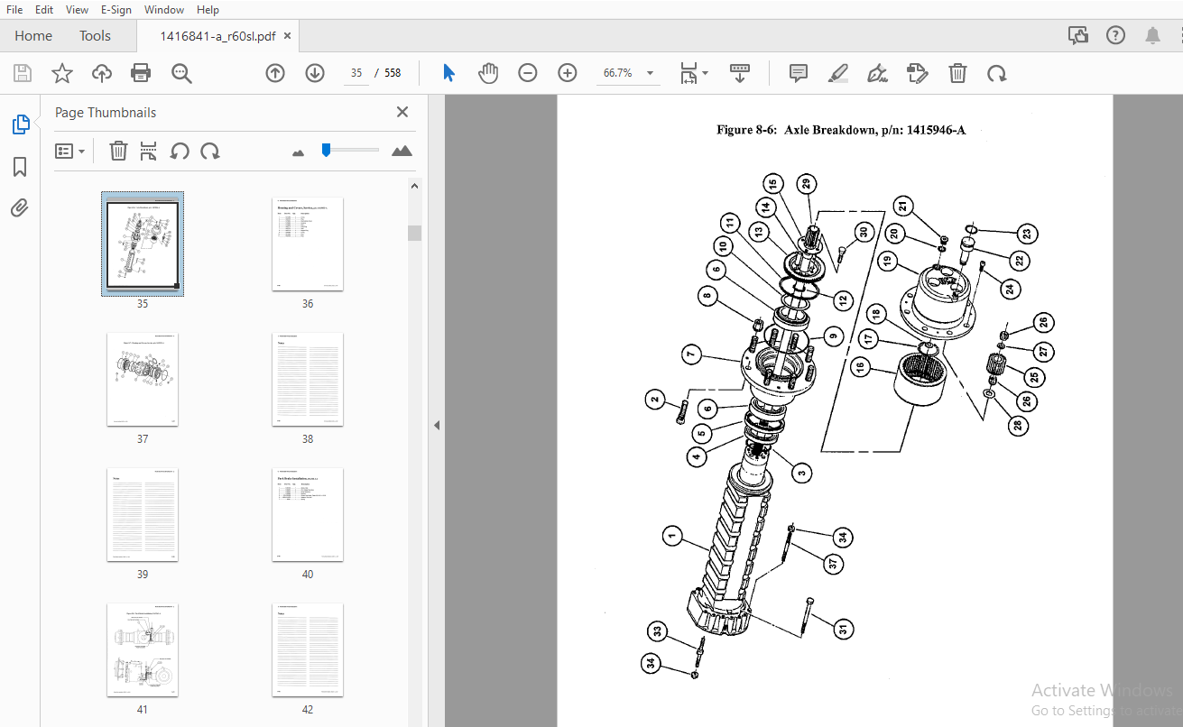
TABLE OF CONTENTS:
Drexel SwingMast Lift Truck R60SL CBD Base IPB Parts Manual 1416841 – PDF DOWNLOAD
“R60” CBD Series Base Unit IPB
General 8-13
Abbreviations 8-13
Phantoms / Reference Parts 8-13
Task Groups/Assemblies 8-13
Drive Axle Installation, DA326-A 8-16
Figure 8-1: Drive Axle Installation, DA326-A 8-17
U-joint Installation, DA322 1-A 8-20
Figure 8-2: U-joint Installation, DA322 1-A 8-21
Drive Axle, Modified, DA322-A 8-24
Figure 8-3: Drive Axle, Modified, DA322-A 8-25
Disk Brake Service, p/n: 1415954-A 8-26
Figure 8-4: Disk Brake Service, p/n: 1415954-A 8-27
Differential Breakdown, p/n: 1410322-A 8-28
Differential Breakdown, p/n: 1410322-A (continued) 8-29
Figure 8-5: Differential Breakdown, p/n: 1410322-A 8-31
Axle Breakdown, p/n: 1415946-A 8-32
Axle Breakdown, p/n: 1415946-A (Continued) 8-33
Figure 8-6: Axle Breakdown, p/n: 1415946-A 8-35
Housing and Covers, Service, p/n: 1415933-A 8-36
Figure 8-7: Housing and Covers, Service, p/n: 1415933-A 8-37
Park Brake Installation, DA326 1-A 8-40
Figure 8-8: Park Brake Installation, DA326 1-A 8-41
Master Cylinder Tube Installation, DA469-A 8-44
Figure 8-9: Master Cylinder Tube Installation, DA469-A 8-45
D A Brake Tube Installation, DA324-A 8-48
Figure 8-1 O: D A Brake Tube Installation, DA324-A 8-49
Park Brake Cable Connection, DA481-A 8-52
Figure 8-11: Park Brake Cable Connection, DA481-A 8-53
Brake Pedal Sub-Assembly, OH467-C 8-56
Figure 8-12: Brake Pedal Sub-Assembly, OH467-C 8-57
Brake Linkage Installation, OH396-B 8-60
Figure 8-13: Brake Linkage Installation, OH396-B 8-61
Master Cylinder, Brake, p/n: 1407337-A 8-62
Figure 8-14: Master Cylinder, Brake, p/n: 1407337-A 8-62
Lower Cam Sub-Assembly, OH466-C 8-63
Figure 8-15: Lower Cam Sub-Assembly, OH466-C 8-63
Brake Line Installation, OH405-B 8-66
Figure 8-16: Brake Line Installation, OH405-B 8-57
Park Brake Installation, OH391-B 8-70
Figure 8-17: Park Brake Installation, OH391-B 8-71
Park Brake Switch Assembly, OH465-B 8-74
Figure 8-18: Park Brake Switch Assembly, OH465-B 8-75
Steer Axle Installation, SA478-A 8-78
Figure 8-19: Steer Axle Installation, SA478-A 8-79
Steer Axle Assembly, p/n: 1407432-D 8-80
Figure 8-20: Steer Axle Assembly, p/n: 1407432-D (sheet 1 of 2) 8-81
Figure 8-21: Steer Axle Assembly, p/n: 1407432-D (sheet 2 of 2) 8-83
Steering Cylinder, p/n: 2805184-A 8-84
Figure 8-22: Steering Cylinder, p/n: 2805184-A 8-85
Axle Oscillation Pad Installation, SA457-A 8-87
Figure 8-23: Axle Oscillation Pad Installation, SA457-A 8-87
Rear Tires and Nuts, SA361-A 8-89
Figure 8-24: Rear Tires and Nuts, SA361-A 8-89
Steering Tire and Wheel Assembly, p/n: 1400854-B 8-90
Figure 8-25: Steering Tire and Wheel Assembly, p/n: 1400854-8 8-90
Front Tires and Nuts, DA362-A 8-92
Figure 8-26: Front Tires and Nuts, DA362-A 8-93
Drive Wheel Assembly, Inner, p/n: 1400451-A ; 8-94
Figure 8-27: Drive Wheel Assembly, Inner, p/n: 1400451-A 8-94
Drive Wheel Assembly, Outer, p/n: 1400177-B 8-95
Figure 8-28: Drive Wheel Assembly, Outer, p/n: 1400177-B 8-95
Drive Tire Nut Re-torque, IA 192-E 8-98
Figure 8-29: Drive tire Nut Re-torque, IA192-E 8-99
Accelerator Pedal Sub-Assembly, OH476-C 8-101
Figure 8-30: Accelerator Pedal Sub-Assembly, OH4 76-C 8-101
Accelerator Cable Installation, OH404 1-A 8-104
Figure 8-31: Accelerator Cable Installation, OH404 1-A 8-105
Silicone Insulation Pins, OH392 1-A 8-107
Figure 8-32: Silicone Insulation Pins, OH392 1-A 8-107
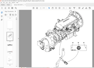
Engine and Transmission Installation, ET415-A 8-110
Figure 8-33: Engine and Transmission Installation, ET415-A 8-111
Engine and Transmission Installation, ET341 4-A 8-114
Figure 8-34: Engine & Transmission Installation, ET341 4-A 8-115
Engine Front Cover Bolts, ET345 5-A 8-117
Figure 8-35: Engine Front Cover Bolts, ET345 5-A 8-117
Engine & Transmission Sub-Installation, ET4-A 8-120
Figure 8-36: Engine & Transmission Sub Installation, ET4-A 8-121
Engine Mount Installation, ET315-A 8-124
Figure 8-37: Engine Mount Installation, ET315-A 8-125
Engine Mount Sub-Assembly, ET314 1-A • 8-128
Figure 8-38: Engine Mount Sub-Assembly, ET314 1-A 8-129
Engine and Transmission Mounting, ET356 1-A 8-132
Figure 8-39: Engine and Transmission Mounting, ET356 1-A 8-133
Torque Converter Installation, ET346-A 8-136
Figure 8-40: Torque Converter Installation, ET346-A 8-137
Transmission lnstallaiton, ET3-A 8-140
Figure 8-41: Transmission lnstallaiton, ET3-A 8-141
Tandem Gear Pump Sub-Assembly, ET440-A 8-144
Figure 8-42: Tandem Gear Pump Sub-Assembly, ET440-A 8-145
Tandem Gear Pump Service Parts, p/n: 1409398-A 8-147
Figure 8-43: Tandem Gear Pump Service Parts, p/n: 1409398-A 8-147
Transmission Remote Filter, ET345 3-A 8-150
Figure 8-44: Transmission Remote Filter, ET345 3-A 8-151
Inch Bracket Installation, ET352-A 8-154
Figure 8-45: Inch Bracket Installation, ET352-A 8-155
Transmission Drain Port Line, ET 450-A 8-158
Figure 8-46: Transmission Drain Port Line, ET450-A 8-159
Fuel Lines Installation, ET345 1-A • 8-162
Figure 8-47: Fuel Lines Installation, ET345 1-A 8-163
Transmission Cooler Lines, ET 495-A 8-166
Figure 8-48: Transmission Cooler Lines, ET495-A 8-167
Transmission Filter Lines Installation, ET474-A 8-170
Figure 8-49: Transmission Filter Lines Installation, ET 4 7 4-A 8-171
Dipstick Installation, ET353-A 8-174
Figure 8-50: Dipstick Installation, ET353-A 8-175
Air Filter Installation, Al340 1-A 8-178
Figure 8-51: Air Filter Installation, Al340 1-A 8-179
Air Guide Installation, CO458-A 8-182
Figure 8-52: Air Guide Installation, CO458-A 8-183
Blower Adapter Ring Installation, ET341 2-A 8-186
Figure 8-53: Blower Adapter Ring Installation, ET341 2-A 8-187
Blower Duct Assembly, p/n: 1407857-8 8-188
Figure 8-54: Blower Duct Assembly, p/n: 1407857-8 8-189
Heater Lever Stop Bracket, ET351 3-A 8-192
Figure 8-55: Heater Lever Stop Bracket, ET351 3-A 8-193
Tachometer Drive Installation, ET345 7-A 8-196
Figure 8-56: Tachometer Drive Installation, ET345 7-A 8-197
Alternator Installation, ET443-A 8-200
Figure 8-57: Alternator Installation, ET443-A 8-201
Alternator Service, p/n: 1402695-8 8-202
Figure 8-58: Alternator, Service, p/n: 1402695-8 8-203
Shut-Down Solenoid, ET 444-A 8-205
Figure 8-59: Shut-Down Solenoid, ET444-A 8-205
Engine Filter Lines Installation, ET345 4-A 8-208
Figure 8-60: Engine Filter Lines Installation, ET345 4-A 8-209
Throttle Linkage Installation, ET351-A 8-212
Figure 8-61: Throttle Linkage Installation, ET351-A 8-213
Lever Sub-Assembly, ET494-A 8-215
Figure 8-62: Lever Sub-Assembly, ET494-A 8-215
Fuel Drain Line Installation, ET1-A 8-218
Figure 8-63: Fuel Drain Line Installation, ET1-A 8-219
Engine Sump Drain, ET445 6-A 8-222
Figure 8-64: Engine Sump Drain, ET445 6-A 8-223
Muffler Installation, EX411-A 8-226
Figure 8-65: Muffler Installation, EX411-A 8-227
Muffler Assembly, p/n: 1408279-8 8-228
Figure 8-66: Muffler Assembly, p/n: 1408279-8 8-229
Filter Tray Installation, FT305-A 8-232
Figure 8-67: Filter Tray Installation, FT305-A 8-233
Filter Tray Sub-Assembly, FT376-A 8-236
Figure 8-68: Filter Tray Sub-Assembly, FT376-A 8-237
Engine Oil Filter Sub-Assembly, FT387-A 8-240
Figure 8-69: Engine Oil Filter Sub-Assembly, FT387-A : 8-241
Transmission Filter Sub-Assembly, FT388-A 8-244
Figure 8-70: Transmission Filter Sub-Assembly, FT388-A 8-245
Fuel Filter Sub-Assembly, FT319-A 8-247
Figure 8-71: Fuel Filter Sub-Assembly, FT319-A 8-247
Fuel and Water Separator Assembly, FT320-A 8-250
Figure 8-72: Fuel and Water Separation Assembly, FT320-A 8-251
Fuel Water Separator Breakdown, p/n: 1408265-A 8-252
Figure 8-73: Fuel Water Separator Breakdown, p/n: 1408265-A 8-253
Dash Panel Installation, OH380 1-A 8-256
Figure 8-74: Dash Panel Installation, OH380 1-A 8-257
Instrument Panel Assembly, p/n: 1411574-8 8-258
Instrument Panel Assembly, p/n: 1411574-8 (Continued) 8-259
Figure 8-75: Instrument Panel Assembly, p/n: 1411574-8 8-261
Console Sub-Assembly, OH389-C 8-264
Figure 8-76: Console Sub-Assembly, OH389-C 8-265
Steering Column Installation, OH422-D 8-268
Figure 8-77: Steer Column Installation, OH422-D 8-269
Steering Column Sub-Assembly, OH399-A 8-272
Figure 8-78: Steering Column Sub-Assembly, OH399-A 8-273
Wire, Wheel Installation, OH384-D 8-276
Figure 8-79: Wire, Wheel Installation, OH384-D 8-277
Orbitrol Installation, OH403-B 8-280
Figure 8-80: Orbitrol Installation, OH403-B 8-281
Orbitrol Sub-Assembly, OH365-B 8-284
Figure 8-81: Orbitrol Sub-Assembly, OH365-B 8-285
Steering Control Unit, p/n: 1404339-B 8-286
Figure 8-82: Steering Control Unit, p/n: 1404339-B 8-287
Steering Lines Frame Installation, HY338-C 8-290
Figure 8-83: Steering Lines Frame Installation, HY338-C 8-291
Steering Lines Installation, Rear, HY339-B 8-294
Figure 8-84: Steering Lines Installation, Rear, HY339-B 8-295
Horn Installation, EL373 1-A 8-298
Figure 8-85: Horn Installation, EL373 1-A 8-299
Joystick Installation, OH402-B 8-301
Figure 8-86: Joystick Installation, OH402-B 8-301
Joystick Assembly, OH378-B 8-304
Figure 8-87: Joystick Assembly, OH378-B 8-305
Joystick Cable to Valve, OH381-D 8-308
Figure 8-88: Joystick Cable to Valve, OH381-D 8-309
Seat Installation, OH397-F 8-312
Figure 8-89: Seat Installation, OH397-F 8-313
Fuse Panel Door Installation, OH395 1-B 8-316
Figure 8-90: Fuse Panel Door Installation, OH395 1-B 8-317
Fuse Panel Door Assembly, p/n: 1410127-A 8-318
Figure 8-91: Fuse Panel Door Assembly, p/n: 1410127-A 8-319
Wire Harness Installation, Right, EL430 1-A 8-322
Figure 8-92: Wire Harness Installation, Right, EL430 1-A 8-323
Wire Harness Routing, Front, EL373-A 8-326
Figure 8-93: Wire Harness Routing, Front, EL373-A 8-327
Wire Harness, Left, EL451 1-A 8-330
Figure 8-94: Wire Harness, Left, EL451 1-A 8-331
Ground, OHG Installation, EL431 3-A 8-334
Figure 8-95: Ground, OHG Installation, EL431 3-A 8-335
Fluids and Lubricants, FL331-A 8-338
Figure 8-96: Fluids and Lubricants, FL331-A 8-339
Fuel Tank Installation, FG308-A : 8-342
Figure 8-97: Fuel Tank Installation, FG308-A 8-343
Hydraulic Tank Installation, HY309-D 8-346
Figure 8-98: Hydraulic Tank Installation, HY309-D • • 8-347
Hydraulic Tank Assembly, p/n: 1414745-A 8-348
Figure 8-99: Hydraulic Tank Assembly, p/n: 1414745-A 8-349
Drain Lines Installation, HY318-8 8-352
Figure 8-100: Drain Lines Installation, HY318-B 8-353
Drain Plate Sub-Assembly, HY317-8 8-355
Figure 8-101: Drain Plate Sub-Assembly, HY317-B 8-355
Standard Hydraulics, HY1497-A 8-358
Figure 8-102: Standard Hydraulics, HY1497-A 8-359
Control Valve Assembly, p/n: 1416809-A 8-360
Figure 8-103: Control Valve Assembly, p/n: 1416809-A 8-361
Joystick Control, p/n: 1407330-A 8-362
Figure 8-104: Joystick Control, p/n: 1407330-A 8-363
Valve to Manifold Hose Installation, HY303-D 8-366
Figure 8-105: Valve to Manifold Hose Installation, HY303-D 8-367
Stack Valve, Low Hose Installation, HY304-C 8-370
Figure 8-106: Stack Valve, Low Hose Installation, HY304-C 8-371
Filter Assembly, 10 Micron, p/n: 1408618-A 8-372
Figure 8-107: Filter Assembly, 10 Micron, p/n: 1408618-A 8-372
Stack Valve Installation, HY416-B 8-374
Figure 8-108: Stack Valve Installation, HY 416-8 8-375
Control Valve Assembly, p/n: 1410228-A 8-376
Figure 8-109: Control Valve Assembly, p/n: 1410228-A 8-377
Valve Spool, 4 Function, p/n: 1408724-A 8-378
Valve Spool, 4 Function, p/n: 1408724-A (Continued) 8-379
Figure 8-110: Valve Spool, 4 Function, p/n: 1408724-A 8-381
Hydraulic Hose Installation, HY325-A 8-384
Figure 8-111: Hydraulic Hose Installation, HY325-A 8-385
Hydraulic Hose Routing, HY310-A 8-388
Figure 8-112: Hydraulic Hose Routing, HY310-A 8-389
Umbilical Manifold Installation, HY368 2-C 8-392
Figure 8-113: Umbilical Manifold Installation, HY368 2-C 8-393
Umbilical Assembly, p/n: 1409002-8 8-394
Figure 8-114: Umbilical Assembly, p/n: 1409002-B 8-395
Pivot and Shift Installation, PS437-A 8-398
Figure 8-115: Pivot and Shift Installation, PS437-A 8-399
Pivot Manifold Installation, PS471-A 8-402
Figure 8-116: Pivot Manifold Installation, PS471-A 8-403
Pivot Cylinder Installation, PS426-A 8-406
Figure 8-117: Pivot Cylinder Installation, PS426-A 8-407
Pivot Cylinder Breakdown, p/n: 1407231-A 8-408
Figure 8-118: Pivot Cylinder Breakdown, p/n: 1407231-A 8-409
Pivot and Shift Hose Installation, PS436-A 8-412
Figure 8-119: Pivot and Shift Hose Installation, PS436-A 8-413
Pivot, Shift and Tilt Lines, PS442-A 8-416
Figure 8-120: Pivot, Shift and Tilt Lines, PS442-A 8-417
Tilt Cylinder Line Installation, PS473-A 8-420
Figure 8-121: Tilt Cylinder Line Installation, PS473-A 8-421
Pivot Seal Installation, PS419-A 8-424
Figure 8-122: Pivot Seal Installation, PS419-A 8-425
Mast Lines Installation, Lower, PS447-A 8-428
Figure 8-123: Mast Lines Installation, Lower, PS447-A 8-429
Roller Bearing Cup Installation, PS417 1-A 8-431
Figure 8-124: Roller Bearing Cup Installation, PS417 1-A 8-431
Radial Bushing Installation, PS417-A 8-434
Figure 8-125: Radial Bushing Installation, PS417-A 8-435
Pivot Bearing Installation, PS419 1-A 8-438
Figure 8-126: Pivot Bearing Installation, PS419 1-A 8-439
Fixed Side Shift Chain Installation, PS425-A 8-442
Figure 8-127: Fixed Side Shift Chain Installation, PS425-A 8-443
Yoke and Chain Sheave Sub-Assembly, PS428-A 8-446
Figure 8-128: Yoke and Chain Sheave Sub-Assembly, PS428-A 8-447
Side Shift Cylinder Installation, PS423-A 8-450
Figure 8-129: Side Shift Cylinder Installation, PS423-A 8-451
Shift Cylinder Breakdown, p/n: 1400006-B 8-452
Figure 8-130: Shift Cylinder Breakdown, p/n: 1400006-B 8-453
Side Shift Bearing Installation, PS432-A 8-456
Figure 8-131: Side Shift Bearing Installation, PS432-A 8-457
Cross head Pivot Arm Installation, PS429-A 8-460
Figure 8-132: Crosshead Pivot Arm Installation, PS429-A 8-461
Bearing Assembly, PS421-A ; 8-464
Figure 8-133: Bearing Assembly, PS421-A 8-465
Side Shift Roller Bearing Installation, PS432 1-A 8-468
Figure 8-134: Side Shift Roller Bearing Installation, PS432 1-A 8-469
Stop Block Installation, PS434-A 8-472
Figure 8-135: Stop Block Installation, PS434-A 8-473
Overhead Guard Installation, OH377 2-A 8-475
Figure 8-136: Overhead Guard Installation OH377 2-A 8-475
Overhead Guard Installation, OH468-B 8-478
Figure 8-137: Overhead Guard Installation, OH468-B 8-479
Overhead Guard Sub-Assembly, OH487-B 8-482
Figure 8-138: Overhead Guard Sub-Assembly, OH487-B 8-483
Overhead Guard Foam Installation, OH488-A 8-486
Figure 8-139: Overhead Guard Foam Installation, OH488-A 8-487
Floor Plate Installation, OH490-A , 8-490
Figure 8-140: Floor Plate Installation, OH490-A 8-491
Access Door Installation, OH491-A 8-494
Figure 8-141: Access Door Installation, OH491-A 8-495
Fuel Sender Cover, OH489 1-A 8-498
Figure 8-142: Fuel Sender Cover, OH489 1-A 8-499
Battery Tray Installation, EL477-A 8-502
Figure 8-143: Battery Tray Installation, EL477-A 8-503
Battery Cables Installation, EL307 1-A 8-506
Figure 8-144: Battery Cables Installation, EL307 1-A 8-507
Rear View Mirror Installation, OH512-A 8-510
Figure 8-145: Rear View Mirror Installation, OH512-A 8-511
Brake and Tail Light Installation, OH379-C 8-514
Figure 8-146: Brake and Tail Light Installation, OH379-C 8-515
Lamp, Single Bulb, p/n: 28789-A 8-516
Figure 8-147: Lamp, Single Bulb, p/n: 28789-A 8-516
Lower Counterweight Installation, CT311-A 8-518
Figure 8•148: Lower Counterweight Installation, CT311-A 8-519
Side Counterweight Installation, CT335-A 8-522
Figure 8-149: Side Counterweight Installation, CT335-A 8-523
Rear Counterweight Installation, CT359 1-A 8-526
Figure 8-150: Rear Counterweight Installation, CT359 1-A 8-527
Rear Counterweight Sub-Assembly, CT337 1-A 8-530
Figure 8-151: Rear Gou nterweight Sub-Assembly, CT337 1-A 8-531
Standard Cover Installation, CO360 9-A 8-533
Figure 8-152: Standard Cover Installation, CO360 9-A 8-533
Rear Covers Installation, CO560-A 8-536
Figure 8-153: Rear Covers Installation, CO560-A 8-537
Side Cover and Hood Installation, CO363-A 8-540
Figure 8-154: Side Cover and Hood Installation, CO363-A 8-541
Identification – Decals, ID982-B 8-544
Identification – Decals, ID982-A (Continued) 8-545
Figure 8-155: Identification – Decals, ID982-A (sheet 1 of 2) 8-546
Figure 8-156: Decals, ID982-A (sheet 2 of 2) 8-547
Standard “Yellow” Paint, PA1401-A 8-549
Mast Adjustment, IA480-A 8-551
Figure 8-157: Mast Adjustment, IA480-A 8-551
Front End Adjustment, IA 179-D 8-553
Figure 8-158: Front End Adjustment, IA179-D (sheet 1 of 2) 8-554
Figure 8-159: Front End Adjustment, IA179-D (sheet 2 of 2) 8-555
Schematics and Drawings 8-557
More products