$34
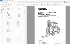
Drexel SwingMast Lift Truck SL44/4 Series Base IPB Parts Manual 1412599 - PDF DOWNLOAD
Drexel SwingMast Lift Truck SL44/4 Series Base IPB Parts Manual 1412599 - PDF DOWNLOAD
FILE DETAILS:
Drexel SwingMast Lift Truck SL44/4 Series Base IPB Parts Manual 1412599 - PDF DOWNLOAD
Language : English
Pages : 112
Downloadable : Yes
File Type : PDF
TABLE OF CONTENTS:
Drexel SwingMast Lift Truck SL44/4 Series Base IPB Parts Manual 1412599 - PDF DOWNLOAD
IPB Contents Page
General 8-1
Abbreviations 8-1
Phantoms / Reference Parts 8-1
Task Groups/Assemblies 8-1
Service Brake Group, p/n: 1412402-A 8-3
Service Brake Parts Group, p/n: 15507-E 8-5
Figure 8-1: Service Brake Parts Group, p/n: 15507-E (sheet 1 of 2) 8-6
Figure 8-2: Service Brake Parts Group, p/n: 15507-E (sheet 2 of 2) 8-7
Master Cylinder, p/n: 20210-A 8-8
Figure 8-3: Master Cylinder, p/n: 20210-A 8-9
Hand Brake Assembly, p/n: 17395 8-1 o
Figure 8-4: Hand Brake Assembly, p/n: 17395 8-1 0
Drive Assembly, p/n: 10712-10-H 8-12
Figure 8-1: Drive Assembly, p/n: 10712-10-H (sheet 1 of 2) 8-13
Figure 8-2: Drive Assembly, p/n: 10712-10-H (sheet 2 of 2) 8-14
Drive Axle with Knott Brake, p/n: 17133-8 8-15
Drive Axle with Knott Brake, p/n: 17133-S (continued} 8-16
Drive Axle with Knott Brake, p/n: 17133-S (continued) 8-17
Figure 8-3: Drive Axle with Knott Brake, p/n: 17133-S (sheet 1 of 3) 8-18
Figure 8-4: Drive Axle with Knott Brake, p/n: 17133-S (sheet 2 of 3) 8-19
Figure 8-5: Drive Axle with Knott Brake, p/n: 17133-S (sheet 3 of 3) 8-20
Cylinder Assembly, Steer, p/n: 10834-G 8-21
Figure 8-6: Cylinder Assembly, Steer, p/n: 10834-G 8-22
Steer Cylinder Assembly, p/n: 1414408 8-24
Figure 8-7: Not available at time of publication 8-24
Differential, p/n: 20230-A 8-25
Figure 8-8: Differential, p/n: 20230-A 8-26
Traction Motor, p/n: 51367-B 8-27
Figure 8-9: Traction Motor, p/n: 51367-B 8-28
Brake Assembly Modification, p/n: 30677-B 8-29
Figure 8-10: Brake Assembly Modification, p/n: 30677-B 8-30
Fluids and Grease, p/n: 30760-01 -C 8-33
Cover Group, Battery Roller & Tray, p/n: 1412285-A 8-35
Seat Group, p/n: 1412286-A 8-37
Seat Belt Assembly, Modified, p/n: 17585-B 8-38
Figure 8-1: Seat Belt Assembly, Modified, p/n: 17585-B 8-39
Electrical Group, p/n: 1412298-D 8-41
Electrical Panel Assembly, p/n: 1411564-A 8-42
Figure 8-1: Electrical Panel Assembly, p/n: 1411564-A 8-43
SL44/4 Series, Base Assembly, p/n: 1412599 a, 08/00 1
o Table of Contents
IPB Contents - continued Page
Fuse Panel Sub-Assembly, p/n: 1411604-D 8-44
Fuse Panel Sub-Assembly, p/n: 1411604-C - continued 8-45
Figure 8-2: Fuse Panel Sub-Assembly, p/n: 1411604-A (sheet 1 of 2) 8-46
Figure 8-3: Fuse Panel Sub-Assembly, p/n: 1411604-A (sheet 2 of 2) 8-4 7
Electrical Door Assembly, p/n: 15512-11-D 8-48
Electrical Door Assembly, p/n: 15512-11-D - continued 8-49
Figure 8-4: Electrical Door Assembly, p/n: 15512-11-D (sheet 1 of 2) 8-50
Figure 8-5: Electrical Door Assembly, p/n: 15512-11-D (sheet 2 of 2) 8-51
SCR Traction Control Unit, p/n: 51170-C 8-52
Figure 8-6: SCR Traction Control Unit, p/n: 51170-C 8-53
Contactor, DPDT, 300A, 36 voe Coil, p/n: 28888-D 8-54
Figure 8-7: Contactor, DPDT, 300A, 36 voe Coil, p/n: 28888-D 8-55
Contactor, 300A, 36 voe Coil, p/n: 28889-D 8-56
Figure 8-8: Contactor, 300A, 36 voe Coil, p/n: 28889-D 8-57
Battery Connector, 36 Volt, Gray, p/n: 25165-5-A 8-58
Figure 8-9: Battery Connector, 36 Volt, Gray, p/n: 25165-5-A 8-58
Capacitor Assembly, p/n: 15547-A 8-59
Figure 8-10: Capacitor Assembly, p/n: 15547-A 8-59
Foot Controller Assembly (EV-100), p/n: 17065-D 8-60
Figure 8-11: Foot Controller Assembly (EV-100), p/n: 17065-D 8-61
Seat Switch Assembly, p/n: 15659 8-62
Figure 8-12: Seat Switch Assembly, p/n: 15659 8-63
Horn Assembly, p/n: 1415796-A 8-64
Figure 8-13: Horn Assembly, p/n: 1415796-A 8-65
Tail Lamp Installation, p/n: 10902-A 8-66
Figure 8-14: Tail Lamp Installation, p/n: 10902-A 8-67
Stop and Tail Light, 36V, p/n: 25055-B 8-68
Figure 8-15: Stop and Tail Light, 36V, p/n: 25055-B 8-68
Steering Pump and Motor Assembly, p/n: 50661-06-D 8-70
Figure 8-1: Steering Pump and Motor Assembly, p/n: 50661-06-D 8-71
Pump, Power Steering, p/n: 50654-A 8-72
Figure 8-2: Pump, Power Steering, p/n: 50654-A 8-73
Motor, Power Steering, p/n: 50656-A 8-74
Figure 8-3: Motor, Power Steering, p/n: 50656-A 8-75
Steer Axle Assembly, p/n: 14221-05-F 8-77
Steer Axle Assembly, p/n: 14221-05-F (continued) 8-79
Figure 8-1: Steer Axle Assembly, p/n: 14221-05-F (sheet 1 of 2) 8-80
Figure 8-2: Steer Axle Assembly, p/n: 14221-05-F (sheet 2 of 2) 8-81
Steer Cylinder Assembly, p/n: 10834-G 8-82
Figure 8-3: Steer Cylinder Assembly, p/n: 10834-G 8-83
2 SL44/4 Series, Base Assembly, p/n: 1412599 -a, 08/00
Table of Contents D
IPB Contents - continued Page
Steer Cylinder Breakdown, p/n: 1414408-A 8-84
Figure 8-4: Steer Cylinder Breakdown, p/n: 1414408-A 8-84
Cross Head and Pivot Assembly, p/n: 17512-01-E 8-86
Figure 8-1: Cross Head and Pivot Assembly, p/n: 17512-01-E 8-87
Common Parts Group, p/n: 1412401-F 8-89
Common Parts Group, p/n: 1412401-F (continued) 8-90
Common Parts Group, p/n: 1412401-F (continued) 8-91
Figure 8-1: Common Parts Group, p/n: 1412401-F (sheet 1 of 4) 8-92
Figure 8-2: Common Parts Group, p/n: 1412401-F (sheet 2 of 4) 8-93
Figure 8-3: Common Parts Group, p/n: 1412401-F (sheet 3 of 4) 8-94
Figure 8-4: Common Parts Group, p/n: 1412401-F (sheet 4 of 4) 8-95
Knob Icons, Lift, p/n: 50382-01 8-96
Knob Icons, Tilt, p/n: 50382-02 8-96
Knob Icons, Pivot, p/n: 50382-03 8-96
Knob Icons, Shift, p/n: 50382-01 8-96
Figure 8-5: Knob Icons, p/n: 50382-01, -02, -03, -04 8-97
Door Assembly Group, p/n: 11748-05-B 8-98
Figure 8-6: Door Assembly Group, p/n: 11748-05-B 8-99
Chain Anchor Assembly, p/n: 17393-B 8-100
Figure 8-7: Chain Anchor Assembly, p/n: 17393-B 8-100
Fork and Mast Level Indicator, p/n: 36560 8-101
Figure 8-8: Fork/Mast Level Indicator, p/n: 36560 8-101
Battery Retainer Installation, p/n: 1413324-A 8-104
Figure 8-1: Battery Retainer Installation, p/n: 1413324-A 8-105
IMAGES PREVIEW OF THE MANUAL:
More products