$34
Drexel SwingMast Lift Truck SL44/4 Series Customer IPB Parts Manual 961951 - PDF DOWNLOAD
Drexel SwingMast Lift Truck SL44/4 Series Customer IPB Parts Manual 961951 - PDF DOWNLOAD
FILE DETAILS:
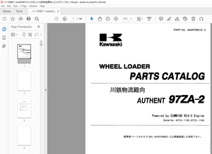
Drexel SwingMast Lift Truck SL44/4 Series Customer IPB Parts Manual 961951 - PDF DOWNLOAD
Language : English
Pages : 106
Downloadable : Yes
File Type : PDF
IMAGES PREVIEW OF THE MANUAL:

TABLE OF CONTENTS:
Drexel SwingMast Lift Truck SL44/4 Series Customer IPB Parts Manual 961951 - PDF DOWNLOAD
IPB Contents Page
General 8-107
Abbreviations 8-107
Phantoms / Reference Parts 8-107
Task Groups/Assemblies , 8-107
Operator Console Assembly, p/n: 1412398-A 8-109
Operator Console Assembly, p/n: 17372-12-B 8-11 O
Figure 8-1: Operator Console Assembly, p/n: i 7372-i 2-6 8-i ii
Cover Panel Assembly, p/n: 17371-01 8-112
Figure 8-2: Cover Panel Assembly, p/n: 17371-01 8-113
Dash Panel, Wire Harness Assembly, p/n: 1411615-A 8-114
Figure 8-3: Dash Panel, Wire Harness Assembly, p/n: 1411615-A 8-115
Instrument Panel Assembly, p/n: 17369-J 8-116
Figure 8-4: Instrument Panel Assembly, p/n: 17369-J 8-117
Lever Assembly, p/n: 10417-B 8-118
Figure 8-5: Lever Assembly, p/n: 10417-B 8-119
Orbitrol Sub-Assembly, p/n: 17430-C 8-120
Figure 8-6: Orbitrol Sub-Assembly, p/n: 17430-C 8-121
Steering Control Unit, p/n: 25715-B 8-122
Figure 8-7: Steering Control Unit, p/n: 25715-B 8-123
Steer Column with Horn, p/n: 25040-C 8-125
Figure 8-8: Steer Column with Horn, p/n: 25040-C 8-125
Steer Wheel & Horn Assembly, p/n: 1410602-A 8-126
Figure 8-9: Steer Wheel and Horn Assembly, p/n: 1410602-A 8-127
Hydraulic Assembly, p/n: 1411959-C 8-130
Hydraulic Assembly, p/n: 1411959-C (continued) 8-131
Figure 8-1 O: Hydraulic Assembly, p/n: 1411959-C (sheet 1 of 3) 8-132
Figure 8-11: Hydraulic Assembly, p/n: 1411959-C (sheet 2 of 3) 8-133
Figure 8-12: Hydraulic Assembly, p/n: 1411959-C (sheet 3 of 3) 8-135
Control Panel Assembly, p/n: 15593-08-A 8-136
Figure 8-13: Control Panel Assembly, p/n: 15593-08-A (sheet 1 of 2) 8-137
Figure 8-14: Control Panel Assembly, p/n: 15593-08-A (sheet 2 of 2) 8-139
Control Valve Assembly, p/n: 11777 8-140
Figure 8-15: Control Valve Assembly, p/n: 11777 8-141
Control Valve Modification, p/n: 50700-B 8-142
Figure 8-16: Control Valve Modification, p/n: 50700-B 8-143
Control Valve Assembly, p/n: 15592-01-A 8-144
Figure 8-17: Control Valve Assembly, p/n: 15592-01-A 8-145
Control Valve Modification, p/n: 50701-01-A 8-146
Figure 8-18: Control Valve Modification, p/n: 50701-01-A 8-147
"SL44/4~ Series, Customer order, p/n: 961951, -00, 05/00
□ Table of Contents
IPB Contents - continued Page
Pump and Motor Assembly, p/n: 14051-01-A 8-148
Figure 8-19: Pump and Motor Assembly, p/n: 14051-01-A 8-149
Motor, Pump, p/n: 21000-A ~ 8-150
Figure 8-20: Motor, Pump, p/n: 21000-A 8-151
Pump, Double Vane, 13gpm/5gpm, p/n: 21150-A 8-152
Figure 8-21: Pump, Double Vane, 13gpm/5gpm, p/n: 21150-A 8-153
Hose Kit, p/n: 1413454-A 8-154
Hose Kit, p/n: 1413455-C 8-155
Reservoir Assembly, p/n: 10845-02-K 8-156
Figure 8-22: Reservoir Assembly, p/n: 10845-02-K 8-157
Filter Assembly, Hydraulic, p/n: 17397-B, 8-158
Figure 8-23: Filter Assembly, Hydraulic, p/n: 17397-B 8-159
Shift Cylinder Assembly, p/n: 17394-01-B 8-160
Figure 8-24: Shift Cylinder Assembly, p/n: 17394-01-B , 8-161
Shift CylinderBreakdown, p/n: 51398-01-D 8-162
Figure 8-25: Shift Cylinder Breakdown, p/n: 51398-01-D 8-163
Umbilical Assembly, p/n: 1411667-A 8-164
Figure 8-26: Umbilical Assembly, p/n: 1411667-A 8-165
Pivot Cylinder, p/n: 30071-A 8-166
Figure 8-27: Pivot Cylinder, p/n: 30071-A 8-167
Tilt Cylinder, p/n: 30340-02-B 8-168
Figure 8-28: Tilt Cylinder, p/n: 30340-02-B 8-169
Interlock Group, Quad 8000, p/n: 1414612-A 8-171
Parts Group, Hydraulic, p/n: 1412304-C 8-172
Figure 8-29: Parts Group, Hydraulic, p/n: 1412304-C 8-173
Switch Group, p/n: 1414614-A 8-174
Lift Limit Switch Modification, p/n: 1414607-A 8-176
Figure 8-30: Lift Limit Switch Modification, p/n: 1414607-A 8-177
Side Shift Switch Modification, p/n: 17365-01-B 8-178
Figure 8-31: Side Shift Switch Modification, p/n: 17365-01-B 8-179
Pivot Switch Installation, p/n: 1412314-B 8-180
Figure 8-32: Pivot Switch Installation, p/n: 1412314-B 8-181
Pivot Pin and 15° Cam, p/n: 1413189-A 8-182
Figure 8-33: Pin Pivot & 15° Cam, p/n: 1413189-A 8-182
Overhead Guard Weldment, p/n: 10799-01-B 8-183
Figure 8-34: Overhead Guard Weldment, p/n: 10799-01-B 8-183
Flood Lights, OHG Mounting, p/n: 1412941-A 8-186
Figure 8-35: Flood Lights, OHG Mounting, p/n: 1412941-A 8-187
ii "SL44/4~ Series, Customer order, p/n: 961951, -00, 05/00
Table of Contents D
IPB Contents - continued Page
Flood Light Beam, 36 volts, p/n: 1412924-A 8-188
Strobe Light, Amber, p/n: 1412945-C 8-190
Figure 8-36: Strobe Light, Amber, OHG Mount, p/n: 1412945-C 8-191
Strobe Light, Amber, p/n: 1413815-A 8-192
Figure 8-37: Strobe Light, Amber, p/n: 1413815-A 8-193
Back-Up Alarm Assembly, p/n: 17318-02-C 8-195
Figure 8-38: Back-Up Alarm Assembly, p/n: 17318-02-2C 8-195
Capacitor Assembly, p/n: 15547-B 8-196
Figure 8-39: Capacitor Assembly, p/n: 15547-B 8-196
Fire Extinguisher, p/n: 50102 8-198
Figure 4-40: Fire Extinguisher, p/n: 50102 8-199
Drexel Label and Marking Group, p/n: 17559-01-D 8-201
Figure 8-41: Drexel Label and Marking Group, p/n: 17559°01-D , 8-203
Paint 8-205
Paint, Yellow Enamel, p/n: 37260-04-A 8-205
S.S 05/24
More products