$39
DREXEL SwingMast Lift Truck SLT22 & SLT30 Operation & Maintenance Manual 1404706 - PDF DOWNLOAD
DREXEL SwingMast Lift Truck SLT22 & SLT30 Operation & Maintenance Manual 1404706 - PDF DOWNLOAD
FILE DETAILS:
DREXEL SwingMast Lift Truck SLT22 & SLT30 Operation & Maintenance Manual 1404706 - PDF DOWNLOAD
Language : English
Pages : 433
Downloadable : Yes
File Type : PDF
IMAGES PREVIEW OF THE MANUAL:
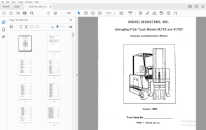
TABLE OF CONTENTS:
DREXEL SwingMast Lift Truck SLT22 & SLT30 Operation & Maintenance Manual 1404706 - PDF DOWNLOAD
Table of Contents
Section 1 DESCRIPTION AND SPECIFICATIONS
11 INTRODUCTION 1-1
12 OPERATION 1-1
13 FUNCTIONAL DESCRIPTION 1-3
131 Electrical Subsystem 1-3
132 Hydraulic Subsystem 1-3
133 Mechanical Subsystem 1-4
14 LIMITED WARRANTY 1-4
141 Warranty Policy 1-4
142 Notification 1-5
15 STORAGE 1-5
15 1 Storage of Trucks 1-5
15 :i Storage of Batteries 1-5
16 WARNINGS AND CAUTIONS 1-5
161 Warnings 1-5
162 Cautions 1-5
17 OPERATING PRECAUTIONS 1-5
18 SERVICING PRECAUTIONS 1-7
19 BATTERY MAINTENANCE PRECAUTIONS 1-8
Section 2 PREPARATION FOR USE
21 RECENING INSPECTION 2-1
22 PREPARATION FOR USE 2-1
23 CHARGING BATTERIES 2-1
24 PREPARING DRY-CHARGE BATTERIES 2-2
25 OPERTIONAL CHECKS 2-2
26 PROGRAMMING THE SCR CONTROLLER 2-4
27 OPERATION 2-4
28 DESCRIPTION OF FUNCTIONS 2-5
Section 3 OPERATION
31 OVERVIEW 3-1
32 SAFETY SUMMARY 3-1
3 21 Before Operating 3-1
322 Using Dock Boards 3-1
3 23 Moving a Load : 3-1
33 PRE-OPERATION CHECKLIST 3-2
34 OPERATING CONTROLS 3-2
35 OPERATING LIMITATIONS 3-4
36 ADJUSTING THE SEAT : 3-4
37 RUNNING FORWARD AND BACKWARD 3-5
38 MANEUVERING THE MAST 3-5
39 FORK ADJUSTMENT 3-6
310 PICKING UP A LOAD 3-6
311 DEPOSITING A LOAD 3-7
i
Table of Contents
Section 4 PRINCIPLES OF OPERATION
41 GENERAL 4-1
42 HYDRAULIC SYSTEM 4-1
421 Steering System 4-1
422 Mast Systems 4-1
423 Pivot-Tilt System 4-1
424 Lift-Shift System 4-2
43 ELECTRICAL CONTROL SYSTEM 4-2
431 General 4-2
432 Operation of the SCR Circuit 4-2
433 Plugging 4-3
434 Accelerator Operation 4-3
435 Power Bypass 4-3
436 Direction Control 4-3
43 7 Interlocks 4-3
Section 5 PREVENTIVE MAINTENANCE
51 OVERVIEW 5-1
52 DAILY CHECKS AND INSPECTIONS 5-3
521 Check Batteries 5-3
522 Check Power Steering 5-3
523 Check Pump Contactor Delay 5-3
524 Check Return-To-Neutral 5-3
525 Daily Lift Chain Inspection 5-4
526 Inspect Tires 5-4
53 WEEKLY CHECKS 5-4
5 3 1 Check Hydraulic Oil Level 5-4
532 Check Master Cylinder Fluid Level 5-4
533 Check Pivot Alignment 5-4
5 3 4 Check Tilt Alignment 5-4
54 SIX-WEEK CHECKS • 5-4
5 41 Lubricate Truck 5-4
542 Check Lift Operation ; 5-5
55 TWELVE-WEEK CHECKS • 5-5
551 Check Bolts 5-5
5 5 ,2 Change Hydraulic Oil Filter 5-5
56 SEMI-ANNUAL CHECKS 5-5
561 Adjust Lift Chain · 5-5
562 Adjust Shift Chain 5-8
5 63 Inspect Electrical Connections 5-8
564 Fork Inspection 5-8
5 6 5 Inspect Lift Chain 5-9
566 Hydraulic Pump Motor Brush Replacement 5-10
5 6 7 Power Steering Motor Brush Replacement 5-10
568 Traction Motor Brush Replacement 5-11
57 ANNUAL CHECKS 5-11
5 7 1 Change Hydraulic Oil 5-11
5 72 Change Reservoir Sump Filter 5-12
ii
Table of Contents
573 Lubricate Front Wheel Bearings 5-12
Section 6 TROUBLESHOOTING
61 GENERAL 6-1
62 PRELIMINARY PROCEDURES 6-1
63 VISIBLE PROBLEMS 6-1
631 Cracks in Forks 6-1
632 Leaking Fluid 6-1
633 Fluid Puddled Near Drive Wheel 6-1
634 Fluid Puddled Near Front Wheels 6-1
635 Fluid Puddled Near Mast 6-1
636 Frayed or Broken Wires - • 6-2
637 Lights Inoperative 6-2
638 Loose Electrical Connections 6-2
639 Scraped Rails on Mast 6-2
64 AUDIBLE PROBLEMS 6-2
64 J Backup Alarm Inoperative 6-2
642 Grinding noise when truck moves · 6-2
643 High RPM in Drive Motor 6-2
644 Horn Inoperative 6-2
645 Main Pump Runs Continuously 6-2
646 Rubbing Noise at Front Wheels 6-2
64 7 Scraping Noise When Mast is Lifted 6-2
648 SCR Unit Does Not Hurn 6-2
65 OPERATIONAL PROBLEMS 6-3
651 Brakes Do Not Stop the Truck 6-3
652 Hydraulic Functions Do Not Shut Off 6-3
653 Mast Does Not Lift 6-3
654 Mast Does Not Pivot 6-3
655 Mast Does Not Shift 6-3
656 Mast Does Not Tilt 6-4
657 Mast Drifts Downward 6-4
658 Mast Lifts Slowly 6-4
659 Parking Brake Does Not Hold the Truck 6-4
6510 Power Steering Motor Does Not Start • 6-4
65 11 Steering Drifts or is Erratic 6-4
6512 Truck Does Not Move 6-4
6513 Truck Does Not Turn 6-5
6513 Truck Moves Slowly , 6-5
65 14 Truck Turns Slowly 6-5
66 DIAGNOSTIC CODES 6-5
Section 7 CORRECTIVE MAINTENANCE
71 GENERAL 7-1
72 ADJUSTMENTS 7-1
72J IA Contactor Timing Adjustment 7-1
722 Brake Adjustment 7-1
iii
Table of Contents
723 Brake Pedal Adjustment 7-1
7 24 Main Pump Relief Valve Adjustment 7-2
725 Parking Brake Adjustment 7-3
726 Stack Valve Switch Adjustment 7-3
727 Steering Pump Relief Valve Adjustment , 7-3
728 Brake System Bleeding 7-4
7 29 Lift Cylinder Bleeding 7-5
7210 Brake Shoe Cleaning 7-5
7211 Commutator Cleaning 7-5
73 REMOVAL PROCEDURES 7-5
731 Brake Master Cylinder Removal 7-5
732 Contactor Removal 7-5
7 33 Drive Unit Removal 7-5
734 Main Pump and Motor Removal 7-6
735 Mast Removal 7-6
7 36 Pivot Cylinder Removal 7-7
737 SCR Logic Card Removal , 7-7
738 Shift Cylinder Removal 7-8
739 Steering Head Removal 7-8
7310 Steering Pump and Motor Removal 7-9
7 311 Tilt Cylinder Removal , 7-9
7312 Traction Motor Removal 7-9
74 INSTALLATION PROCEDURES 7-10
7 4 1 Brake Master Cylinder Installation 7-10
742 Contactor Installation 7-10
743 Drive Unit Installation 7-10
744 Main Pump and Motor Installation 7-10
745 Mast Installation , 7-10
746 Pivot Cylinder Installation 7-10
747 SCR Logic Card Installation , 7-10
748 Shift Cylinder Installation 7-10
74 9 Steering Head Installation 7-10
7410 Steering Pump and Motor Installation · · · :· ·, ,: 7-10
7411 Tilt Cylinder Installation 7-10
74 12 Traction Motor Installation 7-10
75 DISASSEMBLY PROCEDURES 7-10
751 Brake Master Cylinder Disassembly 7-10
752 Contactor Disassembly 7-11
753 Drive Unit Disassembly 7-11
754 Lift Cylinder Disassembly 7-11
755 Main Pump Disassembly 7-12
756 Mast Disassembly 7-13
757 Steering Head Disassembly 7-13
758 Steering Motor Disassembly 7-14
759 Steering Pump Disassembly 7-16
7510 Tilt Cylinder Disassembly 7-17
76 ASSEMBLY PROCEDURES , 7-17
761 Brake Master Cylinder Assembly 7-17
762 Contactor Assembly 7-17
763 Drive Unit Assembly 7-17
764 Lift Cylinder Assembly 7-18
iv
Table of Contents
765 Main Pump Assembly • 7-19
7 66 Mast Assembly 7-19
767 Steering Head Assembly 7-19
768 Steering Motor Assembly 7-20
769 Steering Pump Assembly 7-23
7610 Tilt Cylinder Assembly 7-23
77 REPLACEMENT PROCEDURES 7-23
7 7 1 Accelerator Assembly Replacement 7-23
772 Brake Line Replacement 7-24
773 Brake Assembly Replacement 7-24
774 Brake Switch Replacement 7-24
775 Control Fuse Replacement 7-24
776 Bulb Replacement 7-25
777 Centering Spring Replacement (Valve Stack) 7-25
7 7 8 Directional Control Switch Replacement 7-25
7 7 9 Drive Wheel Replacement 7-25
7710 Emergency Stop Switch Replacement 7-26
7 7 11 Fork Replacement 7-26
7 7 12 Front Wheel Replacement 7-26
7713 Hash Filter Replacement 7-27
7714 Horn Assembly Replacement 7-27
7 7 15 Horn Hash Filter Replacement 7-27
7716 Hydraulic Fitting Replacement 7-27
7717 Hydraulic Hose Replacement 7-28
7 7 18 Key Switch Replacement 7-28
7719 Power Fuse Replacement '· 7-28
7720 Relief Valve Replacement : 7-28
7 7 21 Rocker Switch Replacement 7-28
7 7 22 Seat Switch Replacement • 7-29
7 7 23 Wheel Cylinder Replacement ' 7-29
7724 Valve Stack Replacement · 7-29
Section 8 PARTS LIST
81 GENERAL 8-1
82 WELDMENTS 8-1
83 CONSUMABLES 8-1
831 Fuses 8-1
832 Filters 8-1
833 Motor Brushes 8-1
84 PART NUMBERS AND DESCRIPTIONS 8-2
85 INDEX TO PART NUMBERS 8-24
Section 9 ILLUSTRATED PARTS BREAKDOWN
Base Unit, Part No 1404705 RevB 9-5
Drive Group, Part No 1400628 RevF 9-6
Drive Motor, Part No 1400694 RevA 9-8
Idler Assembly, Part No 1401239 RevB 9-10
V
Table of Contents
Drive Assembly, Part No 1400645 RevD 9-12
Chain Assembly, Part No 1400109 RevB 9-14
Drive Unit, Part No 1400695 RevA 9-15
Hydraulic Group, Part No 1400629 RevR 9-19
Hydraulic Valve Assembly, Part No 1400642 RevG • 9-22
Stack Valve, Part No 1400270 RevA : 9-24
Main Pump & Motor Assembly, Part No 1400643 RevD 9-29
Main Pump, Part No 1400269 RevA 9-30
Main Pump, Electric Motor, Part No 1400268 RevA 9-32
Steer Pump & Motor Assembly, Part No 37506 RevB 9-34
Steering Pump Electric Motor, Part No 51735 RevB 9-36
Hydraulic Steering Pump, Part No 51734 RevA 9-39
Power Steering Hydraulic Assembly, Part No 1400649 RevC 9-40
Steering Motor, Part No 25950 RevA 9-42
Hydraulic Reservoir Assembly, Part No 1400258 RevE 9-44
Oil Filter Assembly, Part No 1400646 RevD 9-47
Truck Manifold Assembly, Part No 1400295 RevB 9-48
Assembly, Manifold, Part No 1402869 RevB 9-50
Operator Console Group, Part No 1400632 RevR 9-52
Instrument Panel Assembly, Part No 1400651 RevE 9-58
Console Cover Assembly, Part No 1401860 RevA 9-60
Side Console Assembly, Part No 1400931 RevF 9-62
Joystick Assemblies, Part Nos 1406119 & 1406120 9-64
Console Panel Assembly, Part No 1400498 RevD 9-66
Service Brake Components, Part No 1400648 RevH 9-68
Cylinder, Master, Part No 20210 9-70
Steering Components, Part No 1400650 RevG 9-72
Steering Control Unit, Part No 25975 Rev A 9-74
Steering Colwnn, 10", Part No 1400968 Rev A 9-77
Electrical Components, Part No 1401464 RevE 9-78
Final Assembly, Group Part No 1405733 RevB 9-80
Fluids Group, Part No 1400640 9-83
Rear Compartment Group, Part No 1401777 RevF 9-84
Panel, Contactor w/o Box, Part No 1405740 RevA 9-91
Battery Connector Subassembly, Part No 1401475 RevC • 9-94
Contactor, Main Pump Spno, 300a, Part No 28889 Rev D 9-96
Contactor, 300a, Spno 24v, Part No 1401979 RevA 9-100
Steering Pump Contactor Ah, 100a, Spno, Part No 1401980 RevA 9-102
"LX" Ser Control Panel, Part No 52511 RevA 9-104
Wiring Diagram Part No 1404780 9-106
Parking Brake Group Part No 1400633 RevH 9-110
Parking Brake Cables Part No 1400696/1400697 9-113
vi
List of IDustrations
Figure 1-1 Fork Lift Truck Operational Modes 1-1
Figure 2-1 Handset and Location of Connections on SCR 2-4
Figure 3-1 Location of Operating Controls 3-3
Figure 3-2 Location of Seat Adjustment Controls 3-4
Figure 3-3 Unlatching the Fork • 3-6
Figure 3-4 Fork Latch in Secured Position 3-7
Figure 3-5 Aligning the Truck to the Rack 3-8
Figure 3-6 Shifting and Pivoting a Load in or Out of the Rack 3-8
Figure 3-7 Inserting or Withdrawing a Load Using Shift 3-9
Figure 4-1 Power Steering System Fluid Flow 4-4
Figure 4-2 Power Steering System, Simplified Diagram 4-4
Figure 4-3 Main Pump, Simplified Diagram 4-5
Figure 4-4 Pivotffilt System, Simplified Diagram 4-5
Figure 4-5 Tilt System Anti-Cavitation Circuit , 4-6
Figure 4-6 Lift System, Simplified Diagram 4-6
Figure 4-7 Shift System, Simplied Diagram 4-7
Figure 4-8 Motor Control Circuit, Simplified Schematic 4-7
Figure 4-9 Forward and Reverse Contactor Circuit, Simplified Schematic 4-8
Figure 4-10 Electrical Interlocks, Simplified Schematic 4-8
Figure 5-1 Truck Lubrication Points ·:: 5-7
Figure 5-2 Measuring Fork Wear 5-10
Figure 5-3 Measuring Fork Distortion · 5-10
Figure 5-4 Maximum Chain Elongation 5-10
Figure 5-5 Brush Rigging 5-11
Figure 6-1 Electrical Schematic 6-7
Figure 6-2 Electrical Wiring Diagram 6-9
Figure 6-3 Hydraulic Schematic 6-11
Figure 7-1 Brake Pedal Adjustment 7-2
Figure 7-2 Valve Stack, Location of Gauge Connections 7-4
Figure 7-3 Suggested Support Fixture and Cradle 7-6
Figure 7-4 Mast Lifting 7-7
Figure 7-5 Blocking the Mast 7-7
Figure 7-6 SCR Logic Card Retaining Screws 7-8
Figure 7-7 Steering Head Hydraulic Lines 7-9
Figure 7-8 Lifting the Drive Motor 7-10
Figure 7-9 Retaining Ring Removal 7-13
Figure 7-10 Gland Bushing Removal 7-13
Figure 7-11 Centering Spring Removal 7-14
Figure 7-12 Removing Check Valve from Steering Head 7-14
Figure 7-13 Clamping Motor to Detach End Cap 7-15
Figure 7-14 Clamping Motor to Detach Flange 7-15
Figure 7-15 Prying Seals Out of Flange 7-16
Figure 7-16 Contact Pattern on Bevel Gear 7-18
Figure 7-17 Installing Centering Springs 7-20
Figure 7-18 Installing Drive Bearing 7-20
Figure 7-19 Installing Steering Head Drive 7-21
Figure 7-20 Installing Drive Spacers • 7-21
Figure 7-21 Tightening Order for End Cap Bolts 7-21
Figure 7-22 Breaking Sharp Corners of Seal Seat 7-22
Figure 7-23 Installing Flange Seal 7-22
Figure 7-24 Alignment of Timing Dot 7-23
Figure 7-25 Brake Assembly Replacement 7-24
Figure 7-26 Centering Spring in Valve Body 7-25
Figure 7-27 Removing the Directional Control Switch 7-26
List of Tables
Table 1-1 General Specifications 1-2
Table 1-2 Dimensions of Standard Triplex Masts for SLT22 and SLT30 Trucks 1-3
Table 2-1 Specific Gravity Corrections for Electrolyte Temperature 2-3
Table 2-2 Recommended Parameters for SCR Controller 2-7
Table 5-1 Preventive Maintenance Schedule 5-3
Table 5-2 Recommended Lubricants 5-8
Table 5-3 Acceptable Y Distances (inches) 5-9
S.S 05/24

