$34
Drexel SwingMast Lift Truck SLT22-EE & SLT30-EE Operation & Maintenance Manual 1404705 -
Drexel SwingMast Lift Truck SLT22-EE & SLT30-EE Operation & Maintenance Manual 1404705 - PDF DOWNLOAD
FILE DETAILS:
Drexel SwingMast Lift Truck SLT22-EE & SLT30-EE Operation & Maintenance Manual 1404705 - PDF DOWNLOAD
Language : English
Pages : 134
Downloadable : Yes
File Type : PDF
Table of Contents:
Drexel SwingMast Lift Truck SLT22-EE & SLT30-EE Operation & Maintenance Manual 1404705 - PDF DOWNLOAD
Table of Contents
Chapter I DES_CRIPTION AND SPECIFICATIONS 1-1
11 INTRODUCTION 1-1
12 OPERATION 1-1
13 FUNCTIONAL DESCRIPTION 1-2
13 1 Electrical Subsystem 1-2
132 Hydraulic Subsystem 1-2
133 Mechanical Subsystem 1-2
14 LIMITED WARRANTY 1-4
141 Warranty Policy : 1-4
142 Notification 1-4
15 STORAGE 1-5
151 Storage of Trucks 1-5
152 Storage of Batteries 1-5
16 WARNINGS AND CAUTIONS 1-5
161 Warnings 1-5
162 Cautions 1-5
17 OPERATING PRECAUTIONS 1-5
18 SERVICING PRECAUTIONS 1-7
19 BATTERY MAINTENANCE PRECAUTIONS 1-8
Chapter II PREPARATION FOR USE 2-1
21 RECEMNG INSPECTION 2-1
22 PREPARATION FOR USE 2-1
23 CHARGING BATTERIES 2-1
24 PREPARING DRY-CHARGE BATTERIES 2-2
25 OPERATIONAL CHECKS 2-2
26 PROGRAMMING THE SCR CONTROLLER 2-4
27 OPERATION 2-4
28 DESCRIPTION OF FUNCTIONS 2-5
Chapter III OPERATION 3-1
31 OVERVIEW 3-1
32 SAFETY SUMMARY 3-1
3 2 1 Before Operating 3-1
322 Using Dock Boards 3-1
323 Moving a Load 3-1
33 PRE-OPERATION CHECKLIST 3-2
34 OPERATING CONTROLS 3-2
35 OPERATING LIMITATIONS 3-4
36 ADJUSTING THE SEAT 3-4
37 RUNNING FORWARD AND BACKWARD 3-5
i
38 MANEUVERING THE MAST 3-5
39 FORK ADJUSTMENT 3-6
310 PICKING UP A LOAD 3-6
311 DEPOSITING A LOAD 3-7
Chapter IV PRINCIPLES OF OPERATION 4-1
41 GENERAL 4-1
42 HYDRAULIC SYSTEM 4-1
421 Steering System 4-1
422 Mast Systems 4-1
423 Pivot-Tilt System 4-1
424 Lift-Shift System 4-2
43 ELECTRICAL CONTROL SYSTEM 4-2
431 General 4-2
432 Operation of the SCR Circuit 4-2
433 Plugging 4-3
434 Accelerator Operation 4-3
435 Power Bypass 4-3
436 Direction Control 4-3
437 Interlocks 4-3
Chapter V PREVENTIVE MAINTENANCE 5-2
51 OVERVIEW 5-2
52 DAILY CHECKS AND INSPECTIONS 5-4
5 21 Check Batteries 5-4
522 Check Power Steering 5-4
523 Check Pump Contactor Delay 5-4
524 Check Return-to-Neutral 5-4
525 Daily Lift Chain Inspection 5-5
526 Inspect Tires 5-5
53 WEEKLY CHECKS 5-5
531 Check Hydraulic Oil Level 5-5
5 3 2 Check Master Cylinder Fluid Level 5-5
5 3 3 Check Pivot Alignment 5-5
534 Check Tilt Alignment 5-5
54 SIX-WEEK CHECKS 5-5
5 41 Lubricate Truck 5-5
542 Check Lift Operation 5-6
55 TWELVE-WEEK CHECKS 5-6
551 Check Bolts 5-6
5 5 2 Change Hydraulic Oil Filter 5-6
56 SEMI-ANNUAL CHECKS 5-6
561 Adjust Lift Chain 5-6
562 Adjust Shift Chain 5-9
563 Inspect Electrical Connections 5-9
564 Fork Inspection 5-9
565 Inspect Lift Chain 5-10
566 Hydraulic Pump Motor Brush Replacement 5-11
ii
567 Power Steering Motor Brush Replacement 5-11
568 Traction Motor Brush Replacement 5-12
57 ANNUAL CHECKS 5-12
571 Change Hydraulic Oil 5-12
572 Change Reservoir Sump Filter 5-13
Chapter, VI TROUBLESHOOTING
63 VISIBLE PROBLEMS
631 Cracks in Forks
632 Leaking Fluid :
633 Fluid Puddled Near Drive Wheel
634 Fluid Puddled Near Front Wheels
635 Fluid Puddled Near Mast
636 Frayed or Broken Wires
63 7 Lights Inoperative
638 Loose Electrical Connections
639 Scraped Rails on Mast
64 AUDIBLE PROBLEMS
641 Backup Alarm Inoperative
642 Grinding noise when truck moves
643 High RPM in Drive Motor
6 4 4 Horn Inoperative i i :
645 Main Pump Runs Continuously
646 Rubbing Noise at Front Wheels
64 7 Scraping Noise When Mast is Lifted
648 SCR Unit Does Not Hum
65 OPERATIONAL PROBLEMS
651 Brakes Do Not Stop the Truck
652 Hydraulic Functions Do Not Shut Off
653 Mast Does Not Lift
654 Mast Does Not Pivot
655 Mast Does Not Shift
656 Mast Does Not Tilt
657 Mast Drifts Downward
658 Mast Lifts Slowly
659 Parking Brake Does Not Hold the Truck
6510 Power Steering Motor Does Not Start
6511 Steering Drifts or is Erratic
6512 Truck Does Not Move
6513 Truck Does Not Turn
6514 Truck Moves Slowly
6515 Truck Turns Slowly
66 DIAGNOSTIC CODES
Chapter VII Corrective Maintenance
71 GENERAL
72 ADJUSTMENTS
7 21 IA Contactor Timing Adjustment
722 Brake Adjustment 7-1
723 Brake Pedal Adjustment 7-1
724 Main Pump Relief Valve Adjustment 7-2
725 Parking Brake Adjustment 7-3
726 Stack Valve Switch Adjustment 7-3
727 Steering Pump Relief Valve Adjustment 7-3
728 Brake System Bleeding 7-4
729 Lift Cylinder Bleeding 7-5
7210 Brake Shoe Cleaning 7-5
7 2 11 Commutator Cleaning 7-5
73 REMOVAL PROCEDURES 7-5
731 Brake Master Cylinder Removal 7-5
732 Contactor Removal 7-5
733 Drive Unit Removal 7-5
734 Main Pump and Motor Removal 7-6
735 Mast Removal 7-6
736 Pivot Cylinder Removal 7-7
737 SCR Logic Card Removal 7-7
738 Shift Cylinder Removal 7-8
739 Steering Head Removal 7-8
7310 Steering Pump and Motor Removal 7-9
7311 Tilt Cylinder Removal 7-9
7312 Traction Motor Removal 7-9
74 INSTALLATION PROCEDURES 7-10
741 Brake Master Cylinder Installation 7-10
742 Contactor Installation 7-10
743 Drive Unit Installation 7-10
744 Main Pump and Motor Installation 7-10
745 Mast Installation 7-10
746 Pivot Cylinder Installation 7-10
747 SCR Logic Card Installation 7-10
748 Shift Cylinder Installation 7-10
7 4 9 Steering Head Installation 7-10
7410 Steering Pump and Motor Installation 7-10
7411 Tilt Cylinder Installation 7-10
7412 Traction Motor Installation 7-10
75 DISASSEMBLY PROCEDURES 7-10
751 Brake Master Cylinder Disassembly 7-10
752 Contactor Disassembly 7-11
753 Drive Unit Disassembly 7-11
754 Lift Cylinder Disassembly 7-11
755 Main Pump Disassembly 7-12
756 Mast Disassembly 7-13
757 Steering Head Disassembly 7-13
758 Steering Motor Disassembly 7-14
759 Steering Pump Disassembly 7-16
7510 Tilt Cylinder Disassembly 7-17
iv
76 ASSEMBLY PROCEDURES 7-17
7 61 Brake Master Cylinder Assembly 7-17
762 Contactor Assembly 7-17
763 Drive Unit Assembly 7-17
7 64 Lift Cylinder Assembly 7-18
765 Main Pump Assembly 7-19
766 Mast Assembly 7-19
767 Steering Head Assembly 7-19
7 68 Steering Motor Assembly 7-20
7 69 Steering Pump Assembly 7-23
7 610 Tilt Cylinder Assembly 7-23
77 REPLACEMENT PROCEDURES , 7-23
771 Accelerator Assembly Replacement 7-23
772 Brake Line Replacement 7-24
773 Brake Assembly Replacement 7-24
774 Brake Switch Replacement 7-24
775 Control Fuse Replacement 7-24
776 Bulb Replacement 7-25
777 Centering Spring Replacement (Valve Stack) 7-25
778 Directional Control Switch Replacement 7-25
779 Drive Wheel Replacement 7-25
7710 Emergency Stop Switch Replacement 7-26
7711 Fork Replacement 7-26
7712 Front Wheel Replacement 7-26
7713 Hash Filter Replacement 7-27
7714 Horn Assembly Replacement 7-27
7715 Horn Hash Filter Replacement 7-27
7716 Hydraulic Fitting Replacement 7-27
7717 Hydraulic Hose Replacement 7-28
7718 Key Switch Replacement 7-28
7719 Power Fuse Replacement 7-28
7720 Relief Valve Replacement 7-28
7721 Rocker Switch Replacement 7-28
7722 Seat Switch Replacement 7-29
7723 Wheel Cylinder Replacement 7-29
7724 Valve Stack Replacement 7-29
Chapter VIII PARTS LIST 8-1
81 GENERAL 8-1
82 WELDMENTS 8-1
83 CONSUMABLES 8-1
831 Fuses 8-1
832 Filters 8-1
833 Motor Brushes 8-1
84 PART NUMBERS AND DESCRIPTIONS 8-2
85 INDEX TO PART NUMBERS 8-22
V
Chapter IX ILLUSTRATED PARTS BREAKDOWN 9-1
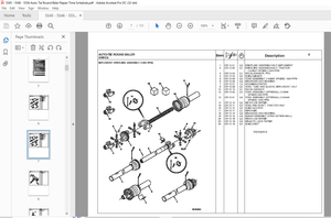
Drive Group, Part No1404492 RevA 9-6
Traction Motor Assembly, Part No1404415 RevC 9-8
Drive Assembly, Part No1400645 RevE 9-12
Idler Assembly for Steering, Part No1401239 RevB 9-14
Chain Assembly for Steering, Part No1400109 RevB 9-16
Drive Unit, Dual Chain, Part No1400695 RevA 9-17
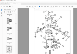
Hydraulic Group, Part No1404493 Rev H 9-21
Hydraulic Spool Valve Assembly, Part No1400642 RevG 9-24
Stack Valve, Part No1400270 RevA 9-26
Pump Motor Assembly, Part No1404416 RevD 9-30
Gear Pump Part No1400269 RevA 9-32
Pump & Motor Assembly, Power Steering, Part No37506 RevA 9-34
Steering Pump Electric Motor, Part No51735 RevB 9-36
Pump, Hydraulic, Steer, Part No51734 RevA 9-39
Hydraulic Reservoir Assembly, Part No1400258 RevE 9-40
Oil Filter Assembly, Part No1400646 RevE 9-42
Hydraulic Assembly, Power Steer, Part No1400649 RevC 9-44
Steering Motor, Part No25950 RevA 9-46
Manifold Assembly, Part No1402869 RevB 9-48
Operator Console Group, Part No1404163 RevG 9-52
Console Panel Assembly, Part No1400498 RevD 9-54
Service Brake Components, Part No1400648 RevH 9-56
Master Cylinder, Part No20210 RevA 9-58
Steering Components, Part No1400650 Rev G 9-60
Steering Column, 10", Part No1400968 RevA 9-63
Electrical Components, Part No1401464 RevE 9-66
Instrument Panel Assembly, Hi-Lo, Part No1404539 RevB 9-68
Side Console Assembly, Hi-Lo, Part No1404068 RevC 9-70
Joystick Assemblies, Part Nos1406119 & 1406120 9-72
Console Cover Assembly, Part No1401860 RevA 9-74
Final Assembly Group, Part No1400639 RevN 9-76
Fluids Group, Part No1404480 RevD 9-81
Rear Compartment Group, Part No1401994 RevH 9-82
Electrical Group Type E, Part No1404478 RevJ 9-86
Battery Connector Subassembly, Part No1401475 RevC 9-88
Panel, Contactor w/o Box, Part No1405740 RevA 9-91
Contactor, Main Pump SPNO, 300A, Part No28889 RevD 9-94
Forward-Reverse Contactor FR, 150A, Part No1401978 RevA 9-96
Steering Pump Contactor AH, 100A, Part No1401980 RevA 9-100
"LX" SCR Control Panel, Part No52511 RevA 9-102
Parking Brake Cable, Part No1400696 9-107
Parking Brake Cable, Part No1400697 9-107
Overhead Guard Group, Part No1400634 RevD 9-108
Seat Group, Part No1404479 RevA 9-111
Load Wheel Group, Part No1400636 RevD 9-112
Pivot/shift Group, Part No1401784 RevF 9-117
vi
Shift Cylinder Components, Part No1405452 RevD 9-118
Shift Cylinder Assemblies, Part Nos1401785/1401786 9-120
Shift Cylinders, Part Nos1401473 (LH), 1402731 (RH) 9-122
Tilt Cylinder 300 Bore, Part No1400153 RevA 9-126
Crosshead & Pivot Assembly, Part No1400653 RevG 9-132
Bar, Lower Support Assembly, Part No1401003 RevB 9-134
Identification Group, Standard, Part No1400641 RevK 9-136
Identification Group, Additions Type "E", Part No1404481 9-141
vii
List of illustrations
Figure 1-1 Fork Lift Truck Operational Modes 1-1
Figure 2-1 Handset and Location of Connections on SCR 2-4
Figure 3-1 Location of Operating Controls 3-3
Figure 3-2 Location of Seat Adjustment Controls 3-4
Figure 3-3 Unlatching the Fork 3-6
Figure 3-4 Fork Latch in Secured Position 3-7
Figure 3-5 Aligning the Truck to the Rack 3-8
Figure 3-6 Shifting and Pivoting a Load in or Out of the Rack 3-8
Figure 3-7 Inserting or Withdrawing a Load Using Shift 3-9
Figure 4-1 Power Steering System Fluid Flow 4-4
Figure 4-2 Power Steering System, Simplified Diagram 4-4
Figure 4-3 Main Pump, Simplified Diagram 4-5
Figure 4-4 Pivot/Tilt System, Simplified Diagram 4-5
Figure 4-5 Tilt System Anti-Cavitation Circuit 4-6
Figure 4-6 Lift System, Simplified Diagram 4-6
Figure 4-7 Shift System, Simplied Diagram 4-7
Figure 4-8 Motor Control Circuit, Simplified Schematic 4-7
Figure 4-9 Forward and Reverse Contactor Circuit, Schematic 4-8
Figure 4-10 Electrical Interlocks, Simplified Schematic 4-8
Figure 5-1 Truck Lubrication Points 5-7
Figure 5-2 Measuring Fork Wear 5-10
Figure 5-3 Measuring Fork Distortion 5-10
Figure 5-4 Maximum Chain Elongation 5-10
Figure 5-5 Brush Rigging 5-11
Figure 6-1 Electrical Schematic 6-7
Figure 6-2 Electrical Wiring Diagram 6-9
Figure 6-3 Hydraulic Schematic 6-11
Figure 7-1 Brake Pedal Adjustment 7-2
Figure 7-2 Valve Stack, Location of Gauge Connections 7-4
Figure 7-3 Suggested Support Fixture and Cradle 7-6
Figure 7-4 Mast Lifting 7-7
Figure 7-5 Blocking the Mast 7-7
Figure 7-6 SCR Logic Card Retaining Screws 7-8
Figure 7-7 Steering Head Hydraulic Lines 7-9
Figure 7-8 Lifting the Drive Motor 7-10
Figure 7-9 Retaining Ring Removal 7-13
Figure 7-10 Gland Bushing Removal 7-13
Figure 7-11 Centering Spring Removal 7-14
viii
Figure 7-12 Removing Check Valve from Steering Head 7-14
Figure 7-13 Clamping Motor to Detach End Cap 7-15
Figure 7-14 Clamping Motor to Detach Flange 7-15
Figure 7-15 Prying Seals Out of Flange • 7-16
Figure 7-16 Contact Pattern on Bevel Gear 7-18
Figure 7-17 Installing Centering Springs 7-20
Figure 7-18 Installing Drive Bearing 7-20
Figure 7-19 Installing Steering Head Drive 7-21
Figure 7-20 Installing Drive Spacers 7-21
Figure 7-21 Tightening Order for End Cap Bolts 7-21
Figure 7-22 Breaking Sharp Corners of Seal Seat 7-22
Figure 7-23 Installing Flange Seal 7-22
Figure 7-24 Alignment of Timing Dot 7-23
Figure 7-25 Brake Assembly Replacement 7-24
Figure 7-26 Centering Spring in Valve Body 7-25
Figure 7-27 Removing the Directional Control Switch 7-26
List of Tables
Table 1-1 General Specifications 1-3
Table 1-2 Dimensions of Triplex Masts for SLT22 & SLT30 Trucks 1-4
Table 2-1 Specific Gravity Corrections for Electrolyte Temperature 2-3
Table 2-2 Recommended Parameters for SCR Controller 2-7
Table 5-1 Preventive Maintenance Schedule 5-3
Table 5-2 Recommended Lubricants 5-8
Table 5-3 Acceptable Y Distances 5-9
ix
IMAGES PREVIEW OF THE MANUAL:
S.S 05/24
More products