$37
EP CQD16 20RVF RV CQD16NRVF NRV Electric Reach Truck Service Manual
EP CQD16/20RVF/RV CQD16NRVF/NRV Electric Reach Truck Service Manual – PDF DOWNLOAD
FILE DETAILS:
EP CQD16/20RVF/RV CQD16NRVF/NRV Electric Reach Truck Service Manual – PDF DOWNLOAD
Language : English
Pages : 251
Downloadable : Yes
File Type : PDF
IMAGES PREVIEW OF THE MANUAL:
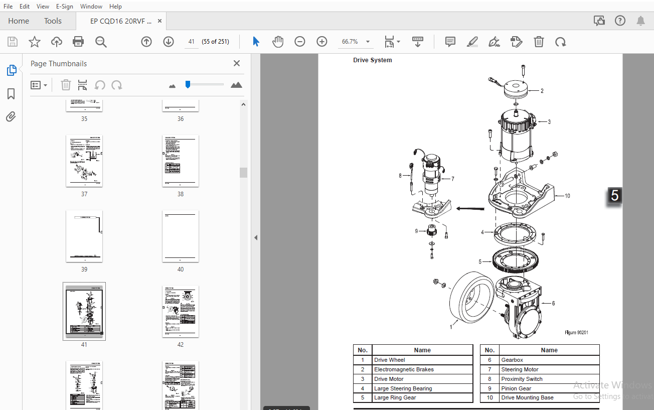
TABLE OF CONTENTS:
EP CQD16/20RVF/RV CQD16NRVF/NRV Electric Reach Truck Service Manual – PDF DOWNLOAD
1 INFORMATION & SPECIFICATIONS 1
1 1 After-sales Service Platform 3
1 2 Introduction 4
1 3 Common Tools 5
1 4 General Tightening Torques 6
2 MAINTENANCE 9
2 1 Overview 11
2 2 Maintenance 12
2 2 1 Cleaning 12
2 2 2 Inspection 12
2 2 3 Lubrication 17
3 STRUCTURE & FUNCTIONS 21
3 1 Structure & Functions 23
3 1 1 Travel Switch 23
3 1 2 Emergency Stop Switch 23
3 1 3 Key Switch 23
3 1 4 Horn Button 23
3 1 5 Control Switch (RVF/NRVF) 24
3 1 6 Control Switch (RV/NRV) 24
3 1 7 Instrument 24
3 1 8 Horn 24
3 1 9 Fan 25
3 1 10 Accelerator Pedal 25
3 1 11 Brake Pedal 25
3 1 12 Foot Switch 25
3 1 13 Warning Light 26
3 1 14 Headlight 26
3 1 15 Rocker Switch 26
3 1 16 Stepper Motor 26
3 1 17 AC2 Controller(TranceController) 27
3 1 18 AC2 Controller (Pump Controller) 27
3 1 19 EPS-AC0 Controller 27
3 1 20 DC-DC Converter 27
3 1 21 Main Contactor 28
3 1 22 Solenoid Valve Controller(RVF/NRVF) 28
3 1 23 Multi-way Solenoid Valve (RVF/NRVF) 28
3 1 24 Multi-way Manual Valve (RV/NRV) 28
3 1 25 Pump Motor 29
3 1 26 Gear Pump 29
4 CHASSIS SYSTEM 31
4 1 Load Wheel 33
4 1 1 Removal and Installation 33
4 1 2 Faults and Causes 33
4 2 Caster 34
4 2 1 Removal and Installation 34
4 3 Brake Pedal 35
4 3 1 Removal and Installation 35
4 3 2 Faults and Causes 36
4 4 Seat 36
4 4 1 Removal and Installation 36
4 5 Brakes 37
4 5 1 Removal and Installation 37
4 5 2 Faults and Causes 38
5 DRIVE SYSTEM 39
5 1 Drive Wheel 42
5 1 1 Removal and Installation 42
5 1 2 Faults and Causes 42
5 2 Electromagnetic Brakes 43
5 2 1 Removal and Installation 43
5 2 2 Faults and Causes 44
5 2 3 Checking and Testing 44
5 2 4 Control Circuit Troubleshooting 45
5 3 Drive Motor 46
5 3 1 Removal and Installation 46
5 3 2 Faults and Causes 46
5 3 3 Checking and Testing 47
5 3 4 Control Circuit Troubleshooting 48
5 4 Gearbox 49
5 4 1 Removal and Installation 49
5 4 2 Faults and Causes 49
5 5 Proximity Switch 50
5 5 1 Removal and Installation 50
5 5 2 Faults and Causes 50
5 5 3 Checking and Testing 51
5 5 4 Control Circuit Troubleshooting 51
5 6 Steering Motor 52
5 6 1 Removal and Installation 52
5 6 2 Faults and Causes 52
5 6 3 Checking and Testing 53
5 6 4 Control Circuit Troubleshooting 54
6 OPERATING SYSTEM 55
6 1 Control Lever 57
6 2 Control Panel 57
6 3 Horn Button 58
6 3 1 Removal and Installation 58
6 3 2 Faults and Causes 58
6 3 3 Checking and Testing 58
6 3 4 Control Circuit Troubleshooting 58
6 4 Control Switch (RVF/NRVF) 59
6 4 1 Removal and Installation 59
6 4 2 Faults and Causes 59
6 4 3 Checking and Testing 59
6 4 4 Control Circuit Troubleshooting 60
6 5 Control Switch (RV/NRV) 62
6 5 1 Removal and Installation 62
6 5 2 Faults and Causes 62
6 5 3 Connection Mode 62
6 5 4 Checking and Testing 62
6 5 5 Control Circuit Troubleshooting 63
6 6 Stepper Motor 65
6 6 1 Removal and Installation 65
6 6 2 Faults and Causes 65
6 6 3 Checking and Testing 65
6 6 4 Control Circuit Troubleshooting 65
6 7 Key Switch 66
6 7 1 Removal and Installation 66
6 7 2 Faults and Causes 66
6 7 3 Checking and Testing 66
6 7 4 Control Circuit Troubleshooting 66
6 8 Emergency Switch 67
6 8 1 Removal and Installation 67
6 8 2 Faults and Causes 67
6 8 3 Checking and Testing 67
6 8 4 Control Circuit Troubleshooting 67
6 9 Rocker Switch 68
6 9 1 Removal and Installation 68
6 9 2 Faults and Causes 68
6 9 3 Checking and Testing 68
6 9 4 Control Circuit Troubleshooting 68
6 10 Travel Switch 70
6 10 1 Removal and Installation 70
6 10 2 Faults and Causes 70
6 10 3 Checking and Testing 70
6 10 4 Control Circuit Troubleshooting 70
7 HYDRAULIC SYSTEM 71
7 1 Overview 73
7 1 1 Hydraulic Schematic Diagram RVF/NRVF 74
7 1 2 Hydraulic Schematic Diagram RV/NRV 75
7 2 Hydraulic Power Unit 76
7 2 1 Removal and Installation 76
7 3 Pump Motor 76
7 3 1 Removal and Installation 76
7 3 2 Faults and Causes 76
7 3 3 Checking and Testing 77
7 3 4 Control Circuit Troubleshooting 78
7 4 Multi-way Reversing Solenoid Valve (RVF/NRVF) 79
7 4 1 Removal and Installation 79
7 4 2 Interface Description 79
7 4 3 Faults and Causes 80
7 4 4 Checking and Testing 80
7 4 5 Control Circuit Troubleshooting 80
7 5 Solenoid Valve (RVF/NRVF) 81
7 5 1 Faults and Causes 81
7 5 2 Checking and Testing 81
7 5 3 Control Circuit Troubleshooting 82
7 6 Multi-way Reversing Manual Valve (RV/NRV) 83
7 6 1 Removal and Installation 83
7 6 2 Interface Description 84
7 6 3 Faults and Causes 84
7 6 4 Checking and Testing 84
7 7 Gear Pump 85
7 7 1 Removal and Installation 85
7 7 2 Faults and Causes 85
7 7 3 Checking and Testing 85
7 8 Reach Cylinder 86
7 8 1 Cylinder Removal Precautions 86
7 8 2 Cylinder Installation Precautions 87
7 8 3 Removal and Installation 88
7 8 4 Cylinder Maintenance 89
7 9 Hydraulic Troubleshooting 90
7 10 Hydraulic Symbol 91
8 ELECTRICAL SYSTEM 93
8 1 Controller 95
8 1 1 Removal and Installation 95
8 1 2 Controller Interface Function 97
8 2 Fuse 107
8 2 1 Location of Fuses 107
8 2 2 Checking and Testing 108
8 3 Main Contactor 109
8 3 1 Removal and Installation 109
8 3 2 Faults and Causes 109
8 3 3 Checking and Testing 110
8 3 4 Control Circuit Troubleshooting 110
8 4 Height Display (RVF/NRVF) 111
8 4 1 Removal and Installation 111
8 4 2 Faults and Causes 111
8 4 3 Checking and Testing 111
8 4 4 Control Circuit Troubleshooting 112
8 5 Limit Switch 113
8 5 1 Removal and Installation 113
8 5 2 Connection Mode 113
8 5 3 Faults and Causes 114
8 5 4 Checking and Testing 114
8 5 5 Control Circuit Troubleshooting 114
8 6 Accelerator Pedal 116
8 6 1 Removal and Installation 116
8 6 2 Faults and Causes 116
8 6 3 Checking and Testing 116
8 6 4 Control Circuit Troubleshooting 117
8 7 Foot Switch 118
8 7 1 Removal and Installation 118
8 7 2 Faults and Causes 118
8 7 3 Checking and Testing 118
8 7 4 Control Circuit Troubleshooting 119
8 8 DC-DC Converter 120
8 8 1 Removal and Installation 120
8 8 2 Faults and Causes 120
8 8 3 Checking and Testing 120
8 8 4 Control Circuit Troubleshooting 120
8 9 Warning Light / Headlight 121
8 9 1 Removal and Installation 121
8 9 2 Faults and Causes 121
8 9 3 Checking and Testing 121
8 9 4 Control Circuit Troubleshooting 121
8 10 Cooling Fan 122
8 10 1 Removal and Installation 122
8 10 2 Faults and Causes 122
8 10 3 Checking and Testing 122
8 10 4 Control Circuit Troubleshooting 122
8 11 Seat Switch 124
8 11 1 Removal and Installation 124
8 11 2 Faults and Causes 124
8 11 3 Checking and Testing 124
8 11 4 Control Circuit Troubleshooting 124
8 12 Instrument 125
8 12 1 Instrument Operation Schematics 125
8 13 Handheld Unit (Optional) 129
8 13 1 Handheld Unit Connection 129
8 13 2 Handheld Unit Menu Options 129
8 13 3 TESTER Menu 131
8 14 Controller Error Message 133
8 14 1 Tractiong/Pump Controller 133
8 14 2 Steering Controller (EPS-ACO) 138
8 14 3 SICOS Controller 147
8 14 4 Solenoid Valve Controller 148
8 15 Electrical Schematic Diagrams RVF/NRVF 149
8 15 1 Electrical Schematic Diagram RVF/NRVF (1/6) 149
8 15 2 Electrical Schematic Diagram RVF/NRVF (2/6) 150
8 15 3 Electrical Schematic Diagram RVF/NRVF (3/6) 151
8 15 4 Electrical Schematic Diagram RVF/NRVF (4/6) 152
8 15 5 Electrical Schematic Diagram RVF/NRVF (5/6) 153
8 15 6 Electrical Schematic Diagram RVF/NRVF (6/6) 154
8 16 Electrical Schematic Diagrams RV/NRV 155
8 16 1 Electrical Schematic Diagram RVF/NRVF (1/5) 155
8 16 2 Electrical Schematic Diagram RVF/NRVF (2/5) 156
8 16 3 Electrical Schematic Diagram RVF/NRVF (3/5) 157
8 16 4 Electrical Schematic Diagram RVF/NRVF (4/5) 158
8 16 5 Electrical Schematic Diagram RVF/NRVF (5/5) 159
8 17 Cable Wiring Diagrams (RVF/NRVF) 160
8 18 Cable Wiring Diagrams (RV/NRV) 161
8 19 Wiring Harness and Connectors (RVF/NRVF) 162
8 20 Wiring Harness and Connectors (RV/NRV) 163
9 TROUBLESHOOTING 165
9 1 Preparation Before Troubleshooting 167
9 1 1 Check the Voltage of Battery 167
9 2 Troubleshooting Solutions of Common Faults 168
APPENDIX
A SERVICE MANUAL – MAST 175
A1 Two-stage Mast 177
A1-1 Removal and Installation 177
A1-2 Lifting Chains 178
A1-2 1 Chain Adjustment 178
A1-2 2 Chain Replacement 179
A1-3 Mast Tubing 180
A1-4 Lift Cylinder 181
A1-4 1 Cylinder Removal (with mast on the vehicle) 181
A1-4 2 Cylinder Maintenance 182
A1-4 3 Cylinder Installation 182
A1-5 Tilt Cylinde 183
A1-5 1 Cylinder Removal 183
A1-5 2 Cylinder Maintenance 183
A1-5 3 Cylinder Installation 184
A1-6 Built-in Side Shifter 184
A1-6 1 Side Shifter Removal 184
A1-6 2 Side Shifter Installation 184
A1-6 3 Side Shifter Maintenance 185
A2 Three-stage Mast(Lifting Height ≤ 7 5 m) 186
A2-1 Removal and Installation 186
A2-2 Lifting Chains 187
A2-2 1 Chain Adjustment 187
A2-2 2 Chain Replacement 188
A2-2 2 1 Mast Chains 188
A2-2 2 2 Fork Carriage Chains 188
A2-3 Mast Tubing 191
A2-4 Lift Cylinder 193
A2-4 1 Cylinder Removal 193
A2-4 2 Cylinder Maintenance 194
A2-4 3 Cylinder Installation 195
A2-5 Tilt Cylinde 196
A2-5 1 Cylinder Removal 196
A2-5 2 Cylinder Maintenance 196
A2-5 3 Cylinder Installation 197
A2-6 Built-in Side Shifter 197
A2-6 1 Side Shifter Removal 197
A2-6 2 Side Shifter Installation 197
A2-6 3 Side Shifter Maintenance 198
A3 Three-stage Mast (8 0 m≤ Lifting Height ≤ 9 5 m) 199
A3-1 Removal and Installation 199
A3-2 Lifting Chains 200
A3-2 1 Chain Adjustment 200
A3-2 2 Chain Replacement 201
A3-2 2 1 Mast Chains 201
A3-2 2 2 Fork Carriage Chains 201
A3-3 Mast Tubing 204
A3-4 Lift Cylinder 206
A3-4 1 Cylinder Removal 206
A3-4 2 Cylinder Maintenance 207
A3-4 3 Cylinder Installation 208
A3-5 Tilt Cylinde 209
A3-5 1 Cylinder Removal 209
A3-5 2 Cylinder Maintenance 209
A3-5 3 Cylinder Installation 210
A3-6 Built-in Side Shifter 210
A3-6 1 Side Shifter Removal 210
A3-6 2 Side Shifter Installation 210
A3-6 3 Side Shifter Maintenance 211
A4 Three-stage Mast(10 m≤ Lifting Height ≤ 11 m) 212
A4-1 Removal and Installation 212
A4-2 Lifting Chains 213
A4-2 1 Chain Adjustment 213
A4-2 2 Chain Replacement 214
A4-2 2 1 Mast Chains 214
A4-2 2 2 Fork Carriage Chains 214
A4-3 Mast Tubing 217
A4-4 Lift Cylinder 219
A4-4 1 Cylinder Removal 219
A4-4 2 Cylinder Maintenance 220
A4-4 3 Cylinder Installation 221
A4-5 Tilt Cylinde 222
A4-5 1 Cylinder Removal 222
A4-5 2 Cylinder Maintenance 222
A4-5 3 Cylinder Installation 223
A4-6 Built-in Side Shifter 223
A4-6 1 Side Shifter Removal 223
A4-6 2 Side Shifter Installation 223
A4-6 3 Side Shifter Maintenance 224
B SERVICE MANUAL – BATTERY 225
B1 Lead-acid Battery 227
B1-1 Safety and Warnings 227
B1-2 Use of Battery 227
B1-2 1 Pre-use Checks 227
B1-2 2 Discharging 227
B1-2 3 Charging 228
B1-2 4 Temperature 228
B1-3 Maintenance & Care 228
B1-3 1 Daily Maintenance 228
B1-3 2 Weekly Maintenance 228
B1-3 3 Monthly Maintenance 229
B1-3 4 Care 229
B1-4 Storage 230
B1-5 Troubleshooting 230
B2 Maintenance-free Battery 233
B2-1 Safety and Warnings 233
B2-2 Use of Battery 233
B2-2 1 Pre-use Checks 233
B2-2 2 Discharging 233
B2-2 3 Charging 234
B2-3 Maintenance & Care 234
C SCHEDULE 235
More products