$45
Epson 2000 Service Manual SEIJ99006 - PDF DOWNLOAD
Epson 2000 Service Manual SEIJ99006 - PDF DOWNLOAD
FILE DETAILS:
Epson 2000 Service Manual SEIJ99006 - PDF DOWNLOAD
Language :English
Pages :169
Downloadable : Yes
File Type : PDF
IMAGES PREVIEW OF THE MANUAL:
DESCRIPTION:
Epson 2000 Service Manual SEIJ99006 - PDF DOWNLOAD
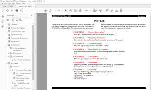
PREFACE This manual describes basic functions, theory of electrical and mechanical operations, maintenance and repair procedures of EPSON STYLUS Scan 2000. The instructions and procedures
- included herein are intended for the experienced repair technicians, and attention should be given to the precautions on the preceding page. The chapters are organized as follows:
CHAPTER 1. “Product Description”
Provides a general overview and specifications of the product.
CHAPTER 2. “Operating Principles”
Describes the theory of electrical and mechanical operations of the product.
CHAPTER 3. “Troubleshooting”
Provides step-by-step procedures for troubleshooting.
CHAPTER 4. “Disassembly & Assembly”
Describes step-by-step procedures for disassembling and assembling the product.
CHAPTER 5. “Adjustment”
Provides Epson-approved methods for adjustment.
CHAPTER 6. “Maintenance”
Provides preventive maintenance procedures and the lists of Epson-approved
lubricants and adhesives required for servicing the product.
CHAPTER 7. “Appendix”
Provides the following additional information for reference:
• EEPROM Address Map
• Connector Pin Assignment
• Schematics
• Circuit Diagrams
TABLE OF CONTENTS:
Epson 2000 Service Manual SEIJ99006 - PDF DOWNLOAD
Contents 6
Product Description 8
11 Features 9
12 General Specifications 10
121 Local copy 10
122 Scan area 10
123 Print area 11
124 Printer 12
125 Scanner 15
126 Common 16
13 Interfaces 17
131 Printer interface 17
132 Scanner interfaces 22
14 Control Panel 23
141 Buttons 23
142 Control panel indicates the printer’s condition 25
143 Initialization 26
15 Stylus Scan Errors 28
16 Physical Characteristics 29
161 Dimensions 29
162 Weight 29
163 External view 29
Operating Principles 30
21 General 31
22 Printer Mechanism Operation 32
221 Printing Mechanism 33
222 Printing Process 34
223 Carriage Mechanism 35
224 Paper Feeding Mechanism 37
225 Ink System 42
226 Pump, Carriage Lock, Head Cleaner Mechanism 43
23 Scanner Mechanism Operation 46
231 Mechanism 46
24 Local and PC-Centric Copy Principles 47
241 Local copy process 47
242 PC-Centric copy process 47
25 Electrical Circuit Operating Principles 49
251 B101 PSB/PSE Board 50
252 B101 MAIN Board 53
Troubleshooting 56
31 Unit Level Troubleshooting 57
311 Printer/Scanner does not operate at power on 58
312 Error is detected 59
313 Failure occurs during printing 59
314 Printer does not feed paper correctly 60
315 Control panel operation is abnormal 60
32 Repair of the Printer Mechanism 61
33 Troubleshooting the Scanner 65
331 Scanner Troubleshooting Flowcharts 65
332 Scanner troubleshooting check points 66
34 Troubleshooting the Motors and Sensors 69
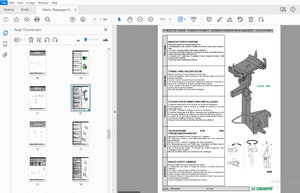
Disassembly & Assembly 70
41 Overview 71
411 Precautions for Disassembling the Printer 71
412 Tools 72
413 Screw Numbering System and Specifications 73
414 Service Checks After Repair 74
42 Disassembly Procedures 76
421 Removing the Housing 77
422 Removal of printer consumables 81
423 Removing the Circuit Board Tray 84
424 Removing the Scanner Mechanism 88
425 Disassembling the Printer Mechanism 94
Adjustment107
51 Required Adjustments108
511 Adjustment Tools Required110
52 Printer Adjustment110
521 Printer hardware adjustments111
53 Using the Service-Adjustment Program113
531 Installing the program113
532 Opening the Start-up menu114
533 Initial Ink Charge Operation119
534 Bi-D Adjustment120
535 Head Cleaning Operation121
536 Head Voltage ID Input122
537 Head Angular Adjustment123
538 Ink draining125
54 Scanner Adjustment125
Maintenance126
61 Printer-Related Maintenance127
62 Cleaning128
621 Exterior128
622 Inside128
63 Lubrication129
631 Printer Mechanism129
Appendix137
Appendix137
71 Connector Summary138
711 Board Connector Summary139
712 Connector Pin Assignment140
72 EEPROM Address Map143
73 Exploded Diagrams148
74 Parts List155
75 Component Layout160
76 Circuit Diagrams165
S.M 26/2/2025
More products