$35
Epson 2000 Service Manual - PDF DOWNLOAD
Epson 2000 Service Manual - PDF DOWNLOAD
FILE DETAILS:
Epson 2000 Service Manual - PDF DOWNLOAD
Language :English
Pages :204
Downloadable : Yes
File Type : PDF
IMAGES PREVIEW OF THE MANUAL:
DESCRIPTION:
Epson 2000 Service Manual - PDF DOWNLOAD
Safety Information
To prevent accidents during a maintenance procedure, strictly observe the Warnings and Cautions. Do not do anything that is dangerous or not within
the scope of this document.
Do not do anything that is dangerous even if not specifically described in this manual. In addition to the descriptions below and those given in this
manual, there are many situations and circumstances that are dangerous. Be aware of these when you are working with the printer.
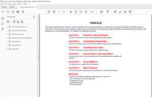
TABLE OF CONTENTS:
Epson 2000 Service Manual - PDF DOWNLOAD
Product Descriptions 11
11 Overview 12
12 Controller Unit Specifications 15
121 Controller Basic Specifications 15
122 Engine Specifications 15
123 Process Specification 20
124 Paper Specification 21
125 Sensors 23
126 Reliability, Durability, Serviceability 26
127 Operating Conditions (Including Consumables) 27
128 Storage and Transport Environments (Including Consumables) 28
129 Electrical Characteristics 29
1210 Applicable Standards and Regulations 30
1211 Consumable Specifications 31
12111 Developer cartridges 31
12112 Photoconductor kit 32
12113 Waste Toner Collector 32
12114 Fuser Kit 33
12115 Transfer Belt Unit 33
13 Interface Specifications 34
131 Parallel Interface Specifications 34
132 Ethernet Interface Specifications 35
133 Optional Interface Specifications 35
14 Control Panel 37
141 Exterior View and Names 37
1411 LED Description 37
142 Button Functions 38
143 One Touch Setting Modes 39
144 Panel Setting Item List 40
145 Explanation of Each Setting Menu and Items 47
1451 Printing Menu 47
1452 Tray Menu 48
1453 Config Menu 48
1454 Setup Menu 50
1455 Maintenance Menu 51
146 Service Operations 52
15 About RAM Expansion 53
16 Engine Restrictions 54
161 Restriction on Printing Speed 54
1611 Toner Duty Restrictions 54
17 Handling Precautions 55
171 Caution when there is a Power Failure 55
172 Caution Regarding High Temperature Parts 55
Operating Principles 57
21 Mechanism Overview 58
211 Gear Roller Arrangement 59
22 Printing Process 67
221 Paper Feed Mechanism 68
2211 Tray 1 68
2212 Tray 2 (Cassette 1) 69
2213 Tray 3 (Cassette 2) 69
2214 Timing Roller 70
222 Charging Process 70
223 Exposure Process 72
224 Development Process 73
2241 Toner Cartridge Rack 73
2242 Toner Cartridge 75
2243 Names of Unit Contacting Terminals 78
225 Transfer Process 79
2251 Mid-Transfer Belt Unit 79
2252 Mid-Transfer 79
2253 Paper Transfer 80
226 Waste Toner Bottle 83
227 Suction Process 84
228 Fusing Process 84
2281 Fusing Unit 84
2282 Fusing Temperature Control 86
2283 Fusing Oil Roll 89
229 Paper Eject Process 89
2291 Duplex Unit (option) 90
23 Controller Board (C314MAIN) Operating Principles 92
231 Specification 92
Troubleshooting 93
31 Troubleshooting Method 94
311 Troubleshooting Procedure 94
312 Power is not Applied 96
313 Self Check Function 96
32 Printer Message 98
3201 Messages 98
321 Printer Message Details of Status Messages and Remedies101
322 Details of Error Messages and Remedies101
323 Details of Warning Messages and Remedies104
324 Service Call Error Messages106
3241 Engine Related Service Call Error Messages106
3242 Engine Related Service Call Error Troubleshooting107
3243 Controller Related Service Call Error Messages114
33 Image Quality Troubleshooting116
Disassembly and Assembly119
41 Overview120
411 Cautions120
412 Service Tools120
413 Screws, Small Parts121
414 Fuses121
42 Disassembling Procedure122
421 Overview122
422 Before Disassembling the Printer123
423 Outer Cover Removal123
4231 Front Cover Removal123
4232 Operation Panel Removal124
4233 Front Inner Cover Removal124
4234 Top Cover Removal125
4235 Left Cover Removal125
4236 Rear Controller Cover Removal126
4237 Rear Cover Removal127
4238 Rear Right Cover Removal127
4239 Left Rear Cover Removal128
42310 Rear Left Cover Removal128
424 C314MAIN Board129
4241 C314MAIN Board Removal129
4242 Controller Box Removal131
425 MCU (PWB-A Board) Removal131
426 PU1 (Power Supply Board) Removal132
427 High Voltage Board (HV1, HV2) Removal133
4271 HV1 (High Voltage Board) Removal133
4272 HV2 (High Voltage Board) Removal133
428 Fusing Motor Removal134
429 Transfer Motor Removal135
4291 PU1 Support Plate Removal135
4292 Transfer Motor Removal135
4210 Fusing Pressure Motor Removal136
4211 Fan Motor Removal136
42111 Power Supply Fan Motor Removal136
42112 Fusing Fan Motor Removal137
42113 Transfer Belt Fan Motor Removal137
42114 Cooling Fan Motor Removal138
4212 Laser Safety Switch (CDRH-SW) Removal138
4213 Waste Toner Full Sensor Removal139
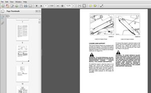
4214 MP Tray Paper Load140
42141 Paper Load Cover Removal140
42142 MP Tray Paper Load Solenoid Removal140
4215 MP Tray Paper Load Unit141
42151 Front Bearing for the MP Tray Paper Load Unit Removal141
42152 MP Tray Paper Load Unit Removal141
4216 Paper Cassette142
42161 Paper Size Switch Removal142
42162 Paper Near Empty Sensor Removal142
42163 Cassette Paper Load Solenoid Removal142
4217 Transfer Mechanism143
42171 Timing Roller Solenoid Removal143
42172 Middle Roller Solenoid Removal143
42173 Lower Paper Load Guide Removal144
42174 Timing Sensor Removal144
4218 OHP Sensor Removal144
4219 Developer Mechanism145
42191 Toner Empty Sensor Removal145
42192 Front Side Rack Bearing Removal145
42193 Rack Lock Lever Removal146
42194 Rack Black Position Sensor Removal146
42195 Developer Motor Assy Removal147
42196 Rear Rack Bearing Removal147
42197 Rack Removal148
4220 PH (Print Head) Mechanism149
42201 PH Connector Removal149
42202 PH Cover Removal149
42203 PH Removal150
4221 Transfer Mechanism150
42211 Transfer Roller Pressure Solenoid Removal150
42212 Transfer Roller Pressure Sensor Removal151
42213 Suction Fan Motor Removal152
42214 Middle Paper Sensor Removal152
4222 Belt Cleaner Mechanism153
42221 Left Upper Support Plate Removal153
42222 Left Frame Plate Removal153
42223 Belt Cleaner Estrangement Position Sensor Removal154
42224 PWB-I (Belt Cleaner Control Board) Removal154
4223 Fusing Mechanism155
42231 Pressure Roller Estrangement Sensor Removal155
4224 Paper Eject Mechanism155
42241 Paper Eject Sensor Removal155
4225 Rack Motor Assy156
42251 Power Switch Removal156
42252 Rack Motor Assy Removal156
4226 Duplex Unit157
42261 Duplex Paper Feed Sensor Removal157
42262 Duplex Unit Board Cover Removal157
42263 Duplex Unit Board (PWB-AD) Removal158
42264 Motor Cover Removal158
42265 Motor Plate Removal159
42266 Reverse Motor Removal159
42267 Duplex Paper Load Motor Removal159
43 Program ROM Update160
431 Program ROM Update160
4311 Error Indication and Remedies160
432 DIMM Module Copy161
Adjustment162
51 Adjustment163
Maintenance164
61 Maintenance165
611 Replacement Parts165
612 Cleaning165
Appendix166
71 Overview167
711 MCU Internal Connection Diagram167
72 Component Layout169
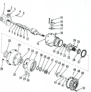
73 Exploded Diagram172
74 Parts List189
75 Circuit Diagram197
S.M 26/2/2025
More products