$35
Epson EPL-5800 Service Manual - PDF DOWNLOAD
Epson EPL-5800 Service Manual - PDF DOWNLOAD
FILE DETAILS:
Epson EPL-5800 Service Manual - PDF DOWNLOAD
Language :English
Pages :116
Downloadable : Yes
File Type : PDF
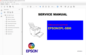
IMAGES PREVIEW OF THE MANUAL:
DESCRIPTION:
Epson EPL-5800 Service Manual - PDF DOWNLOAD
PREFACE
This manual describes basic functions, theory of electrical and mechanical operations, maintenance and repair procedures of EPL-5800. The instructions and procedures included herein are intended for the experienced repair technicians, and close attention should be given to the precautions on the preceding page. Chapters are organized as follows:
CHAPTER 1. PRODUCT DESCRIPTIONS
Provides a general overview and specifications of the product.
CHAPTER 2. OPERATING PRINCIPLES
Describes the theory of electrical and mechanical operations of the product.
CHAPTER 3. TROUBLESHOOTING
Provides the step-by-step procedures for troubleshooting.
CHAPTER 4. DISASSEMBLY AND ASSEMBLY
Describes the step-by-step procedures for disassembling and assem- bling the product.
CHAPTER 5. ADJUSTMENT
Provides adjusting procedures.
CHAPTER 6. MAINTENANCE
Provides preventive maintenance procedures.
APPENDIX
Provides the following addition information for reference:
- Connector Pin Diagram
- Circuit Board Component Layout
- Parts Lists & Exploded Diagrams
- Circuit Schematics
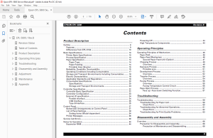
TABLE OF CONTENTS:
Epson EPL-5800 Service Manual - PDF DOWNLOAD
EPL-5800 / RevB 1
Revision Status 5
Table of Contents 6
Product Description 8
11 Outline 9
111 Features 9
Engine Features 9
Controller Features 9
Software FEATURE 9
112 Differences from EPL-5700 10
12 Basic Specifications 10
121 Printer Basic Specifications 10
122 Process Specification 13
123 Paper Specification 14
1231 Paper Type 14
1232 Paper Feeding 14
1233 Printable Area (Engine) 15
124 Reliability, Durability, Serviceability 15
125 Operating Conditions Including Consumables 17
126 Storage and Transport Environments Including Consumables 18
127 Electric Characteristics 18
128 Applicable Standards and Regulations 19
Safety standards 19
Safety regulations (laser radiation) 19
EMC 19
129 Consumable Specifications 20
1291 Specifications 20
1292 Storage and Transport Environments 20
14 Controller Specification 22
141 Controller Basic Specification 22
142 Controller Configuration 23
Jumper Setting 23
Destination Settings a4/lETTER SELECTION 23
143 External I/F specification 24
1431 Parallel Interface 24
1432 USB Interface 25
1433 Type B Interface 25
15 Control Panel 27
151 Button/LED Arrangements on Control Panel 27
152 List of Panel Settings 28
1521 Setting Items (Model-dependent) 34
MP mode 34
Tray Assign 34
Toner Out 34
Paper Type 34
MP Type, LC Type 34
Quantity 35
Parallel I/F, USB I/F, AUX I/F 35
153 Printer Messages 36
16 Service Call Errors 39
Hex dump 43
Toner reset 43
Photoconductor life reset 43
EEPROm initialization 43
Panel setting value initialization 43
Update program rom 43
18 Notes for Operation 44
181 Expansion RAM 44
182 Powering Off 44
183 High-Temperature Components 44
Operating Principles 45
21 Operating Principles of Mechanism 46
211 Paper Path 46
212 Paper Feed Mechanism 46
Multi Paper Feed Tray 46
Paper Empty Sensor 47
2121 Second Paper Feed Unit (Option) 47
mechanism 47
Paper Empty Sensor 48
Cassette Type Sensor 48
213 Charging Process 49
2131 Overview 49
214 Exposure Process 50
Sub Scanning Direction (Vertical Scanning Direction) 50
Main Scanning Direction (Horizontal Scanning Direction) 50
2141 Printable area 51
215 Development Process 52
2151 Overview 52
216 Transfer Process 54
2161 Overview 54
217 Fusing Process 55
2171 Overview 55
2172 Fusing Temperature Control Circuit 55
At 600dpi 56
At 1200dpi 56
218 Paper Eject Process 57
2181 Face up / Face down Switching Function 57
Face down eject 57
Face up eject 57
Troubleshooting 58
31 Troubleshooting 59
311 Troubleshooting for Paper Jam 59
Paper Jam Conditions 59
Resetting the Paper Jam 59
3111 Check Point 60
Paper Jam when the Power is ON 60
Paper Jam from the Paper Feed to the Transport 60
Paper Jam from the Transport to the Paper Eject 60
312 Troubleshooting for Abnormal Operations 61
Abnormal Laser 61
Abnormal Polygon Motor 61
Abnormal Main Motor 61
Abnormal Fan Motor 61
Abnormal Fusing 61
3121 Check Point 62
Abnormal Laser 62
Abnormal Polygon Motor 62
Abnormal Main Motor 62
Abnormal Fan Motor 62
Abnormal Fusing 62
Power Cannot be Turned ON 62
313 Troubleshooting for Print Quality Problems 63
Disassembly and Assembly 65
41 Overview 66
411 Precaution for Disassembly and Assembly 66
4111 Precaution at Maintenance and Disassembling 66
4112 Precaution at Handling the Laser Mechanism 66
4113 Handling Forbidden 66
4114 Precaution at Handling the Print Board 66
Precaution at Transporting and Keeping 66
Precaution at replacing 67
Precaution at Checking 67
4115 Precaution at Handling the Photoconductor (Drum Cartridge) 67
Precaution at Transporting and Keeping 67
Precaution at Handling 67
412 Regularly Replacement Parts 68
413 Service Tools 68
414 Specification for Screws 68
42 Disassembly Procedure 69
421 Preparation before disassembling 70
422 Paper Feed Roller Replacement 70
423 Transfer Roller Replacement 71
424 Paper Empty Sensor (PE1) Removal 72
425 Right Cover Removal 72
426 Control Panel Removal 73
427 Main Control Board (PWB-P) Removal 73
428 Left Cover and Front Cover Removal 74
429 Paper Feed Solenoid (SL1) Removal 74
4210 Top Cover Removal 75
4211 Rear Cover Removal 76
4212 Cooling Fan Removal 76
4213 Main Motor Assembly Removal 77
4214 Fusing Unit Removal 77
4215 Fusing Unit Disassembly 78
4216 Interlock Switch (S2) Removal 80
4217 Print Head Unit (PH) Removal 81
4218 Power Unit (PU1), Paper Feed Sensor (PS1) Removal 81
4219 High Voltage Unit (HV1) Removal 82
4220 Second Paper Feed Roller Replacement 83
4221 Second Paper Feed Unit Removal 83
4222 Relay Board (PWB-A) Removal 84
4223 Second Paper Size Detection Switch (SW21) Removal 85
4224 Second Paper Feed Solenoid (SL21) Removal 85
Adjustment 86
51 Adjustment 87
511 Print Start Position Adjustment 87
Adjustment by actual printing 87
Adjustment by Voltage change 87
512 Interlock Switch Position Adjustment 88
513 USB ID Input 89
Program setup 89
program Operation 89
USB ID confirmation 90
Maintenance 91
61 Maintenance 92
611 User Maintenance on Main Unit 92
612 Maintenance of Consumables 92
613 Maintenance by Service Technicians 93
Appendix 94
71 Overview 95
72 Connectors 95
721 Connection diagrams 95
722 Connector List 95
723 Connector Pin Assignment 96
73 Component Layout 99
74 Circuit Schematics100
75 Parts List104
76 Exploded View Diagrams107
S.M 28/2/2025

