$40
Epson EPL-N2700 Service Manual - PDF DOWNLOAD
Epson EPL-N2700 Service Manual - PDF DOWNLOAD
FILE DETAILS:
Epson EPL-N2700 Service Manual - PDF DOWNLOAD
Language :English
Pages :165
Downloadable : Yes
File Type : PDF
IMAGES PREVIEW OF THE MANUAL:
DESCRIPTION:
Epson EPL-N2700 Service Manual - PDF DOWNLOAD
Safety Information
To prevent accidents during a maintenance procedure, strictly observe the Warnings and Cautions. Do not do anything that is dangerous or not within
the scope of this document.
Do not do anything that is dangerous even if not specifically described in this manual. In addition to the descriptions below and those given in this
manual, there are many situations and circumstances that are dangerous. Be aware of these when you are working with the printer.
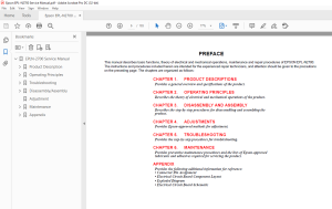
PREFACE
This manual describes basic functions, theory of electrical and mechanical operations, maintenance and repair procedures of EPSON EPL-N2700.
The instructions and procedures included herein are intended for the experienced repair technicians, and attention should be given to the precautions
on the preceding page. The chapters are organized as follows:
CHAPTER 1. PRODUCT DESCRIPTIONS
Provides a general overview and specifications of the product.
CHAPTER 2. OPERATING PRINCIPLES
Describes the theory of electrical and mechanical operations of the product.
CHAPTER 3. DISASSEMBLY AND ASSEMBLY
Describes the step-by-step procedures for disassembling and assembling the
product.
CHAPTER 4. ADJUSTMENTS
Provides Epson-approved methods for adjustment.
CHAPTER 5. TROUBLESHOOTING
Provides the step-by-step procedures for troubleshooting.
CHAPTER 6. MAINTENANCE
Provides preventive maintenance procedures and the lists of Epson-approved
lubricants and adhesives required for servicing the product.
APPENDIX
Provides the following additional information for reference:
• Connector Pin Assignment
• Electrical Circuit Board Component Layout
• Exploded Diagram
• Electrical Circuit Board Schematic
TABLE OF CONTENTS:
Epson EPL-N2700 Service Manual - PDF DOWNLOAD
EPLN-2700 Service Manual 1
Product Description 11
11 Overview 12
12 Basic Specifications 13
121 Controller Specifications 13
122 Configuration 14
123 Engine Specifications 15
124 Paper Specifications 17
125 Process Specifications 20
126 Paper Specifications 20
127 Reliability, Durability, And Maintainability 22
128 Environmental Condition For Storage And Transportation (Including Consumable Items) 24
129 Electrical Specifications 25
1210 Safety Approval 26
1211 Consumable Item 27
13 External Interface Specifications 28
131 Host Interface Usage Configurations 28
132 Parallel Interface 29
133 Serial Interface 29
134 Ethernet I/F 30
135 Type-B I/F 31
14 Panel Operation 32
141 Control Panel 32
142 Panel Settings 34
1421 Setting Items 34
1422 User Setting Items which are not include in the Setting Menu 38
1423 Setting Item Description 38
143 One-Touch Setting 41
144 Special Functions 41
145 Maintenance Mode 43
1451 Engine Status Sheet 44
1452 List of Data Controlled by the Engine Status Sheet and Controlling Method 47
15 Dimensions and Weight 48
Operating Principles 50
21 Printer Mechanism Operating Principles 51
211 General Description of Each Section 52
212 Gear/Roller Location 53
213 Electrical Component Layout 54
2131 Switches and Sensors 55
214 Paper Feeding Section 56
2141 MP Tray 56
2142 Cassette 1 60
2143 Paper Feed 65
215 Printhead Unit (Exposure Section) 66
2151 Print Process Sequence 67
216 Imaging Cartridge 68
2161 Part Names and Functions of the Imaging Cartridge 68
2162 Charging Section 69
2163 Development Section 69
2164 Transfer Section 71
2165 Fusing Section 72
2166 Paper Exit Section 74
217 Detection whether New or Used Imaging Cartridge 75
218 Right Door Interlock Switch 75
22 Electrical Circuit Operating Principles 76
221 System Layout 76
2211 Drive Section 76
2212 Electrical Section 77
222 Main Circuit (Video Controller) 78
2221 Main Component in the Main Circuit Board 78
Troubleshooting 79
31 Overview 80
311 Printer Messages 80
3111 Message List 80
3112 Message Descriptions 82
312 Service-call Error 83
3121 Engine Related Error 83
3122 Controller Related Error List 84
3123 Clearing the Service-call Error 85
313 Adding on RAM 85
314 Troubleshooting 85
3141 The Printer will not Start 85
3142 The Printer will no Print 86
3143 Image Quality Problems 86
Disassembly/Assembly 87
41 Overview 88
411 Precaution 88
412 Tools 88
413 Small Parts 89
42 Disassembly Procedure 91
421 ROM DIMM Removal 92
422 Paper Eject Sensor Removal 93
423 MP Cassette Paper Take-up Roller Removal 94
424 Transfer Section 95
4241 Transfer Roller Removal 95
4242 Transfer Unit Removal 96
4243 Timing Roller Front Sensor Removal 96
4244 Timing Clutch Removal 97
4245 Timing Roller Removal 98
4246 Internal Cooling Fan Removal 99
425 Separating the Printer 99
426 Rear Cover Removal100
427 Transport Motor Removal100
428 I/C Drive Motor Removal101
429 MP Cassette Size Sensor Removal101
4210 Paper Size Sensor Removal102
4211 Top Cover Removal102
4212 Toner Empty Sensor Removal103
4213 Main Circuit Board Removal104
4214 Engine Controller Board Removal105
4215 Power Supply Unit Cooling Fan Removal107
4216 High Voltage Unit Removal108
4217 Front Cover Removal109
4218 Control Panel Removal109
4219 Printhead Unit Removal110
4220 Power Supply Unit Removal112
4221 Fusing Section113
42211 Fuser Unit Removal113
42212 Heater Lamp Replacement114
42213 Fusing Roller Thermistor / Thermostat / Temperature Fuse Removal115
42214 Upper Paper Separator Finger Removal118
42215 Lower Paper Separator Finger Removal119
42216 Upper Paper Eject Roller Removal119
42217 Lower Paper Eject Roller Removal120
4222 Drive Unit Removal121
42221 MP Cassette Paper Take-up Solenoid (SL1) Removal123
42222 MP Cassette Set Sensor Removal123
42223 MP Cassette Paper Empty Sensor Removal123
42224 MP Cassette Paper Near Empty Sensor Removal124
4223 Cassette 1 Disassembly125
42231 Paper Take-up Roller Removal125
42232 Cassette 1 Paper Empty Sensor Removal126
42233 Cassette 1 Paper Near Empty Sensor Removal126
42234 Paper Size (Paper Size Switch) Sensor Removal127
42235 Cassette 1 Control Board (PWB-A) Removal127
42236 Cassette 1 Paper Take-up Solenoid Removal128
42237 Cassette 1 Right Door Set Sensor Removal129
4224 Updating the Firmware130
4225 Updating the Program ROM130
42251 Error Indications and Measures130
4226 Copying the DIMM Module132
Adjustment133
Maintenance135
61 Overview136
611 Maintenance by Users136
612 Replacement of Consumable Items136
613 Maintenance by Servicers137
Appendix138
71 Connector Summary139
72 Component Layout141
73 Exploded Diagrams142
731 Housing142
732 Frames144
733 Fussing Section (A)146
734 Fusing Section (B)148
735 Transport Section (A)150
736 Transport Section (B)152
737 Electrical Components154
738 Paper Take-up Section156
739 Drive Section158
7310 Paper Tray Unit160
74 Circuit Diagrams162
S.M 28/2/2025
More products