$45
Epson LX300+ Service Manual - PDF DOWNLOAD
Epson LX300+ Service Manual - PDF DOWNLOAD
FILE DETAILS:
Epson LX300+ Service Manual - PDF DOWNLOAD
Language :English
Pages :106
Downloadable : Yes
File Type : PDF
IMAGES PREVIEW OF THE MANUAL:
DESCRIPTION:
Epson LX300+ Service Manual - PDF DOWNLOAD
PREFACE
This manual describes basic functions, theory of electrical and mechanical operations, maintenance and repair procedures of LX-300+. The instructions and
procedures included in here are intended for the experienced repair technicians, and close attention should be given to the precautions on the preceding page.
Chapters are organized as follows:
CHAPTER 1. PRODUCT DESCRIPTIONS
Provides a general overview and specifications of the product.
CHAPTER 2. OPERATING PRINCIPLES
Describes the theory of electrical and mechanical operations of the product.
CHAPTER 3. TROUBLESHOOTING
Provides the step-by-step procedures for troubleshooting.
CHAPTER 4. DISASSEMBLY AND ASSEMBLY
Describes the step-by-step procedures for disassembling and assembling the
product.
CHAPTER 5. ADJUSTMENT
Provides adjusting procedures.
CHAPTER 6. MAINTENANCE
Provides preventive maintenance procedures.
APPENDIX
Provides the following addition information for reference:
- Connector Summary
- Parts List
- Exploded Diagrams
- Component Layout
- Circuit Schematics
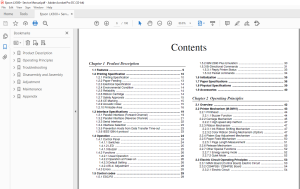
TABLE OF CONTENTS:
Epson LX300+ Service Manual - PDF DOWNLOAD
Product Description 8
11 Features 9
12 Printing Specification 10
121 Printing Specification 10
122 Paper Feeding 13
123 Electrical Specification 14
124 Environmental Condition 14
125 Reliability 14
126 Ribbon Cartridge 14
127 Safety Approvals 15
128 CE Marking 15
129 Acoustic noise: 15
1210 Printable Area 16
13 Interface Specifications 19
131 Parallel Interface (Forward Channel) 19
132 Parallel Interface (Reverse Channel) 21
133 Serial Interface 22
134 Interface Selection 23
135 Prevention Hosts from Data Transfer Time-out 23
136 IEEE12844 protocol 23
14 Operation 24
141 Control Panel 24
1411 Switches 24
1412 LED 25
1413 Buzzer 25
142 Functions 26
1421 Usual Operation 26
1422 Operation at Power-on 26
1423 Default Setting 26
1424 Bi-d Adjustment 28
143 Errors 28
15 Control codes 29
151 ESC/P2 29
152 IBM 2390 Plus Emulation 30
153 Bi-Directional Commands 31
1531 Reply Printer Status 33
1532 Packet commands 34
16 Initialization 35
17 Paper Specifications 36
18 Physical Specifications 39
19 Accessories 40
Operating Principles 41
21 Overview 42
22 Printer Mechanism (M-3M10) 43
221 Printhead 44
2211 Buzzer Function 44
222 Carriage Mechanism 45
2221 High speed skip method 47
223 Ribbon Mechanism 47
2231 Ink Ribbon Shifting Mechanism 47
2232 Color Ribbon Driving Mechanism (Option) 47
224 Platen Gap Adjustment Mechanism 49
225 Paper Feed Mechanism 50
2251 Page Length Measurement 51
226 Release Mechanism 52
227 Other Special Functions 52
2271 Energy saving mode 52
2272 Quiet Mode 52
23 Electric Circuit Operating Principles 53
231 MAIN Board (Control Board) Electric Circuit 53
232 C294PSB / C294PSE Board 54
2321 Electric Circuit 54
Troubleshooting 55
31 Overview 56
32 Troubleshooting 57
321 Initialization Check 57
322 Check Performance By Self-Check Function 57
3221 Indicator LED 57
323 Identify Problems From Symptoms 58
324 Unit and Parts Check 61
3241 Printhead Check 61
3242 Motor Check 62
3243 Sensor Check 62
3244 Printhead Driver Check 63
Disassembly and Assembly 64
41 Overview 65
411 Precautions 65
412 Tools 65
413 Service Checks After Repair 66
42 Disassembly and Assembly 67
421 Printhead Removal 68
422 Upper Housing Removal 69
423 Printer Mechanism Removal 70
424 Board Assembly and Panel Removal 71
425 C294MAIN Board Assembly Removal 71
426 P/S Board Assembly Removal 72
427 Printer Mechanism Disassembly 73
4271 CR Motor Assembly Removal 73
4272 Platen Removal 74
4273 Carriage Unit Removal 75
4274 Ribbon Feed Mechanism Removal 76
4275 RPE Sensor Removal 77
4276 BPE Sensor Removal 77
4277 HP Sensor Removal 77
4278 PG Sensor Removal 78
4279 Release Lever Position Sensor Removal 78
42710 PF Motor Assembly Removal 79
42711 Paper Feed Mechanism Disassembly 79
42712 Paper Guide Removal 81
Adjustment 82
51 Overview 83
511 Platen Gap Adjustment 83
512 Bi-D Adjustment 84
Maintenance 88
61 Maintenance 89
611 Cleaning 89
612 Lubrication 89
Appendix 93
71 Connector Summary 94
72 Parts List 97
73 Exploded Diagrams100
74 Component Layout102
75 Circuit Schematics103
S.M 28/2/2025
More products