$35
Epson Stylus Color 440 - 640- 740 Service Manual - PDF DOWNLOAD
Epson Stylus Color 440 - 640- 740 Service Manual - PDF DOWNLOAD
FILE DETAILS:
Epson Stylus Color 440 - 640- 740 Service Manual - PDF DOWNLOAD
Language :English
Pages :212
Downloadable : Yes
File Type : PDF
IMAGES PREVIEW OF THE MANUAL:
DESCRIPTION:
Epson Stylus Color 440 - 640- 740 Service Manual - PDF DOWNLOAD
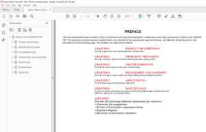
PREFACE
This manual describes basic functions, theory of electrical and mechanical operations, maintenance and repair procedures of Stylus Color 440/640/
740. The instructions and procedures included herein are intended for the experienced repair technicians, and attention should be given to the
precautions on the preceding page. The chapters are organized as follows:
CHAPTER 1. PRODUCT DESCRIPTIONS
Provides a general overview and specifications of the product.
CHAPTER 2. OPERATING PRINCIPLES
Describes the theory of electrical and mechanical operations of the product.
CHAPTER 3. TROUBLESHOOTING
Provides the step-by-step procedures for troubleshooting.
CHAPTER 4. DISASSEMBLY AND ASSEMBLY
Describes the step-by-step procedures for disassembling and assembling the product.
CHAPTER 5. ADJUSTMENTS
Provides Epson-approved methods for adjustment.
CHAPTER 6. MAINTENANCE
Provides preventive maintenance procedures and the lists of Epson-approved lubricants and
adhesives required for servicing the product.
APPENDIX
Provides the following additional information for reference:
• Connector pin assignments
• Electric circuit boards components layout
• Exploded diagram
• Electrical circuit boards schematics
TABLE OF CONTENTS:
Epson Stylus Color 440 - 640- 740 Service Manual - PDF DOWNLOAD
Stylus Color 440/640/740 1
Product description 8
11 Features 9
12 Specifications 11
121 Printing Specification 11
122 Paper Specification 15
1221 Cut Sheet 15
1222 Transparency, Glossy Paper 15
1223 Envelope 15
1224 Index Card 16
123 Printing Area 17
1231 Adjust Lever Setting 19
124 Ink Cartridge Specifications 20
125 Environmental Condition 22
126 Electric Specification 23
127 Reliability 23
128 Safety Approvals 23
129 Acoustic Noise 24
1210 CE Marking 24
1211 Input Data Buffer 24
13 Interface 25
131 Parallel Interface (Forward Channel) 25
132 Parallel Interface (Reverse Channel) 27
1321 Prevention Hosts from Data Transfer time-out 30
1322 Auto Interface Selection (for Stylus Color 640, 740) 30
133 Serial Interface (for Stylus Color 640, 740) 31
1331 USB Interface (Only for Stylus Color 740) 31
14 Control Panel 32
141 Indicators (LEDs) 32
142 Panel Functions 33
143 Printer Condition and Panel Status 34
15 Error Status 35
151 Ink Out 35
152 Paper Out 35
153 Paper Jam 35
154 No Ink-Cartridge 36
155 Maintenance Request 36
156 Fatal Errors 36
18 Main Components 38
181 Printer Mechanism 38
182 C206 Main-B Board (Stylus Color 440) 39
183 C256 Main Board (Stylus Color 640) 39
184 C257 Main Board (Stylus Color 740) 40
185 Power Supply Board C206 PSB/PSE (Stylus Color 440, 640) C257 PSB/PSE (Stylus Color 740) 40
186 C206 PNL Board (Stylus Color 440, 640) 41
187 C209 PNL Board (Stylus Color 740) 41
16 Printer Initialization 37
17 Initialization Settings 37
Operating principles 42
21 Overview 43
211 Printer Mechanism 44
2111 Printing Mechanism 45
2112 Printing Process 46
2113 Carriage Mechanism 47
21131 Platen Gap Adjust Mechanism and Parallel adjustment Mechanism 49
2114 Paper Feed Mechanism and Pump Mechanism 49
2115 Ink System 52
2116 Pump, Carriage Lock, Head Cleaner Mechanism 53
21161 Cap Mechanism 55
22 Electrical Circuit Operating Principles 56
221 C206 PSB/PSE and C257 PSB/PSE Power Supply Board (for Stylus Color 440, 640, 740) 57
222 C206 Main-B, C255 Main (for Stylus Color 440) 60
223 C256 Main (for Stylus Color 640) 62
224 C257 Main, (for Stylus Color 740) 64
2241 Reset Circuits 66
2242 Sensor Circuits 68
2243 EEPROM Control Circuits 70
2244 Timer Circuit 71
2245 DRAM Control 72
2246 Print Head Control Circuit 72
2247 PF (Pump) Motor Drive Circuit 76
2248 CR Motor Drive Circuit 78
Troubleshooting 81
31 Troubleshooting 82
32 Unit Level Troubleshooting 85
321 Printer does not operate at power on 85
322 Error is detected 86
323 Failure occurs during printing 86
324 Printer does not feed paper correctly 87
325 Control panel operation is abnormal 87
33 Unit Repair of Power Supply Board 88
34 Unit Repair of the Main Board 91
35 Repair of the Printer Mechanism 96
Disassembly and assembly 99
41 Overview100
411 Precautions for Disassembling the Printer100
412 Tools101
413 Specification for Screws102
414 Service Checks After Repair103
42 Disassembly Procedures104
421 Removing the Housing105
422 Removing the Board Assembly106
423 Removing the Operation Panel108
424 Disassembling the Printer Mechanism109
4241 Removing the Print Head Unit109
4242 Removing the Absorber Tray Assembly ;A112
4243 Removing the Pump Assembly and Cap Assembly113
4244 Removing the CR Motor Assembly116
4245 Removing the PF Motor Assembly117
4246 Removing the ASF Assembly119
42461 Removing the Paper Feed Roller Assembly120
42462 Removing the Right and Left LD Roller Assembly122
4247 Removing the Carriage Assembly123
4248 Removing the PF Roller Assembly125
4249 Removing the PE Paper Detector Assembly127
42410 Removing the HP Detector128
Adjustment129
51 Overview130
511 Required Adjustments130
512 Adjustment Tools Required131
52 Adjustment132
521 Parallelism Adjustment132
522 Adjustment by Adjustment Program134
5221 About Adjustment Program134
5222 Entering the Main menu136
52221 Registering the printer model name138
52222 Setting the CG (Destination information) (For Stylus Color 740 only)139
5223 Initial Ink Charge Operation140
5224 Head Cleaning Operation141
5225 Protection Counter Indicate/Reset142
5226 Market/Destination Check (only for Stylus Color 740)144
5227 Head Voltage ID Input146
5228 Head Angular Adjustment148
5229 Bi-D Adjustment151
Maintenance153
Maintenance153
61 Overview154
611 Cleaning154
612 Service Maintenance154
613 Lubrication155
Appendix160
A1 Connector Summary161
A11 Connector Summary (Stylus Color 440/640)162
A111 Connector Pin Assignment (Stylus Color 440 and Stylus Color 640)163
A12 Connector Summary for Stylus Color 740166
A121 Connector Pin Assignment (Stylus Color 740)167
A2 EEPROM Address Map169
A21 EEPROM ADDRESS Map (Stylus Color 440/ 640)169
A22 EEPROM Address Map (Stylus Color 740)174
A3 Circuit Board Component Layouts178
A4 Exploded Diagrams188
A 5 Part List198
A 51 Part List for Stylus Color 440/ 640198
A 52 Part List for Stylus Color 740200
A6 Circuit Diagrams202
S.M 28/2/2025
More products