$45
EPSON STYLUS COLOR 680/777/777i Service Manual - PDF DOWNLOAD
EPSON STYLUS COLOR 680/777/777i Service Manual - PDF DOWNLOAD
FILE DETAILS:
EPSON STYLUS COLOR 680/777/777i Service Manual - PDF DOWNLOAD
Language :English
Pages :145
Downloadable : Yes
File Type : PDF
IMAGES PREVIEW OF THE MANUAL:
DESCRIPTION:
EPSON STYLUS COLOR 680/777/777i Service Manual - PDF DOWNLOAD
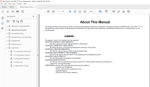
About This Manual
This manual describes basic functions, theory of electrical and mechanical operations, maintenance and repair procedures of EPSON Stylus Color 680/777/777i.
The instructions and procedures included herein are intended for the experienced repair technicians, and attention should be given to the precautions on the
preceding page.
Contents
This manual consists of six chapters and one Appendix.
CHAPTER 1.PRODUCT DESCRIPTIONS
Provides a general overview and specifications of the product.
CHAPTER 2.OPERATING PRINCIPLES
Describes the theory of electrical and mechanical operations of the product.
CHAPTER 3.TROUBLESHOOTING
Provides the step-by-step procedures for the troubleshooting.
CHAPTER 4.DISASSEMBLY AND ASSEMBLY
Describes the step-by-step procedures for dissaembling and assembling the product.
CHAPTER 5.ADJUSTMENTS
Provides Epson-approved methods for adjustment.
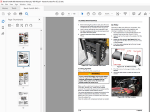
CHAPTER 6.MAINTENANCE
Provides preventive maintenance procedures and the lists of Epson-approved lubricants and adhesives
required for servicing the product.
APPENDIXProvides the following additional information for reference:
• Connector pin assignments
• Electric circuit boards components layout
• Exploded diagram
• Electrical circuit boards schematics
TABLE OF CONTENTS:
EPSON STYLUS COLOR 680/777/777i Service Manual - PDF DOWNLOAD
PRODUCT DESCRIPTION 9
11 FEATURES 10
12 SPECIFICATIONS 11
121 Physical Specification 11
122 Printing Specification 11
123 Paper Feeding 12
124 Input Data Buffer 12
125 Electric Specification 12
126 Environmental Condition 13
127 Reliability 13
128 Safety Approvals 13
129 Acoustic Noise 13
1210 CE Marking 13
13 INTERFACE 14
131 Parallel Interface (Forward Channel) 14
132 Parallel Interface (Reserve Channel) 17
133 USB Interface 18
134 Prevention of Data Transfer Time-out 19
135 Interface Selection 19
136 IEEE12844 Protocol 19
14 OPERATOR CONTROLS 20
141 Operating Switch 20
142 Control Panel 20
1421 Switches 20
1422 Indicators 20
143 Panel Functions 21
144 Printer Condition and Panel Status 22
145 Printer Initialization 22
146 Errors 23
15 PAPER 24
151 Paper Handling 24
152 Paper Specification 24
1521 Cut Sheet 24
1522 Transparency, Glossy Paper 24
1523 Envelope 24
1524 Index Card 25
153 Printing Area 26
1531 Cut Sheet 26
1532 Envelopes 27
16 INK CARTRIDGE 28
161 Black Ink Cartridge 28
162 Color Ink Cartridge 28
Operating Principles 29
21 Overview 30
211 Printer Mechanism 30
212 Printhead 31
2121 Printing Process 32
2122 Printing Method 32
213 Carriage Mechanism 33
214 Paper Feeding Mechanism 34
215 Paper Loading Mechanism (ASF Unit) 35
216 Ink System Mechanism 38
2161 Pump Unit & Wiper mechanism 38
2162 Capping Mechanism 39
22 Electrical Circuit Operating Principles 40
221 C383 PSB/PSE board 40
222 C383 MAIN Board 43
2221 Main elements 44
2222 Printhead Driver Circuit 45
2223 PF Motor (PF/ PUMP/ ASF Motor) Driver Circuit 46
2224 CR Motor Driver Circuit 46
2225 Reset Circuit 47
2226 EEPROM Control Circuit 47
2227 Sensor Circuit 48
Troubleshooting 49
31 Overview 50
32 Troubleshooting with LED Error Indications 51
Disassembly and Assembly 61
41 Overview 62
411 Precautions 62
412 Tools 63
413 Work Completion Check 64
42 Disassembly 65
421 Housing removal 66
422 Operation Panel removal 67
423 Printhead removal 68
424 CR motor removal 71
425 Waste drain ink pad unit removal 73
426 Circuit board removal 75
427 LD Roller removal 79
428 HP/PE Sensor removal 83
429 Ink system unit removal (Cap & Pump unit ) 85
4210 Paper Eject Roller removal 87
4211 PF motor removal 89
4212 CR unit removal 91
4213 Paper feed roller removal 94
4214 Disassembling ASF frame unit 97
Adjustment100
51 Overview101
511 Required Adjustment101
512 Adjustment Program feature102
513 Adjustment Program Installation Procedure103
514 Adjustment Program Initial Setting menu103
515 Head ID Input103
516 Bi-D Adjustment105
517 USB ID input107
518 Head Cleaning Operation109
519 Initial Ink Charge Operation110
5110 Refurbishment for DOA111
5111 Protection Counter Check/Reset112
5112 Check pattern printing114
5113 EEPROM check function115
5114 CSIC Information116
Maintenance117
61 Overview118
611 Cleaning118
612 Service Maintenance119
613 Lubrication119
Appendix123
71 Connector Summary124
711 Major Component Unit124
712 EEPROM Address Map127
72 Component Layout131
73 Exploded Diagram133
74 Parts List138
75 Electrical Circuits141
S.M 28/2/2025
More products