$45
Epson Stylus Color 860/1160 Service Manual - PDF DOWNLOAD
Epson Stylus Color 860/1160 Service Manual - PDF DOWNLOAD
FILE DETAILS:
Epson Stylus Color 860/1160 Service Manual - PDF DOWNLOAD
Language :English
Pages :189
Downloadable : Yes
File Type : PDF
IMAGES PREVIEW OF THE MANUAL:
DESCRIPTION:
Epson Stylus Color 860/1160 Service Manual - PDF DOWNLOAD
PREFACE
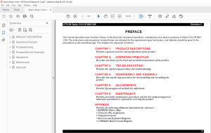
This manual describes basic functions, theory of electrical and mechanical operations, maintenance and repair procedures of Stylus COLOR 860/
1160. The instructions and procedures included herein are intended for the experienced repair technicians, and attention should be given to the
precautions on the preceding page. The chapters are organized as follows:
CHAPTER 1. PRODUCT DESCRIPTIONS
Provides a general overview and specifications of the product.
CHAPTER 2. OPERATING PRINCIPLES
Describes the theory of electrical and mechanical operations of the product.
CHAPTER 3. TROUBLESHOOTING
Provides the step-by-step procedures for troubleshooting.
CHAPTER 4. DISASSEMBLY AND ASSEMBLY
Describes the step-by-step procedures for disassembling and assembling the
product.
CHAPTER 5. ADJUSTMENTS
Provides Epson-approved methods for adjustment.
CHAPTER 6. MAINTENANCE
Provides preventive maintenance procedures and the lists of Epson-approved
lubricants and adhesives required for servicing the product.
APPENDIX
Provides the following additional information for reference:
• EEPROM Address Map
• Connector Pin Assignments
• Component Layout
• Parts List and Exploded Diagrams
• C298MAIN Board Circuit Diagram
TABLE OF CONTENTS:
Epson Stylus Color 860/1160 Service Manual - PDF DOWNLOAD
PRODUCT DESCRIPTION 8
11 FEATURES 9
12 SPECIFICATIONS 10
121 Physical Specification 10
122 Printing Specification 10
123 Paper Feeding 11
124 Input Data Buffer 11
125 Electric Specification 11
126 Environmental Condition 12
127 Reliability 12
128 Safety Approvals 12
129 Acoustic Noise 12
1210 CE Marking 12
13 INTERFACE 13
131 Parallel Interface (Forward Channel) 13
132 Parallel Interface (Reserve Channel) 16
133 USB Interface 17
134 Prevention of Data Transfer Time-out 18
135 Interface Selection 18
136 IEEE12844 Protocol 18
14 OPERATOR CONTROLS 19
141 Operating Switch 19
142 Control Panel 19
1421 Switches 19
1422 Indicators 19
143 Panel Functions 20
144 Printer Condition and Panel Status 21
145 Printer Initialization 21
146 Errors 22
15 PAPER 23
151 Paper Handling 23
152 Paper Specification 23
1521 Cut Sheet 23
1522 Transparency, Glossy Paper 23
1523 Envelope 23
1524 Index Card 24
153 Printing Area 25
1531 Cut Sheet 25
1532 Envelopes 26
16 INK CARTRIDGE 27
161 Black Ink Cartridge 27
162 Color Ink Cartridge 27
Operating Principles 28
21 Overview 29
211 Printer Mechanism 29
2111 Printing Mechanism 30
2112 Printing Process 31
2113 Carriage Mechanism 32
2114 Platen Gap (PG) Adjust Mechanism 33
2115 Paper Feeding Mechanism 33
2116 CR Lock Mechanism 35
2117 Paper Loading Mechanism 36
2118 Pump Mechanism 38
2119 Capping Mechanism 39
22 Electrical Circuit Operating Principles 40
221 C298PSB/PSE Board 41
222 C298MAIN Board 43
2221 Printhead Driver Circuit 45
2222 Reset Circuit 46
2223 CR Motor Driver Circuit 47
2224 PF Motor Driver Circuit 49
2225 ASF/Pump Motor Driver Circuit 50
2226 EEPROM Control Circuit 50
2227 Sensor Circuit 51
Troubleshooting 53
31 Overview 54
311 Troubleshooting with LED Error Indications 55
3111 Remedies for Paper Out Error 57
3112 Remedies for the Paper Jam Error 59
3113 Remedies for No I/C and Ink Out Errors 60
3114 Remedies for the Maintenance Error 62
3115 Remedies for Fatal Error 63
312 Isolating the Faulty Part on the Power Supply Board 66
313 Isolating the Faulty Part according to the Phenomenon 68
Disassembly and Assembly 74
41 Overview 75
411 Precautions for Disassembling the Printer 75
412 Tools 76
413 Specification for Screws 77
414 Service Checks After Repair 78
42 Disassembly Procedures 79
421 Removing the Upper Housing 80
422 Removing the Circuit Board Assembly 81
423 Removing the Operation Panel 83
424 Disassembling the Printer Mechanism 84
4241 Removing the Printhead Unit 85
4242 Removing the Waste Ink Absorber Tray Assembly 87
4243 Removing the Ink System Assembly 89
4244 Removing the CR Motor Assembly 92
4245 Removing the DE Assembly (include the ASF/Pump motor) 93
4246 Removing the ASF Assembly 97
42461 Removing the Paper Feed Roller Assembly 99
42462 Removing the Right and Left LD Roller Assembly104
4247 Removing the CR Assembly105
42471 Disassembling the CR Assembly108
4248 Removing the PF Roller Assembly and Paper Eject Roller Assembly110
4249 Remove the PF Motor Assembly114
42410 Removing the PE Detector Assembly115
Adjustment116
51 Overview117
511 Required Adjustments117
512 Adjustment Tools Required118
52 Adjustment119
521 Parallelism Adjustment119
522 Backlash value Adjustment for PF motor122
523 Adjustment by Adjustment Program125
5231 About Adjustment Program125
5232 How to set up the program125
5233 Choose the Model126
5234 Market Destination Check127
5235 Head Voltage ID Input128
5236 Head Angular Adjustment131
5237 Bi-D Adjustment134
5238 USB ID input137
5239 Initial Ink Charge Operation141
52310 Head Cleaning Operation142
52311 Protection Counter Check/Reset143
52312 Recovery for the clogged nozzle145
52313 Print A4 pattern146
53 PF Loop scale unit assembling procedure147
531 Assembling the PF Loop scale unit147
532 Sticking the PF Loop scale unit to Gear 76149
Maintenance150
61 Overview151
611 Cleaning151
612 Service Maintenance151
613 Lubrication152
Appendix160
71 Connector Summary161
711 Connector Pin Assignment161
712 EEPROM ADDRESS MAP164
72 Circuit Board Component Layout169
73 Exploded Diagrams and Parts List for Stylus COLOR 860172
74 Exploded Diagrams and Parts List for Stylus COLOR 1160180
75 Circuit Diagram189
S.M 26/2/2025
More products